Table of Contents
Advertisement
SZX9/12
SZX-EPA
SZX-AS
SZX-R
SZX-2RE
SZX-STAD1
SZX-STAD2
INSTRUCTIONS
SZH-STAD1
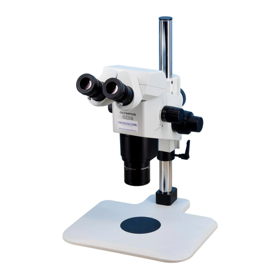
SZX
RESEARCH STEREOMICROSCOPE
SYSTEM
This instruction manual is for the Olympus SZX Research Stereomicroscope System. To ensure the
safety, obtain optimum performance and to familiarize yourself fully with the use of this microscope,
we recommend that you study this manual thoroughly before operating the microscope. Retain this
instruction manual in an easily accessible place near the work desk for future reference.
A X 7 1 6 8
Advertisement
Table of Contents

Related Manuals for Olympus SZX9


Summary of Contents for Olympus SZX9
- Page 1 RESEARCH STEREOMICROSCOPE SYSTEM This instruction manual is for the Olympus SZX Research Stereomicroscope System. To ensure the safety, obtain optimum performance and to familiarize yourself fully with the use of this microscope, we recommend that you study this manual thoroughly before operating the microscope. Retain this instruction manual in an easily accessible place near the work desk for future reference.
-
Page 2: Safety Precautions
IMPORTANT SAFETY PRECAUTIONS 1. To prevent the microscope body from turning over, its pivot angle must be limited to 30° as shown in Fig. 1. 2. Sufficient care is required during observation with a magnification objec- tive, because the objective´s long working distance can displace the microscope body to a higher position. -
Page 3: Maintenance And Storage
4. Only one intermediate attachment can be used. Using two attachments may obscure a part of the image. However, the vertical illuminator (SZX- ILLC) is not considered to be an attachment. }When more than one intermediate attachment is to be combined, they should be stacked according to the following order, from the bottom to the top: SZX-ILLC, SZX-AS, SZX-RFA (SZX-RFL), SZX-SDO, SZX-APT, SZX- BS, SZX-DA, SZX-FAD, then SZX-EPA . -
Page 4: Table Of Contents
CONTENTS NOMENCLATURE ASSEMBLY 2-1 Assembly Diagram ..................................2 2-2 Detailed Assembly Procedure ............................3 CONTROLS SUMMARY OF OBSERVATION PROCEDURE 4-1 Preparation ....................................... 7 4-2 Observation Procedure ................................7 USING THE CONTROLS 5-1 Base ............................................ 8 5-2 Microscope Body and Focusing Assembly....................8 5-3 Observation Tube .................................. -
Page 5: Nomenclature
NOMENCLATURE Eyepiece · WHS10X-H · CROSS WHS10X Observation tube · WHS15X-H · Binocular observation · CROSS WHS15X tube: SZX-BI30/BI45 · WHS20X-H · Trinocular observation · CROSS WHS20X tube: SZX-TR30 · WHS30X-H · Tilting binocular tube: SZX-TBI Focusing assembly · Coarse/fine focus adjustment knobs: SZX-FOF ·... -
Page 6: Assembly
ASSEMBLY 2-1 Assembly Diagram The diagram below shows how to assemble the various modules. The numbers indicate the order of assembly. # When assembling the microscope, make sure that all parts are free of dust and dirt, and avoid scratching any parts or touching glass surfaces. -
Page 7: Detailed Assembly Procedure
2-2 Detailed Assembly Procedure Installing the Pillar (Fig. 3) 1. Using the Allen wrench provided with the base, loosen the 2 clamping ² screws @ on the pillar support sleeve completely. 2. Hold the pillar ² with the white rubber cap at the top, and insert it into the pillar support sleeve until it reaches the bottom. - Page 8 Mounting the Microscope Body (Fig. 6) 1. Remove the cap @ on the focusing assembly by inserting a thin object into the notch. 2. Using the provided Allen screwdriver, loosen the dovetail mount clamp- ing screw inside the cap on the focusing assembly by rotating it by 2 or ³...
- Page 9 Mounting the Eyepiece (Fig. 9) 1. Remove the eyepiece dust caps @ and loosen the eyepiece clamping screws ² completely. 2. Gently insert the cross-lined eyepiece (CROSS WHS10X) ³ (if this is not provided, use the WHS10X-H) into the right eyepiece sleeve until it stops. ³...
-
Page 10: Controls
CONTROLS Light path selector knob (SZX-TR30 only) Zooming knob SZX-ZB12: 0.7X to 9X SZX-ZB9: 0.63X to 5.7X Coarse focus adjustment knob tension adjustment ring Diopter adjustment ring ± 5m (per meter) Fine focus adjustment knob (SZX-FOF only) Eyepiece clamping knob Stroke: 80 mm Stroke per turn: 1.5 mm Aperture iris diaphragm ring... -
Page 11: Summary Of Observation Procedure
SUMMARY OF OBSERVATION PROCEDURE 4-1 Preparation 1. Check and tighten the connection of each component, especially the observation tube............(Page 4) 2. Adjust the position of the microscope body......................................(Page 5) 3. Adjust the tension of the coarse focus adjustment knob..............................(Page 8) 4. -
Page 12: Using The Controls
USING THE CONTROLS 5-1 Base Using the Stage Plate When reflected light is used, the stage plate is usually placed with the white side facing up. In case the specimen is white or other bright colors, place the stage plate with the black side up to improve contrast. # When transmitted light is used, use the transparent glass stage plate (SP-C). - Page 13 Engagement and Disengagement of the (Fig. 14) Zooming Knob Click Stop Function }When the click stop knob is set to ON, the click stop function is engaged for each magnification indicated with the zooming knob. When the knob is set to OFF, the zoom magnification can be varied continuously and finely near the click groove.
- Page 14 Magnification Indicator Ring (Fig. 16) }Every objective other than the 1X objective is provided with an observa- tion magnification* indicator ring. ² * This refers to the total magnification when the 10X eyepiece is used. }When the revolving nosepiece (SZX-2RE) is used, the total observation magnifications when two objectives are switched can be read directly by mounting these rings on the left and right zooming knobs.
-
Page 15: Observation Tube
5-3 Observation Tube Interpupillary Distance Adjustment (Fig. 20) # Be sure to hold the binocular assembly @ with both hands to make this adjustment. While looking through the eyepieces, hold the left and right of the bin- ocular assembly @ and adjust the eyepieces by opening or closing them for binocular vision until the left and right fields of view coincide completely. - Page 16 Using the Eye Shades (Fig. 22) When Wearing Eyeglasses Use with eye shades in their normal folded-down position. This will pre- vent eyeglasses from being scratched by the eyepiece. When Not Wearing Eyeglasses Extend the folded eyeshades in the direction of the arrow. This makes observation easier by preventing the inverse incidence of light from be- tween the eyepiece and your eyes.
- Page 17 Light Path Selection (SZX-TR30) (Fig. 24) Slide the light path selector knob @ to select the desired light path. Light Path Indication Intensity Ratio Selector Knob Pushed in 100% for binocular eyepieces. Pulled out 20% for binocular eyepieces. 80% for photomicrography and TV observation.
-
Page 18: Tv Observation And Photomicrography
5-4 TV Observation and Photomicrography }When TV observation or photomicrography is required, use the SZX-TR30 trinocular tube. A TV camera and/or digital camera unit can be mounted on the SZX-TR30 trinocular tube by means of the TV adapter and/or camera mount adapter*. * The camera mount adapter is not necessary if a TV adapter equipped with a camera mount is used. -
Page 19: Specifications
SPECIFICATIONS Item Specification SZX-ZB12 SZX-ZB9 1. Zoom microscope body · SZX-ZB12 Left/right zoom magnification system. · SZX-ZB9 Zoom drive system: Horizontal knob. Click stop ON-OFF switchable per zoom magnification. Zoom ratio: 12.8 (0.7X to 9X) Zoom ratio: 9 (0.63X to 5.7X) Magnification indications*: Magnification indications*: 7, 10, 12.5, 16, 20, 25, 32, 40, 50, 63, 90... - Page 20 Item Specification 6. Objectives SZX-ZB12 SZX-ZB9 WD: Working distance Model Model PF: Parfocal lens DFPLFL0.3X 130 mm* DFPL0.5X-4 171 mm* DFPLFL0.45X 198 mm* DFPL0.75X-4 116 mm DFPLFL0.5XPF 70 mm DFPLAPO1X-4 81 mm DFPLAPO1XPF 74 mm SZX-ACH1X 90 mm DFPLAPO1.2XPF2 60 mm SZX-ACH1.25X 68 mm * Auxiliary pillar is required when...
-
Page 21: Optical Characteristics
OPTICAL CHARACTERISTICS ■ SZX-ZB12 Eyepiece WHS10X-H WHS15X-H WHS20X-H WHS30X-H Objective Field of view Field of view Field of view Field of view Total Mag. Total Mag. Total Mag. Total Mag. (mm) (mm) (mm) (mm) DFPLFL0.3X 2.1X - 27X 104.8 - 8.1 3.15X - 40.5X 76.2 - 5.9 4.2X - 54X 59.5 - 4.6... -
Page 22: Troubleshooting Guide
Under certain conditions, performance of this unit may be adversely affected by factors other than defects. If a problem occurs, please review the following list and take remedial action as needed. If you cannot solve the problem after checking the entire list, please contact your local Olympus representative for assistance. Problem... -
Page 23: Operation Of Other Attachments
OPERATION OF OTHER ATTACHMENTS 9-1 Eyepoint Adjuster SZX-EPA External View Observation tube clamping screw Assembly (Fig. 27) 1. Using the Allen screwdriver provided with the SZX microscope body, remove the observation tube @. 2. Mount the eyepoint adjuster ² to the place where the observation tube ²... -
Page 24: As Unit Szx-As (For Use With The Szx-Zb9)
9-2 AS Unit SZX-AS (for use with the SZX-ZB9) External View Aperture iris diaphragm adjustment Observation tube clamping screw lever Assembly }The AS unit can be mounted in the same manner as the SZX-EPA eyepoint adjuster, which is described in section 9-1. Using the Aperture Iris Diaphragm }By adjusting the aperture iris diaphragm, it is possible to improve the contrast of the observed image and increase the depth of focus. -
Page 25: Drop Prevention Collar Szx-R And Auxiliary Pillar Szh-P400/Szh-P600
9-3 Drop Prevention Collar SZX-R and Auxiliary Pillar SZH-P400/SZH-P600 }The auxiliary pillar is to be used when observing a large specimen or when it is required to move the microscope body height using a low-magnification objective. }The drop prevention collar prevents the zoom microscope body from dropping when installed at a high position using the auxiliary pillar and the clamping knob on the focusing assembly is loosened carelessly. -
Page 26: Revolving Nosepiece Szx-2Re
9-4 Revolving Nosepiece SZX-2RE External View Hand guard Allen wrench (for M3 screws) M3 –– 4 mm long (x 2) Objective mounts Clamping Nosepiece mount screws M3 –– 6 mm long (x 3) Assembly (Figs. 29 - 32) 1. Attach the hand guard ² to the revoling noseplece @ by tightening the ³... - Page 27 5. Place the nosepiece mount … (with its objective mounts † facing … † ‡ upward) where the objective has been by aligning the screw holes. Š Using the Allen wrench (for M3 screws), clamp the revolver mount with the provided 3 clamping screws (M3 –– 6 mm long). (Fig. 31) # As the screw holes may be hidden behind the objective mounts †, clamp the nosepiece mount while rotating it.
-
Page 28: Bx Stage Adapter Type 1 Szx-Stad1
9-5 BX Stage Adapter Type 1 SZX-STAD1 Introduction This adapter is for installation of a U-SRG or U-SRP rotary stage on the SZX standard base or a SZX series illumination base. When the U-SRP rotary stage is used together with the U-FMP mechanical stage, X-Y directional movement be- comes possible, which is convenient for framing during photomicrography. - Page 29 Assembly Mechanical stage U-FMP Rotary stage Rotary stage U-SRP U-SRG Clamping screws Allen screwdriver (provided with the microscope body) BX stage adapter type 1 SZX-STAD1 Clamping screw Attaching hole Attaching threaded hole Base Mounting the Polarizer (SZX-PO) When simplified transmitted polarized light observation is required, install the polarizer on the SZX-STAD1 BX stage adapter type 1.
-
Page 30: Bx Stage Adapter Type 2 Szx-Stad2
9-6 BX Stage Adapter Type 2 SZX-STAD2 Introduction This adapter is for installing the U-SIC large stage* on the SZX-STL large stand**. When this stage adapter is used, the SZH-P400 auxiliary pillar should be used to cover the height of the stage adapter. In addition, when an objective with a long working distance (DFPLFL0.3X, DFPLFL0.45X or DFPL0.5X) is used, the SZH-P600 auxiliary pillar should be used (always together with the drop prevention collar). -
Page 31: Stage Adapter Type 1 Szh-Stad1
Simplified Transmitted Light Observation (Fig. 34) 1. Illuminate the specimen with an external light source (LSD illuminator, Microscope light guide illuminator, etc.). body Light the external light source as shown in the figure on the left and Objective Frosted filter irradiate the mirror assembly. - Page 32 MEMO...
- Page 33 MEMO...
- Page 34 2-43-2, Hatagaya, Shibuya-ku, Tokyo, Japan Postfach 10 49 08, 20034, Hamburg, Germany 2 Corporate Center Drive, Melville, NY 11747-3157, U.S.A. One Corporate Drive, Orangeburg, NY 10962, U.S.A. 491B River Valley Road, #12-01/04 Valley Point Office Tower, Singapore 248373 2-8 Honduras Street, London EC1Y OTX, United Kingdom. 31 Gilby Road, Mt.