
Related Manuals for Canon GP605


Summary of Contents for Canon GP605
- Page 1 SERVICE MANUAL REVISION 0 FY8-13FD-000 JAN. 1999 COPYRIGHT © 1999 CANON INC. CANON GP605/GP605V REV.0 JAN. 1999 PRINTED IN JAPAN (IMPRIME AU JAPON)
- Page 2 Prepared by OFFICE IMAGING PRODUCTS TECHNICAL SUPPORT DEPARTMENT 3 OFFICE IMAGING PRODUCTS TECHNICAL SUPPORT DIVISION CANON INC. 5-1, Hakusan 7-chome, Toride, Ibaraki, 302-8501 Japan COPYRIGHT © 1999 CANON INC. CANON GP605/GP605V REV.0 JAN. 1999 PRINTED IN JAPAN (IMPRIME AU JAPON)
- Page 5 INTRODUCTION This Service Manual contains basic data and figures on the GP605/605V needed to service the machine in the field. The copier is a multifunction machine designed to provide printer functions as an option. This Service Manual consists of the following chapters; refer to the Copier Basic Series as necessary for common technologies: CHAPTER 1 General Description introduces the copier’s features and specifications,...
- Page 6 Volume 3>Chapter 6>VI.A.2. "Cleaning the Charging Wire" The Copier Basic Series is a combination of descriptions on the existing technologies used in Canon copiers. It consists of the following seven volumes, and is intended to supplement the contents of Service Manuals:...
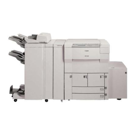
- Page 7 System Configuration The GP605/605V may be configured as follows: [1] Finisher-D1 [2] Printer Board [3] Copy tray [4] GP605/605V [5] Side Paper Deck-C1 Figure 1 COPYRIGHT © 1999 CANON INC. CANON GP605/605V REV.0 JAN. 1999 PRINTED IN JAPAN (IMPRIME AU JAPON)
- Page 8 MAIL BOX OPTIONS ON/OFF [1] Data lamp [2] Power switch [3] Main power switch [4] Heater switch Figure 2 Arrangement of the Switches COPYRIGHT © 1999 CANON INC. CANON GP605/605V REV.0 JAN . 1999 PRINTED IN JAPAN (IMPRIME AU JA PON)
-
Page 9: Table Of Contents
B. Basic Sequence of Operations B. Controlling the Scanner Motor ..........3-3 ..........3-6 C. Changing the Reproduction Ratio III. CONTROLLING THE SCANNING ..........3-4 LAMP .......... 3-8 COPYRIGHT © 1999 CANON INC. CANON GP605/605V REV.0 JAN. 1999 PRINTED IN JAPAN (IMPRIME AU JAPON) - Page 10 Boards ......4-28 Black Pixel Count ....4-20 Removing the Original IV. DISASSEMBLY/ASSEMBLY ..4-21 Detection PCB ....4-29 A. CCD PCB ......4-22 COPYRIGHT © 1999 CANON INC. CANON GP605/605V REV.0 JAN. 1999 PRINTED IN JAPAN (IMPRIME AU JAPON)
- Page 11 A. Controlling the Primary Charging control) ......6-28 Mechanism......6-16 Correcting the Output at the Outline ......6-16 Trailing Edge of Paper ..6-29 COPYRIGHT © 1999 CANON INC. CANON GP605/605V REV.0 JAN. 1999 PRINTED IN JAPAN (IMPRIME AU JAPON)
- Page 12 CHAPTER 7 PICK-UP/FEEDING SYSTEM OUTLINE........7-1 B. Arrangement of Rollers and A. Specifications and Construction Sensors ........7-2 ..........7-1 PICKUP ASSEMBLY ....7-3 viii COPYRIGHT © 1999 CANON INC. CANON GP605/605V REV.0 JAN. 1999 PRINTED IN JAPAN (IMPRIME AU JAPON)
- Page 13 E. No-Stacking Operation ..7-27 (right) ......7-55 Outline ......7-27 Removing the Pickup Outline of Operations ..7-28 Assembly of the Front Deck (left) ......... 7-56 COPYRIGHT © 1999 CANON INC. CANON GP605/605V REV.0 JAN. 1999 PRINTED IN JAPAN (IMPRIME AU JAPON)
- Page 14 (fixing system) ......8-4 Drive Mechanism ....8-8 FIXING DRIVE SYSTEM .... 8-5 D. Controlling the Fixing Inlet Guide A. Outline ........8-5 Drive Mechanism ....8-9 COPYRIGHT © 1999 CANON INC. CANON GP605/605V REV.0 JAN. 1999 PRINTED IN JAPAN (IMPRIME AU JAPON)
- Page 15 C. Rated Outputs of the DC Power Sequence of Operations ... 9-9 Supply PCB......9-16 V. POWER SUPPLY ..... 9-10 D. Protective Functions .... 9-17 E. Backup Battery ....9-18 COPYRIGHT © 1999 CANON INC. CANON GP605/605V REV.0 JAN. 1999 PRINTED IN JAPAN (IMPRIME AU JAPON)
- Page 16 Fan ........9-41 Relay PCB ......9-69 10. Removing the Pre-Transfer K. MFC PCB ......9-69 Charging Assembly Fan Routing the Belt ....9-71 ........9-42 COPYRIGHT © 1999 CANON INC. CANON GP605/605V REV.0 JAN. 1999 PRINTED IN JAPAN (IMPRIME AU JAPON)
- Page 17 Removing the Side Deck Removing the Right Cover Driver PCB ....10-44 ........10-24 Removing the Open Switch Removing the Upper Cover PCB....... 10-44 ........10-25 xiii COPYRIGHT © 1999 CANON INC. CANON GP605/605V REV.0 JAN. 1999 PRINTED IN JAPAN (IMPRIME AU JAPON)
- Page 18 II . STANDARDS AND ADJUSTMENTS Adjusting the Left/Right Non- ..........13-7 Image Width ....13-12 A. Adjusting Images ....13-7 Adjusting the Image Leading ........13-13 COPYRIGHT © 1999 CANON INC. CANON GP605/605V REV.0 JAN. 1999 PRINTED IN JAPAN (IMPRIME AU JAPON)
- Page 19 A. Making Initial Checks ..13-63 ........13-27 Checking the Site ..13-63 9-5. Position of the Multifeeder Checking the Originals Pickup Latching Solenoid ........13-63 COPYRIGHT © 1999 CANON INC. CANON GP605/605V REV.0 JAN. 1999 PRINTED IN JAPAN (IMPRIME AU JAPON)
- Page 20 41. E240 ......13-96 ........13-77 42. E241 ......13-96 18. The copy has a blurred image. 43. E243 ......13-96 ........13-78 44. E251 ......13-97 COPYRIGHT © 1999 CANON INC. CANON GP605/605V REV.0 JAN. 1999 PRINTED IN JAPAN (IMPRIME AU JAPON)
- Page 21 ........13-113 Emitting Diodes, and Check Pins 79. The Control Card Set by PCB ......13-146 message fails to turn on MFC PCB ....13-147 ........13-113 xvii COPYRIGHT © 1999 CANON INC. CANON GP605/605V REV.0 JAN. 1999 PRINTED IN JAPAN (IMPRIME AU JAPON)
- Page 22 D. SPECIAL TOOLS TABLE ..A-17 B. LIST OF SIGNALS/ E. SOLVENTS/OILS ..... A-19 ABBREVIATIONS ...... A-3 C. GENERAL CIRCUIT DIAGRAM ........... A-9 xviii COPYRIGHT © 1999 CANON INC. CANON GP605/605V REV.0 JAN. 1999 PRINTED IN JAPAN (IMPRIME AU JAPON)
-
Page 23: C. Extension Mode
D. Safety of Toner ....1-28 ..........1-16 VII. IMAGE FORMATION ....1-29 B. Control Panel ....... 1-17 A. Outline ........1-29 C. Extension Mode ....1-18 COPYRIGHT © 1999 CANON INC. CANON GP605/605V REV.0 JAN. 1999 PRINTED IN JAPAN (IMPRIME AU JAPON) -
Page 25: Chapter 1 General Description
• Saddle finisher* (middle bound booklet) *Accessory. Printer Functions The copier may be equipped with a printer board (accessory), servicing as a printer on a net- work. COPYRIGHT © 1999 CANON INC. CANON GP605/605V REV.0 JAN. 1999 PRINTED IN JAPAN (IMPRIME AU JAPON) -
Page 26: Specifications
760 W (main) + 400 W (sub) GP605V (100-V model): 850 W (main) + 360 W (sub) GP605 (120/230-V model): 910 W (main) + 390 W (sub) Table 1-202 COPYRIGHT © 1999 CANON INC. CANON GP605/605V REV.0 JAN. 1999 PRINTED IN JAPAN (IMPRIME AU JAPON) -
Page 27: Performance
279.4 × 431.8 mm (11"×17") max., STMT min. (vertical feeding) A3 max., A5 min. (vertical feeding) Double- sided Inch 279.4 × 431.8 mm (11"×17") max., STMT min. (vertical feeding) Table 1-203-1 COPYRIGHT © 1999 CANON INC. CANON GP605/605V REV.0 JAN. 1999 PRINTED IN JAPAN (IMPRIME AU JAPON) - Page 28 • Label Sheet (recommended by Canon) B4, A4, A4R, LTR, LTRR • Thick Paper (90 to 200 g/m A3, B4, A4, B5, A4R, B5R, LTR, LTRR Table 1-203-2 COPYRIGHT © 1999 CANON INC. CANON GP605/605V REV.0 JAN. 1999 PRINTED IN JAPAN (IMPRIME AU JAPON)
- Page 29 • Postcard (vertical feeding only) Japanese government postcards • Thick Paper (90 to 200 g/m A3, B4, A4, B5, A4R, B5R, LTR, LTRR Table 1-203-3 COPYRIGHT © 1999 CANON INC. CANON GP605/605V REV.0 JAN. 1999 PRINTED IN JAPAN (IMPRIME AU JAPON)
- Page 30 • Remote Diagnostic Device II • Copy Data Controller-A1 • Control Card V • Copy Tray Unit-D1 • Original Base D1 *When the ADF is used. Table 1-203-4 COPYRIGHT © 1999 CANON INC. CANON GP605/605V REV.0 JAN. 1999 PRINTED IN JAPAN (IMPRIME AU JAPON)
-
Page 31: Others
251Kg Copy paper Keep copy paper wrapped to protect against humidity. Avoid direct Consumables Toner sunshine, and keep at 40°C/85% or less. Table 1-204-1 COPYRIGHT © 1999 CANON INC. CANON GP605/605V REV.0 JAN. 1999 PRINTED IN JAPAN (IMPRIME AU JAPON) - Page 32 B4 A3 (115.4%) B5 A4 Note: A5R originals cannot be set in the ADF. *1-to-n values are in parentheses. Table 1-204-2 Copying Speed (copier alone) COPYRIGHT © 1999 CANON INC. CANON GP605/605V REV.0 JAN. 1999 PRINTED IN JAPAN (IMPRIME AU JAPON)
- Page 33 Note: A5R originals cannot be set in the ADF. *1-to-n values are in parentheses. Table 1-204-3 Copying Speed (copier alone) The specifications are subject to change for product improvement. COPYRIGHT © 1999 CANON INC. CANON GP605/605V REV.0 JAN. 1999 PRINTED IN JAPAN (IMPRIME AU JAPON)
-
Page 34: Side Paper Deck-C1
DC power from the copier. Same as the copier. Operating Conditions Temperature Humidity Atmospheric pressure Table 1-205 The specifications are subject to change for product improvement. 1-10 COPYRIGHT © 1999 CANON INC. CANON GP605/605V REV.0 JAN. 1999 PRINTED IN JAPAN (IMPRIME AU JAPON) -
Page 35: Names Of Parts
[15] Heater switch (cassette) [7] Lower right cover [16] Leakage breaker [8] Waste toner case/drum protective sheet holder Figure 1-301 External View 1 1-11 COPYRIGHT © 1999 CANON INC. CANON GP605/605V REV.0 JAN. 1999 PRINTED IN JAPAN (IMPRIME AU JAPON) - Page 36 [6] Grip, drum stop tool holder left: COPY (for normal copying) [7] Cover switch (door switch) assembly [12] LCD contrast adjuster Figure 1-302 External View 2 1-12 COPYRIGHT © 1999 CANON INC. CANON GP605/605V REV.0 JAN. 1999 PRINTED IN JAPAN (IMPRIME AU JAPON)
- Page 37 CHAPTER 1 GENERAL DESCRIPTION Blank Page 1-13 COPYRIGHT © 1999 CANON INC. CANON GP605/605V REV.0 JAN. 1999 PRINTED IN JAPAN (IMPRIME AU JAPON)
-
Page 38: Cross Section
[20] [21] [22] [23] [24] [38] [25] [37] [36] [35] [26] [27] [28] [29] [34] [30] [31] [32] [33] Figure 1-303 Cross Section 1-14 COPYRIGHT © 1999 CANON INC. CANON GP605/605V REV.0 JAN. 1999 PRINTED IN JAPAN (IMPRIME AU JAPON) - Page 39 [41] External delivery roller [20] Registration roller [42] No. 3 mirror [21] Transfer charging assembly [43] No. 2 mirror [22] Separation charging assembly Table 1-301 1-15 COPYRIGHT © 1999 CANON INC. CANON GP605/605V REV.0 JAN. 1999 PRINTED IN JAPAN (IMPRIME AU JAPON)
-
Page 40: Operating The Copier
MAIL BOX OPTIONS ON/OFF [1] Control panel power switch [2] Main power lamp [3] Main power switch Figure 1-401 Arrangement of the Switches 1-16 COPYRIGHT © 1999 CANON INC. CANON GP605/605V REV.0 JAN. 1999 PRINTED IN JAPAN (IMPRIME AU JAPON) -
Page 41: Control Panel
[8] Main power lamp* [17] Reset key [9] Stop key [18] Touch panel Figure 1-402 *Turns on when the main power switch is turned on. 1-17 COPYRIGHT © 1999 CANON INC. CANON GP605/605V REV.0 JAN. 1999 PRINTED IN JAPAN (IMPRIME AU JAPON) -
Page 42: Extension Mode
Use it to call back up to three copying modes stored in advance. BOOKLET Use it to make copies of a single- or double-sided original so that a booklet may be made. Table 1-401 Functions 1-18 COPYRIGHT © 1999 CANON INC. CANON GP605/605V REV.0 JAN. 1999 PRINTED IN JAPAN (IMPRIME AU JAPON) -
Page 43: User Mode
ON, density/image adjustment at Auto) Use it to return each copy settings item to factory settings. INITLALIZE CUSTOM COMMON SETTINGS *Factory setting. 1-19 COPYRIGHT © 1999 CANON INC. CANON GP605/605V REV.0 JAN. 1999 PRINTED IN JAPAN (IMPRIME AU JAPON) - Page 44 SERVER Use it to set the size of the image server. (300 to 1700 MB; CUSTOM HD MEMORY ASSIGNMENT 500MB*) SETTINGS *Factory settings. 1-20 COPYRIGHT © 1999 CANON INC. CANON GP605/605V REV.0 JAN. 1999 PRINTED IN JAPAN (IMPRIME AU JAPON)
-
Page 45: Routine Maintenance By The User
Wipe it with a moist cloth; then, dry wipe it. ADF feeding belt Wipe it with a cloth moistened with mild detergent solution; then, dry wipe it. Table 1-501 Parts 1-21 COPYRIGHT © 1999 CANON INC. CANON GP605/605V REV.0 JAN. 1999 PRINTED IN JAPAN (IMPRIME AU JAPON) -
Page 46: Safety
LASER DE CLASSE 1 APPARECCHIO LASER DI CLASSE 1 PRODUCTO LASER DE CLASE 1 APARELHO A LASER DE CLASSE 1 EN60825:1991 Figure 1-601 Laser Class Label 1-22 COPYRIGHT © 1999 CANON INC. CANON GP605/605V REV.0 JAN. 1999 PRINTED IN JAPAN (IMPRIME AU JAPON) -
Page 47: Cdrh Regulations
THIS PRODUCT CONFORMS WITH CQRH RADIATION PERFORMANCE STANDARD 21CFR CHAPTER 1 SUBCHAPTER J. Figure 1-602 CDRH Compliance Label Note: The text may differ from model to model. 1-23 COPYRIGHT © 1999 CANON INC. CANON GP605/605V REV.0 JAN. 1999 PRINTED IN JAPAN (IMPRIME AU JAPON) -
Page 48: Handling The Laser Assembly
You will find the label on the copier's laser scanner covers from which laser light can escape. DANGER- Laser radiation when open and interlock defeated. AVOID DIRECT EXPOSURE TO BEAM. FS6-8821 Figure 1-603-1 Label on the 100/120-V Model 1-24 COPYRIGHT © 1999 CANON INC. CANON GP605/605V REV.0 JAN. 1999 PRINTED IN JAPAN (IMPRIME AU JAPON) - Page 49 Figure 1-603-2 Label on the 230-V Model DANGER- Laser radiation when open. AVOID DIRECT EXPOSURE TO BEAM. FS6-8820 Figure 1-603-3 Label on the 100/120-V Model 1-25 COPYRIGHT © 1999 CANON INC. CANON GP605/605V REV.0 JAN. 1999 PRINTED IN JAPAN (IMPRIME AU JAPON)
- Page 50 LASER STR LING, N R DENNE ER BEN. UNDG BESTR LING. ADVARSEL - LASERSTR LING N R DEKSEL PNES. UNNG EKSPONERING FOR STR LEN. Figure 1-603-4 Label on the 230-V Model 1-26 COPYRIGHT © 1999 CANON INC. CANON GP605/605V REV.0 JAN. 1999 PRINTED IN JAPAN (IMPRIME AU JAPON)
- Page 51 LASER STR LING, N R DENNE ER BEN. UNDG BESTR LING. ADVARSEL - LASERSTR LING N R DEKSEL PNES. UNNG EKSPONERING FOR STR LEN. Figure 1-603-6 Label on the 230-V Model 1-27 COPYRIGHT © 1999 CANON INC. CANON GP605/605V REV.0 JAN. 1999 PRINTED IN JAPAN (IMPRIME AU JAPON)
-
Page 52: Safety Of Toner
Further, toner tends to react to vinyl material. Keep it away from vinyl materials. Caution: Do not dispose of toner into fire. It can lead to explosion. 1-28 COPYRIGHT © 1999 CANON INC. CANON GP605/605V REV.0 JAN. 1999 PRINTED IN JAPAN (IMPRIME AU JAPON) -
Page 53: Image Formation
Pickup (manual feed tray) Pre-transfer Fixing assembly charging Cleaner assembly Transfer charging Pickup assembly (deck/cassette) Separation charging assembly Separation claw Figure 1-701 Construction 1-29 COPYRIGHT © 1999 CANON INC. CANON GP605/605V REV.0 JAN. 1999 PRINTED IN JAPAN (IMPRIME AU JAPON) - Page 54 2.Primary charging 3.Laser exposure 1.Pre-exposure 4.Development 8.Drum cleaning 5.Transfer Manual feed tray Registration Delivery 7.Fixing 6.Separation Copy paper Deck/Cassette Drum rotation Figure 1-702 1-30 COPYRIGHT © 1999 CANON INC. CANON GP605/605V REV.0 JAN. 1999 PRINTED IN JAPAN (IMPRIME AU JAPON)
-
Page 55: E. Inputs To And Outputs From The Major Pcbs
..........2-6 B. Electrical Circuitry ....2-2 E. Inputs to and Outputs from the C. Basic Sequence of Operations Major PCBs ......2-7 ..........2-5 COPYRIGHT © 1999 CANON INC. CANON GP605/605V REV.0 JAN. 1999 PRINTED IN JAPAN (IMPRIME AU JAPON) -
Page 57: Basic Operations
Manual tray control feed tray Lower feeding assembly Deck left Deck right Side Paper Deck-C1 Cassette 3 (accessory) Pickup/Feeding System Cassette 4 Figure 2-101 COPYRIGHT © 1999 CANON INC. CANON GP605/605V REV.0 JAN. 1999 PRINTED IN JAPAN (IMPRIME AU JAPON) -
Page 58: Electrical Circuitry
• Stores pickup/delivery counter readings. DIMM • Controls programs (used to control the input/output ports on the DC controller PCB). Table 2-102 Control Items COPYRIGHT © 1999 CANON INC. CANON GP605/605V REV.0 JAN. 1999 PRINTED IN JAPAN (IMPRIME AU JAPON) -
Page 59: Dc Controller Pcb
• Stores mail box images. • Stores the error history. • Stores the jam history. • Stores the job history. Table 2-106 Control Items COPYRIGHT © 1999 CANON INC. CANON GP605/605V REV.0 JAN. 1999 PRINTED IN JAPAN (IMPRIME AU JAPON) -
Page 60: Pcb
Image processing circuit Non-stacking feeding driver Scanner motor driver Light intensity control PCB Fluorescent lamp inverter Potential control Figure 2-102 Relationship of Major PCBs COPYRIGHT © 1999 CANON INC. CANON GP605/605V REV.0 JAN. 1999 PRINTED IN JAPAN (IMPRIME AU JAPON) -
Page 61: Basic Sequence Of Operations
From when the power switch is turned on to when the surface temperature of the fixing assembly reaches 195°C. WMUPR (warm- To execute potential stabilization control and surface potential control. up rotation) Table 2-107 COPYRIGHT © 1999 CANON INC. CANON GP605/605V REV.0 JAN. 1999 PRINTED IN JAPAN (IMPRIME AU JAPON) -
Page 62: Controlling The Main Motor (M1)
When the main motor starts to rotate, the pulse signal goes '1'. When the pulse signal goes '0', error code E010 is indicated. Figure 2-104 Control Circuit Block Diagram COPYRIGHT © 1999 CANON INC. CANON GP605/605V REV.0 JAN. 1999 PRINTED IN JAPAN (IMPRIME AU JAPON) -
Page 63: Inputs To And Outputs From The Major Pcbs
Copy Data orientation Controller detection (accessory) Note: The in the diagram indicates connection, NOT the flow of signals. Figure 2-105 Wiring Diagram of Major PCBs COPYRIGHT © 1999 CANON INC. CANON GP605/605V REV.0 JAN. 1999 PRINTED IN JAPAN (IMPRIME AU JAPON) -
Page 64: Inputs To The Dc Controller Pcb
-B17 confluence When paper is detected, '1'. PS15S J3601-2 -B16 sensor J322 relay No-stacking feeding driver Figure 2-106 Inputs to the DC Controller PCB COPYRIGHT © 1999 CANON INC. CANON GP605/605V REV.0 JAN. 1999 PRINTED IN JAPAN (IMPRIME AU JAPON) - Page 65 J518 PS33 Deck (left) PS33S When the deck (left) is closed, open/closed sensor '1'. Figure 2-107 Inputs to the DC Controller PCB COPYRIGHT © 1999 CANON INC. CANON GP605/605V REV.0 JAN. 1999 PRINTED IN JAPAN (IMPRIME AU JAPON)
- Page 66 J516 PS49 -B10 Vertical path 2 paper When paper is detected, '1'. PS49S sensor Figure 2-108 Inputs to the DC Controller PCB 2-10 COPYRIGHT © 1999 CANON INC. CANON GP605/605V REV.0 JAN. 1999 PRINTED IN JAPAN (IMPRIME AU JAPON)
- Page 67 '0'. MSW8 Cartridge N.O. motor drive See "Outputs from the DC Controller PCB 3/7." switch Figure 2-109 Inputs to the DC Controller PCB 2-11 COPYRIGHT © 1999 CANON INC. CANON GP605/605V REV.0 JAN. 1999 PRINTED IN JAPAN (IMPRIME AU JAPON)
- Page 68 SV2-1 -A13 paper length -A14 sensor J510 SVR1 Manual feed tray paper SVR1 width volume Figure 2-110 Inputs to the DC Controller PCB 2-12 COPYRIGHT © 1999 CANON INC. CANON GP605/605V REV.0 JAN. 1999 PRINTED IN JAPAN (IMPRIME AU JAPON)
- Page 69 See III. "Controlling the Scanning Lamp" in Chapter 3. FL-REF Fluorescent lamp heater Temperature sensor Figure 2-111 Inputs to the DC Controller PCB 2-13 COPYRIGHT © 1999 CANON INC. CANON GP605/605V REV.0 JAN. 1999 PRINTED IN JAPAN (IMPRIME AU JAPON)
- Page 70 When '0', CL14 turns on. CL14-ON J517 +24V Vertical path 4 CL15 clutch When '0', CL15 turns on. CL15-ON Figure 2-112 Outputs from the DC Controller PCB 2-14 COPYRIGHT © 1999 CANON INC. CANON GP605/605V REV.0 JAN. 1999 PRINTED IN JAPAN (IMPRIME AU JAPON)
- Page 71 J3602-B8 -B5 SL11-ON When '1', SL11 turns on. solenoid +24V Relay PCB Figure 2-113 Outputs from the DC Controller PCB 2-15 COPYRIGHT © 1999 CANON INC. CANON GP605/605V REV.0 JAN. 1999 PRINTED IN JAPAN (IMPRIME AU JAPON)
- Page 72 M8FW M8RV J502 Primary (rear front) M8RV charging wire (front rear) M8FW cleaning motor Figure 2-114 Outputs from the DC Controller PCB 2-16 COPYRIGHT © 1999 CANON INC. CANON GP605/605V REV.0 JAN. 1999 PRINTED IN JAPAN (IMPRIME AU JAPON)
- Page 73 While the fan is rotating, '1'. (24 V for FM4-ON reading fan full speed, 12 V for half speed) Figure 2-115 Outputs from the DC Controller PCB 2-17 COPYRIGHT © 1999 CANON INC. CANON GP605/605V REV.0 JAN. 1999 PRINTED IN JAPAN (IMPRIME AU JAPON)
- Page 74 See III.'Controlling the Scanning PRH-ON -B10 lamp PRH-PWM Lamp' in Chapter 3. -B11 FL-ON -B12 -B13 FL-PWM Figure 2-116 Outputs from the DC Controller PCB 2-18 COPYRIGHT © 1999 CANON INC. CANON GP605/605V REV.0 JAN. 1999 PRINTED IN JAPAN (IMPRIME AU JAPON)
- Page 75 J512-13 Main power switch (SW1) SHUT_OFF * When '0', the main power switch turns off. Figure 2-117 Outputs from the DC Controller PCB 2-19 COPYRIGHT © 1999 CANON INC. CANON GP605/605V REV.0 JAN. 1999 PRINTED IN JAPAN (IMPRIME AU JAPON)
- Page 76 J152C-4 +38V J172-3 J152C-3 +24V J152C-2 Paper deck connector on the copier's back Relay PCB Figure 2-118 Outputs from the DC Controller PCB 2-20 COPYRIGHT © 1999 CANON INC. CANON GP605/605V REV.0 JAN. 1999 PRINTED IN JAPAN (IMPRIME AU JAPON)
-
Page 77: Chapter 3 Original Exposure System
B. Scanner Drive Assembly ..3-20 B. Controlling the Temperature by a C. PCBs ........3-28 Fluorescent Lamp Heater ..3-10 D. Others ........3-31 COPYRIGHT © 1999 CANON INC. CANON GP605/605V REV.0 JAN. 1999 PRINTED IN JAPAN (IMPRIME AU JAPON) -
Page 79: Operations
[2] By the ADF Others Copyboard glass sensor (PS57) Fluorescent lamp temperature sensor (H5): detects the temperature of the fluorescent lamp heater Table 3-101 Major Functions COPYRIGHT © 1999 CANON INC. CANON GP605/605V REV.0 JAN. 1999 PRINTED IN JAPAN (IMPRIME AU JAPON) - Page 80 Nickel chrome line (rated at 36 W; stabilizes the Fluorescent lamp heater temperature inside the fluorescent lamp) No. 1 through No. 3 mirrors Mirror Table 3-102 Major Components COPYRIGHT © 1999 CANON INC. CANON GP605/605V REV.0 JAN. 1999 PRINTED IN JAPAN (IMPRIME AU JAPON)
-
Page 81: Basic Sequence Of Operations
(less than 216 mm long) (ADF mode; stream reading) 385 mm Large-size position 4) Original scanning (216 mm or longer) (ADF mode; stream reading) Figure 3-104 Scanner Movement COPYRIGHT © 1999 CANON INC. CANON GP605/605V REV.0 JAN. 1999 PRINTED IN JAPAN (IMPRIME AU JAPON) -
Page 82: Changing The Reproduction Ratio
The scanner motor speed is varied 4000 in increments of 1% (ratio). 2000 1000 100% 200% 400% 25%/reverse Figure 3-105 Relationship between Scanning Speed and Reproduction Ratio COPYRIGHT © 1999 CANON INC. CANON GP605/605V REV.0 JAN. 1999 PRINTED IN JAPAN (IMPRIME AU JAPON) - Page 83 No. 1 mirror mount. The No. 1 mirror mount is stopped in reference to this signal. Figure 3-201 Components of the Scanner Drive System COPYRIGHT © 1999 CANON INC. CANON GP605/605V REV.0 JAN. 1999 PRINTED IN JAPAN (IMPRIME AU JAPON)
-
Page 84: Pcb
The scanner motor speed is varied in increments of 1% (ratio). 2000 1000 100% 200% 400% 25%/reverse Figure 3-203 Relationship between Motor Speed and Reproduction Ratio COPYRIGHT © 1999 CANON INC. CANON GP605/605V REV.0 JAN. 1999 PRINTED IN JAPAN (IMPRIME AU JAPON) - Page 85 Vertical HP sensor size plate Copyboard glass Standard white plate Lower setting Higher setting Setting range: 0 to 4 COPYRIGHT © 1999 CANON INC. CANON GP605/605V REV.0 JAN. 1999 PRINTED IN JAPAN (IMPRIME AU JAPON)
-
Page 86: Outline
Pulse signals used to drive Pulse signals. Changing the pulse the transformer (T1001). width increases/decreases the pre- heat voltage. Figure 3-301 Construction of the Control System COPYRIGHT © 1999 CANON INC. CANON GP605/605V REV.0 JAN. 1999 PRINTED IN JAPAN (IMPRIME AU JAPON) - Page 87 (scanning lamp light intensity data input) label if the result of CCD-ADJ is NG, thereby determining FL-PWM. Settings: 0 to 255 Higher setting Lower intensity Higher intensity Lower setting COPYRIGHT © 1999 CANON INC. CANON GP605/605V REV.0 JAN. 1999 PRINTED IN JAPAN (IMPRIME AU JAPON)
-
Page 88: Controlling The Temperature By A Fluorescent Lamp Heater
3.9 V to 3.8 V (optimum during activation. level is applied to suit activation the measurement of the light intensity sensor) Table 3-301 Pre-Heat Voltage 3-10 COPYRIGHT © 1999 CANON INC. CANON GP605/605V REV.0 JAN. 1999 PRINTED IN JAPAN (IMPRIME AU JAPON) -
Page 89: Initial Activation
40˚C or less 30 sec 40˚C to 60˚C 20 sec 5 sec 60˚C to 65˚C 65˚C or more Figure 3-304 Sequence of Operations (initial activation) 3-11 COPYRIGHT © 1999 CANON INC. CANON GP605/605V REV.0 JAN. 1999 PRINTED IN JAPAN (IMPRIME AU JAPON) -
Page 90: Detecting An Error
Scanning lamp (FL1) Temperature sensor output (FL-TH) Controlled to 70˚C Controlled to 70˚C Figure 3-305 Checking the Remaining Life of the Fluorescent Lamp 3-12 COPYRIGHT © 1999 CANON INC. CANON GP605/605V REV.0 JAN. 1999 PRINTED IN JAPAN (IMPRIME AU JAPON) - Page 91 E219 While the scanning lamp is on, a temperature of 170˚C or higher is (scanning lamp end of life) detected by the thermistor. 3-13 COPYRIGHT © 1999 CANON INC. CANON GP605/605V REV.0 JAN. 1999 PRINTED IN JAPAN (IMPRIME AU JAPON)
-
Page 92: Detecting The Original Size
Volume 3>Chapter 3>I.F>2.>3. "Detecting the Original Size" Detection by the Feeder Volume 3>Chapter 3>I.F.>4. "Detecting the Size of the Originals in the Feeder" 3-14 COPYRIGHT © 1999 CANON INC. CANON GP605/605V REV.0 JAN. 1999 PRINTED IN JAPAN (IMPRIME AU JAPON) -
Page 93: Disassembly/Assembly
6. Do not operate the machine with any of its parts removed, unless otherwise mentioned. 7. Turn off the front cover switch or the power switch before sliding out the duplexing feeding unit or the fixing assembly. 3-15 COPYRIGHT © 1999 CANON INC. CANON GP605/605V REV.0 JAN. 1999 PRINTED IN JAPAN (IMPRIME AU JAPON) -
Page 94: No. 1 Mirror Mount
[3] and the scanning [2-2] map cover [4]. Figure 3-A501 2) Remove the four screws [5], and detach the scanning lamp inside cover [6]. Figure 3-A502 3-16 COPYRIGHT © 1999 CANON INC. CANON GP605/605V REV.0 JAN. 1999 PRINTED IN JAPAN (IMPRIME AU JAPON) - Page 95 4) in the anti-refection plate. Cut-off (front) Figure 3-A504 Cut-off (rear) Anti-reflection plate Figure 3-A505 3-17 COPYRIGHT © 1999 CANON INC. CANON GP605/605V REV.0 JAN. 1999 PRINTED IN JAPAN (IMPRIME AU JAPON)
- Page 96 [13] by pulling it to the front. Figure 3-A507 6) Remove the scanning lamp heater [14] from the scanning lamp [13]. [13] [14] Figure 3-A508 3-18 COPYRIGHT © 1999 CANON INC. CANON GP605/605V REV.0 JAN. 1999 PRINTED IN JAPAN (IMPRIME AU JAPON)
-
Page 97: Points To Note When Replacing The Scanning Lamp
COPIER>FUNCTION>CCD>CCD-ADJ in service mode. 2) When all items of COPIER>ADJUST>CCD and data of COPIER>ADJUST>LAMP>L-DATA have been updated, record them on the service label. 3-19 COPYRIGHT © 1999 CANON INC. CANON GP605/605V REV.0 JAN. 1999 PRINTED IN JAPAN (IMPRIME AU JAPON) -
Page 98: Scanner Drive Assembly
13±2N (1.3±0.2 kgf) using a spring gauge. Figure 3-B502 3-20 COPYRIGHT © 1999 CANON INC. CANON GP605/605V REV.0 JAN. 1999 PRINTED IN JAPAN (IMPRIME AU JAPON) -
Page 99: Scanner Drive Cable
9) Move the No. 1 mirror mount until its Figure 3-B503 cable metal fixing [3] is visible through the hole in the copier's side plate. Front Figure 3-B504 Rear Figure 3-B505 3-21 COPYRIGHT © 1999 CANON INC. CANON GP605/605V REV.0 JAN. 1999 PRINTED IN JAPAN (IMPRIME AU JAPON) - Page 100 Wind seven times. Put the steel ball into the hole in the pulley. (Try not to leave gaps between cable lengths.) temporarily. Figure 3-B506 3-22 COPYRIGHT © 1999 CANON INC. CANON GP605/605V REV.0 JAN. 1999 PRINTED IN JAPAN (IMPRIME AU JAPON)
- Page 101 No. 1 mirror mount and the No. 2 mir- ror mount; then, insert the pin [5] that comes with the mirror positioning tool. Front Figure 3-B507 Rear Figure 3-B508 3-23 COPYRIGHT © 1999 CANON INC. CANON GP605/605V REV.0 JAN. 1999 PRINTED IN JAPAN (IMPRIME AU JAPON)
- Page 102 Figure 3-B509 Rear Figure 3-B510 13) Detach the mirror positioning tool. 14) Mount the parts back by performing steps 1) through 8) in reverse. 3-24 COPYRIGHT © 1999 CANON INC. CANON GP605/605V REV.0 JAN. 1999 PRINTED IN JAPAN (IMPRIME AU JAPON)
- Page 103 2) Remove the copyboard glass. No. 1 mirror mount 3) Move the No. 1 mirror mount to the cen- ter. Flexible cable Figure 3-B512 3-25 COPYRIGHT © 1999 CANON INC. CANON GP605/605V REV.0 JAN. 1999 PRINTED IN JAPAN (IMPRIME AU JAPON)
- Page 104 5) Push in the claw to release the flexible Claw cable fixing plate. Fixing plate (before being released) Fixing plate (after being released) Figure 3-B514 3-26 COPYRIGHT © 1999 CANON INC. CANON GP605/605V REV.0 JAN. 1999 PRINTED IN JAPAN (IMPRIME AU JAPON)
- Page 105 • When pushing in the fixing plate, do not touch the reflecting plate. Boss Boss Flexible cable Figure 3-B515 3-27 COPYRIGHT © 1999 CANON INC. CANON GP605/605V REV.0 JAN. 1999 PRINTED IN JAPAN (IMPRIME AU JAPON)
-
Page 106: C. Pcbs
Figure 3-C501 4) Disconnect the connector [2] (J165), and remove the screw [3]; then, detach the light intensity control PCB [4]. Figure 3-C502 3-28 COPYRIGHT © 1999 CANON INC. CANON GP605/605V REV.0 JAN. 1999 PRINTED IN JAPAN (IMPRIME AU JAPON) -
Page 107: Removing The Inverter Pcb
[3]. Figure 3-C503 Inverter unit Hook (left) Inverter unit Hook (right) Figure 3-C504 3-29 COPYRIGHT © 1999 CANON INC. CANON GP605/605V REV.0 JAN. 1999 PRINTED IN JAPAN (IMPRIME AU JAPON) - Page 108 CHAPTER 3 ORIGINAL EXPOSURE SYSTEM 3) Remove the six screws [4], and detach the inverter PCB [5]. Figure 3-C505 3-30 COPYRIGHT © 1999 CANON INC. CANON GP605/605V REV.0 JAN. 1999 PRINTED IN JAPAN (IMPRIME AU JAPON)
- Page 109 [2]; then, detach the original sensor unit [3]. Figure 3-D501 4) Disconnect the connector [4] (one each), and detach the original sensor (1/2) [5]. Figure 3-D502 3-31 COPYRIGHT © 1999 CANON INC. CANON GP605/605V REV.0 JAN. 1999 PRINTED IN JAPAN (IMPRIME AU JAPON)
- Page 110 [2]; then, detach the original sensor unit [3]. Figure 3-D503 3) Disconnect the connector [4] (one each), and detach the original sensor (3/4) [5]. Figure 3-D504 3-32 COPYRIGHT © 1999 CANON INC. CANON GP605/605V REV.0 JAN. 1999 PRINTED IN JAPAN (IMPRIME AU JAPON)
-
Page 111: Removing The Scanner Home
1) Remove the rear cover. 2) Free the harness from the wire saddle [1], and remove the screw [2]; then, detach the sensor mount [3]. Figure 3-D507 3-33 COPYRIGHT © 1999 CANON INC. CANON GP605/605V REV.0 JAN. 1999 PRINTED IN JAPAN (IMPRIME AU JAPON) - Page 112 Figure 3-D509 3) Disconnect the connector [5], and remove the screw [6]; then, detach the image lead- ing edge sensor [7]. Figure 3-D510 3-34 COPYRIGHT © 1999 CANON INC. CANON GP605/605V REV.0 JAN. 1999 PRINTED IN JAPAN (IMPRIME AU JAPON)
- Page 113 Figure 3-D511 4) Remove the two screws [2], and detach the standard white cover [3]. Figure 3-D512 3-35 COPYRIGHT © 1999 CANON INC. CANON GP605/605V REV.0 JAN. 1999 PRINTED IN JAPAN (IMPRIME AU JAPON)
- Page 114 2) When all items under COPIER>ADJUST>CCD and data under COPIER>ADJUST>LAMP>L-DATA have been updated, record the results on the service label. 3-36 COPYRIGHT © 1999 CANON INC. CANON GP605/605V REV.0 JAN. 1999 PRINTED IN JAPAN (IMPRIME AU JAPON)
- Page 115 C. Shading Correction ....4-9 C. Hard Disk (image server) ..4-26 D. Line Conversion ....4-10 D. Others ........4-27 E. Editing ........4-11 COPYRIGHT © 1999 CANON INC. CANON GP605/605V REV.0 JAN. 1999 PRINTED IN JAPAN (IMPRIME AU JAPON)
-
Page 117: Chapter 4 Image Processing System
[2] Image server (hard disk) 2 GB (equivalent of 1,920 A4 originals; compressed) Others [1] Original orientation detection [2] Black pixel count Table 4-101 Major Functions COPYRIGHT © 1999 CANON INC. CANON GP605/605V REV.0 JAN. 1999 PRINTED IN JAPAN (IMPRIME AU JAPON) - Page 118 To laser driver Data transfer control Digital image processing (for PDL input) System motherboard Image server Hard disk PDL board Figure 4-101 Functional Construction COPYRIGHT © 1999 CANON INC. CANON GP605/605V REV.0 JAN. 1999 PRINTED IN JAPAN (IMPRIME AU JAPON)
- Page 119 Stores image data that has been read in sequence. The functions of each PCB given in the above table are limited to those relating to image processing. Table 4-102 Functions of PCBs COPYRIGHT © 1999 CANON INC. CANON GP605/605V REV.0 JAN. 1999 PRINTED IN JAPAN (IMPRIME AU JAPON)
-
Page 120: Analog Image Processing
Length of an original (sub Clock pulses for data reading scanning direction) Communicates timing for AD-DT reading. Figure 4-201 Functional Block Diagram COPYRIGHT © 1999 CANON INC. CANON GP605/605V REV.0 JAN. 1999 PRINTED IN JAPAN (IMPRIME AU JAPON) - Page 121 Setting range: 0 to 9 (default at 4) Copy density White Original White density A higher setting produces darker text. A lower setting produces lighter text. COPYRIGHT © 1999 CANON INC. CANON GP605/605V REV.0 JAN. 1999 PRINTED IN JAPAN (IMPRIME AU JAPON)
-
Page 122: Digital Image Processing
(equivalent of 4 A4 originals; not compressed) Image server Stores image data that has been read in sequence. (hard disk) 2 GB (1,920 A4 originals; compressed) Table 4-301 Related PCBs COPYRIGHT © 1999 CANON INC. CANON GP605/605V REV.0 JAN. 1999 PRINTED IN JAPAN (IMPRIME AU JAPON) -
Page 123: Block
Memory control Converts binary data of Black pixel count Hard disk DRAM 600×600-dpi into 1200×600-dpi. Image server Memory board Figure 4-301 Functional Block Diagram COPYRIGHT © 1999 CANON INC. CANON GP605/605V REV.0 JAN. 1999 PRINTED IN JAPAN (IMPRIME AU JAPON) -
Page 125: Shading Correction
COPIER>ADJUST>CCD>SH-TRGT (white level target value input for shading correction) COPIER>FUNCTION>CCD>CCD-ADJ For details of execution, see VIII. "Service Mode" in (shading auto adjustment) Chapter 13. COPYRIGHT © 1999 CANON INC. CANON GP605/605V REV.0 JAN. 1999 PRINTED IN JAPAN (IMPRIME AU JAPON) -
Page 126: Line Conversion
(odd-numbered line; for laser A) 2nd line 7497' 7498' 7500' 7499' (even-numbered line; for laser B) Figure 4-303 Conceptual Diagram of Line Conversion 4-10 COPYRIGHT © 1999 CANON INC. CANON GP605/605V REV.0 JAN. 1999 PRINTED IN JAPAN (IMPRIME AU JAPON) -
Page 127: Editing
[3] Negative/positive reversal Volume 3>Chapter 4>IV.F.1. "Negative/Positive Reversal" [4] Frame Erasing [5] Rotation [6] Shift Volume 3>Chapter 4>IV.D.2. "Shift" [7] Layout [8] Image synthesis 4-11 COPYRIGHT © 1999 CANON INC. CANON GP605/605V REV.0 JAN. 1999 PRINTED IN JAPAN (IMPRIME AU JAPON) -
Page 128: Density Processing
Binary processing Binary data Density adjustment Density adjustment (laser power/developing bias) when printing data Figure 4-304 Flow of Density Processing 4-12 COPYRIGHT © 1999 CANON INC. CANON GP605/605V REV.0 JAN. 1999 PRINTED IN JAPAN (IMPRIME AU JAPON) - Page 129 Setting range: 0 to 9 (default at 3) White F9 F1 Black Original density White A lower setting A higher setting decreases fogging. reduces fuzzy images. 4-13 COPYRIGHT © 1999 CANON INC. CANON GP605/605V REV.0 JAN. 1999 PRINTED IN JAPAN (IMPRIME AU JAPON)
-
Page 130: Density Adjustment During Printing
Density ×1.4 +20V ×1.5 +30V ×1.5 +40V Darker The bias is corrected to increase the contrast. Table 4-303 Correction Table for PDL Input 4-14 COPYRIGHT © 1999 CANON INC. CANON GP605/605V REV.0 JAN. 1999 PRINTED IN JAPAN (IMPRIME AU JAPON) -
Page 131: Binary Processing
256 (16 × 16) density patterns. Screens consisting of 106 lines running at 45˚ are created. Figure 4-305A Conceptual Diagram of the Dither Screen Method 4-15 COPYRIGHT © 1999 CANON INC. CANON GP605/605V REV.0 JAN. 1999 PRINTED IN JAPAN (IMPRIME AU JAPON) -
Page 132: Random Error Diffusion (R-Ed) Method
In this case, the diffusion will be 125 (255 - 135). Error Black(255) Slice level Pixel in question (density at 135) (128) White(0) Figure 4-305B Conceptual Diagram of the Error Diffusion Method 4-16 COPYRIGHT © 1999 CANON INC. CANON GP605/605V REV.0 JAN. 1999 PRINTED IN JAPAN (IMPRIME AU JAPON) -
Page 133: Image Memory
Develops and stores images in page Memory board memory to enable synchronization of image signals for each page. To laser driver PCB Figure 4-307 Flow of Image Data 4-17 COPYRIGHT © 1999 CANON INC. CANON GP605/605V REV.0 JAN. 1999 PRINTED IN JAPAN (IMPRIME AU JAPON) - Page 134 • Use it to check the hard disk for errors or to initialize DISK (hard disk scanning) • Use it to a hard disk with a fault. • Execution takes about 25 min. 4-18 COPYRIGHT © 1999 CANON INC. CANON GP605/605V REV.0 JAN. 1999 PRINTED IN JAPAN (IMPRIME AU JAPON)
-
Page 135: Detecting The Orientation Of Originals
Flash ROM Image data is subjected to binary Stores language processing to speed up processing. dictionaries. Figure 4-308 Conceptual Diagram of Detection 4-19 COPYRIGHT © 1999 CANON INC. CANON GP605/605V REV.0 JAN. 1999 PRINTED IN JAPAN (IMPRIME AU JAPON) -
Page 136: Originals
Figure 4-309 Range of Counting Black Pixels 4-20 COPYRIGHT © 1999 CANON INC. CANON GP605/605V REV.0 JAN. 1999 PRINTED IN JAPAN (IMPRIME AU JAPON) -
Page 137: Disassembly/Assembly
6. Do not operate the machine with any of its parts removed, unless otherwise mentioned. 7. Turn off the front cover switch or the power switch before sliding out the duplexing feeding unit or the fixing assembly. 4-21 COPYRIGHT © 1999 CANON INC. CANON GP605/605V REV.0 JAN. 1999 PRINTED IN JAPAN (IMPRIME AU JAPON) -
Page 138: Ccd Pcb
(rear) [3]. Figure 4-A401 4) Release the front and rear claws, and de- tach the CCD cover [4]. Claw Figure 4-A402 4-22 COPYRIGHT © 1999 CANON INC. CANON GP605/605V REV.0 JAN. 1999 PRINTED IN JAPAN (IMPRIME AU JAPON) -
Page 139: After Replacing The Ccd Unit
2) When all items under COPIER>ADJUST>CCD and data under COPIER>ADJUST>LAMP>L-DATA have been updated, record the results on the service label. 4-23 COPYRIGHT © 1999 CANON INC. CANON GP605/605V REV.0 JAN. 1999 PRINTED IN JAPAN (IMPRIME AU JAPON) -
Page 140: Image Processor Pcb
[2]; then, detach the original sensor unit (rear) [3]. Figure 4-B401 4) Remove the two screws [4], and detach the flat cable [5]. Figure 4-B402 4-24 COPYRIGHT © 1999 CANON INC. CANON GP605/605V REV.0 JAN. 1999 PRINTED IN JAPAN (IMPRIME AU JAPON) -
Page 141: After Replacing The Image Processor Pcb
[11]. [10] [10] [10] [12] [11] Figure 4-B404 After Replacing the Image Processor PCB See G. "Electrical Parts" under II. of Chapter 13. 4-25 COPYRIGHT © 1999 CANON INC. CANON GP605/605V REV.0 JAN. 1999 PRINTED IN JAPAN (IMPRIME AU JAPON) -
Page 142: Hard Disk (Image Server)
(image sever) [3]. Figure 4-C402 After Replacing the Hard Disk (image server) See G. "Electrical Parts" under II. of Chapter 13. 4-26 COPYRIGHT © 1999 CANON INC. CANON GP605/605V REV.0 JAN. 1999 PRINTED IN JAPAN (IMPRIME AU JAPON) -
Page 143: Others
[2]; then, open the system box [3]. Figure 4-D401 3) Disconnect the three connectors [4], and remove the four screws [5]; then, detach the motherboard [6]. Figure 4-D402 4-27 COPYRIGHT © 1999 CANON INC. CANON GP605/605V REV.0 JAN. 1999 PRINTED IN JAPAN (IMPRIME AU JAPON) -
Page 144: Removing The Memory Board
1) Remove the rear cover. 2) Remove the two screws [1], and detach the printer board unit [3] from the system box [2]. Figure 4-D404 4-28 COPYRIGHT © 1999 CANON INC. CANON GP605/605V REV.0 JAN. 1999 PRINTED IN JAPAN (IMPRIME AU JAPON) -
Page 145: Removing The Original Detection Pcb
3) Remove the two screws [1], and discon- nect the connector [2]; then, detach the original sensor unit (rear) [3]. Figure 4-D406 4-29 COPYRIGHT © 1999 CANON INC. CANON GP605/605V REV.0 JAN. 1999 PRINTED IN JAPAN (IMPRIME AU JAPON) - Page 146 [6]; then, detach the flat cable [7] from the CCD PCB, and detach the CCD unit [8]. Figure 4-D408 Figure 4-D409 4-30 COPYRIGHT © 1999 CANON INC. CANON GP605/605V REV.0 JAN. 1999 PRINTED IN JAPAN (IMPRIME AU JAPON)
- Page 147 Take care not to damage the connector [15] of the image processor PCB and the original orientation detection PCB [14]. [13] [13] [15] [14] Figure 4-D412 4-31 COPYRIGHT © 1999 CANON INC. CANON GP605/605V REV.0 JAN. 1999 PRINTED IN JAPAN (IMPRIME AU JAPON)
-
Page 149: Laser Exposure System
B. Flow of the BD Signal .... 5-5 A. Laser Unit......5-14 III. LASER DRIVER PCB ....5-7 B. BD Unit ......... 5-16 A. Outline ........5-7 COPYRIGHT © 1999 CANON INC. CANON GP605/605V REV.0 JAN. 1999 PRINTED IN JAPAN (IMPRIME AU JAPON) -
Page 151: Chapter 5 Laser Exposure System
(image leading edge signal in page memory) Laser scanner motor [1] Constant speed rotation control control [2] Full-speed/wait rotation switching Table 5-101 Major Functions COPYRIGHT © 1999 CANON INC. CANON GP605/605V REV.0 JAN. 1999 PRINTED IN JAPAN (IMPRIME AU JAPON) - Page 152 8-faceted RD mirror/BD detection PCB Laser driver PCB Laser activation control Laser scanner motor driver PCB Laser scanner motor rotation control Table 5-102 Components COPYRIGHT © 1999 CANON INC. CANON GP605/605V REV.0 JAN. 1999 PRINTED IN JAPAN (IMPRIME AU JAPON)
- Page 153 PCB, or if you have initialized the RAM on the image processor PCB, enter the value recorded on the label attached to the laser unit. COPYRIGHT © 1999 CANON INC. CANON GP605/605V REV.0 JAN. 1999 PRINTED IN JAPAN (IMPRIME AU JAPON)
-
Page 154: Basic Sequence Of Operations (Laser Exposure System)
Wait activation Laser B BD signal Laser B 1 scan Detects the laser B. Activation for potential control Figure 5-104 Basic Sequence of Operations COPYRIGHT © 1999 CANON INC. CANON GP605/605V REV.0 JAN. 1999 PRINTED IN JAPAN (IMPRIME AU JAPON) -
Page 155: Generating The Bd Signal
'1'. VIDEO-B BD-SGNL PSYNC-B CLK-B CLK-B generation Laser detection driver CLK-A VIDEO-A PSYNC-A CLK-A J3701 generation Image processor PCB Figure 5-202 Flow of Signals COPYRIGHT © 1999 CANON INC. CANON GP605/605V REV.0 JAN. 1999 PRINTED IN JAPAN (IMPRIME AU JAPON) - Page 156 [1] If the BD signal is not detected within a specific period of time. (BD error) [2] See the descriptions under III.C "Controlling the Laser Intensity." COPYRIGHT © 1999 CANON INC. CANON GP605/605V REV.0 JAN. 1999 PRINTED IN JAPAN (IMPRIME AU JAPON)
-
Page 157: Laser Driver Pcb
J1107 J1354 Light intensity control signal EEPROM Activation control signal Laser driver PCB 2 VR for image area activation adjustment Figure 5-301 Function Construction COPYRIGHT © 1999 CANON INC. CANON GP605/605V REV.0 JAN. 1999 PRINTED IN JAPAN (IMPRIME AU JAPON) -
Page 158: Controlling Laser Activation
'1', activation is disabled. Sampling during imaging activation When the laser OFF signal is '1' , the laser turns off. Figure 5-301B Construction of the Control System COPYRIGHT © 1999 CANON INC. CANON GP605/605V REV.0 JAN. 1999 PRINTED IN JAPAN (IMPRIME AU JAPON) - Page 159 COPIER>FUNCTION>LASER>POWER- Use this mode to turn on the laser when checking laser activation. (laser power adjustment activation) COPYRIGHT © 1999 CANON INC. CANON GP605/605V REV.0 JAN. 1999 PRINTED IN JAPAN (IMPRIME AU JAPON)
-
Page 160: Controlling The Laser Intensity
When the laser intently is as specified, '1'. Clock pulses for writing to and reading from the EEPROM. Figure 5-302 Functional Block Diagram 5-10 COPYRIGHT © 1999 CANON INC. CANON GP605/605V REV.0 JAN. 1999 PRINTED IN JAPAN (IMPRIME AU JAPON) - Page 161 [1] See the descriptions under II. "Generating the BD Signal." [2] The intensity of the laser fails to reach a specific level. (laser intensity error) 5-11 COPYRIGHT © 1999 CANON INC. CANON GP605/605V REV.0 JAN. 1999 PRINTED IN JAPAN (IMPRIME AU JAPON)
-
Page 162: Controlling The Laser Scanner Motor
[1] LM-RDY* goes '1' when the motor is rotating (i.e., when LM-ON (laser scanner rotation speed is '0'). error) [2] LM-RDY* does not go '0' within a specific period of time. 5-12 COPYRIGHT © 1999 CANON INC. CANON GP605/605V REV.0 JAN. 1999 PRINTED IN JAPAN (IMPRIME AU JAPON) -
Page 163: Disassembly/Assembly
6. Do not operate the machine with any of its parts removed, unless otherwise mentioned. 7. Turn off the front cover switch or the power switch before sliding out the duplexing feeding unit or the fixing assembly. 5-13 COPYRIGHT © 1999 CANON INC. CANON GP605/605V REV.0 JAN. 1999 PRINTED IN JAPAN (IMPRIME AU JAPON) -
Page 164: Laser Unit
PCB support plate [2]. Figure 5-A501 7) Remove the six screws [3], and detach the laser driver PCB cover [4]. Figure 5-A502 5-14 COPYRIGHT © 1999 CANON INC. CANON GP605/605V REV.0 JAN. 1999 PRINTED IN JAPAN (IMPRIME AU JAPON) - Page 165 [8]; then, detach the laser scanner unit [9]. Figure 5-A504 After Replacing the Laser Unit See F. "Laser Exposure System" under II. in Chapter 13. 5-15 COPYRIGHT © 1999 CANON INC. CANON GP605/605V REV.0 JAN. 1999 PRINTED IN JAPAN (IMPRIME AU JAPON)
-
Page 166: Bd Unit
BD unit [5] to the front. Caution: Be sure to mark the position of the screw [4] with a scriber before loosening it. Figure 5-B503 5-16 COPYRIGHT © 1999 CANON INC. CANON GP605/605V REV.0 JAN. 1999 PRINTED IN JAPAN (IMPRIME AU JAPON) - Page 167 CHAPTER 5 LASER EXPOSURE SYSTEM 5) Disconnect the connector [6], and remove the BD unit. Figure 5-B504 5-17 COPYRIGHT © 1999 CANON INC. CANON GP605/605V REV.0 JAN. 1999 PRINTED IN JAPAN (IMPRIME AU JAPON)
- Page 169 Bias ........6-25 F. Drum Cleaner Unit ....6-75 E. Controlling the Transfer Charging G. Separation Claw/Separation Mechanism......6-27 Claw Drive Assembly ... 6-79 COPYRIGHT © 1999 CANON INC. CANON GP605/605V REV.0 JAN. 1999 PRINTED IN JAPAN (IMPRIME AU JAPON)
-
Page 171: Chapter 6 Image Formation System
[2] Setting the optimum laser output. [3] Setting the optimum developing bias (DC). Wire auto cleaning [1] Primary charging wire [2] Pre-transfer charging wire Table 6-101 Major Functions COPYRIGHT © 1999 CANON INC. CANON GP605/605V REV.0 JAN. 1999 PRINTED IN JAPAN (IMPRIME AU JAPON) - Page 172 Potential sensor Pre-exposure Hopper Cleaner unit Developing assembly Dust-collecting roller Pre-transfer charging assembly Transfer guide Separation charging assembly Transfer charging assembly Figure 6-101 (cross section) COPYRIGHT © 1999 CANON INC. CANON GP605/605V REV.0 JAN. 1999 PRINTED IN JAPAN (IMPRIME AU JAPON)
-
Page 173: Basic Sequence Of Operations (Image Formation)
Executed according to the setting in service mode Charge-up sequence is executed here even if (COPIER>OPTION>BODY>DRUM-IDL). idle rotation sequence is not executed. Figure 6-102 At Power-On COPYRIGHT © 1999 CANON INC. CANON GP605/605V REV.0 JAN. 1999 PRINTED IN JAPAN (IMPRIME AU JAPON) - Page 174 (AC + DC) Transfer guide bias (DC) Transfer charging bias (DC) Separation charging bias (AC + DC) Figure 6-103 Basic Sequence of Operations (Printing) COPYRIGHT © 1999 CANON INC. CANON GP605/605V REV.0 JAN. 1999 PRINTED IN JAPAN (IMPRIME AU JAPON)
-
Page 175: Potential Control
Developing cylinder POT-DT POT-ON 24 VU J502 Drum surface When '1', the potential potential reading sensor turns on. Figure 6-201 Construction of the Control System COPYRIGHT © 1999 CANON INC. CANON GP605/605V REV.0 JAN. 1999 PRINTED IN JAPAN (IMPRIME AU JAPON) - Page 176 [1] The control panel power switch is turned on. key ON [2] The front door is opened/closed. Figure 6-203 Timing of Potential Control Operations COPYRIGHT © 1999 CANON INC. CANON GP605/605V REV.0 JAN. 1999 PRINTED IN JAPAN (IMPRIME AU JAPON)
- Page 177 (VD target potential offset value input) COPIER>FUNCTION>DPC>OFST For adjustments, see descriptions on electrical parts in (potential sensor offset adjustment) Chapter 13>II. "Standards and Adjustments." COPYRIGHT © 1999 CANON INC. CANON GP605/605V REV.0 JAN. 1999 PRINTED IN JAPAN (IMPRIME AU JAPON)
-
Page 178: Determining The Optimum Grid Bias
The grid bias (vg) needed to Potential control attain the target VD is Corrective control sequence started determined. sequence started Figure 6-205 Sequence of Operations (corrective control) COPYRIGHT © 1999 CANON INC. CANON GP605/605V REV.0 JAN. 1999 PRINTED IN JAPAN (IMPRIME AU JAPON) -
Page 179: Determining The Optimum Laser Output
Reference output The laser output needed to Corrective control sequence attain the target VL is started determined. Figure 6-207 Sequence of Operations (corrective control) COPYRIGHT © 1999 CANON INC. CANON GP605/605V REV.0 JAN. 1999 PRINTED IN JAPAN (IMPRIME AU JAPON) -
Page 180: Determining The Optimum Developing Bias
Optimum grid Optimum laser output bias determined determined Laser Grid bias Vg Vg Potential determined Potential control sequence started Figure 6-208 Sequence of Operations 6-10 COPYRIGHT © 1999 CANON INC. CANON GP605/605V REV.0 JAN. 1999 PRINTED IN JAPAN (IMPRIME AU JAPON) -
Page 181: Potential Control For Transparency Mode
Potential control sequence started Main power switch Transparency mode OFF/ON potential control COPIER > OPTION > BODY > OHP-CNT Figure 6-210 Timing of Control 6-11 COPYRIGHT © 1999 CANON INC. CANON GP605/605V REV.0 JAN. 1999 PRINTED IN JAPAN (IMPRIME AU JAPON) -
Page 182: Target Potential Correction In Each Mode
Table 6-201 Operating Modes 6-12 COPYRIGHT © 1999 CANON INC. CANON GP605/605V REV.0 JAN. 1999 PRINTED IN JAPAN (IMPRIME AU JAPON) -
Page 183: Adjusting The Density During Printing (Pdl Input)
F value setting OFF/ON is used. Potential Printing F value control started changed COPIER > OPTION > BODY > CNT-W/PR Table 6-202 Timing of Control 6-13 COPYRIGHT © 1999 CANON INC. CANON GP605/605V REV.0 JAN. 1999 PRINTED IN JAPAN (IMPRIME AU JAPON) -
Page 184: Potential Control During High Humidity Mode
Main power switch pressed. OFF/ON Potential control Copy Start key ON COPIER > OPTION > BODY > CNT-W/HM Table 6-203 Timing of Control 6-14 COPYRIGHT © 1999 CANON INC. CANON GP605/605V REV.0 JAN. 1999 PRINTED IN JAPAN (IMPRIME AU JAPON) -
Page 185: Density Adjustment During Printing (Scanner Input)
F value setting. Potential control OFF/ON F setting updated Copy Start key COPIER > OPTION > BODY > PM-DENS Table 6-204 Timing of Control 6-15 COPYRIGHT © 1999 CANON INC. CANON GP605/605V REV.0 JAN. 1999 PRINTED IN JAPAN (IMPRIME AU JAPON) -
Page 186: Controlling The Charging Mechanisms
Figure 6-301 Construction of the Control System 6-16 COPYRIGHT © 1999 CANON INC. CANON GP605/605V REV.0 JAN. 1999 PRINTED IN JAPAN (IMPRIME AU JAPON) - Page 187 Table 6-301 Primary Charging Levels Related Service Mode COPIER>OPTION>BODY>PR-SEL 0: standard mode (default) (potential unevenness suppression 1: suppression mode 1 mode selection) 2: suppression mode 2 6-17 COPYRIGHT © 1999 CANON INC. CANON GP605/605V REV.0 JAN. 1999 PRINTED IN JAPAN (IMPRIME AU JAPON)
-
Page 188: Primary Charging Assembly
Related Error Code E060 The wire cleaner does not reach the home position within a (wire cleaner HP error) specific period of time. 6-18 COPYRIGHT © 1999 CANON INC. CANON GP605/605V REV.0 JAN. 1999 PRINTED IN JAPAN (IMPRIME AU JAPON) -
Page 189: Others
RAM on the image processor PCB, enter the value recorded on the service label. Related Error Code E065 An overcurrent is detected (PR-ERR=1) because of leakage. (primary charging output error) 6-19 COPYRIGHT © 1999 CANON INC. CANON GP605/605V REV.0 JAN. 1999 PRINTED IN JAPAN (IMPRIME AU JAPON) -
Page 190: Outline
J723 J510A J732 DC 1000V HVDC-EN Dust-collecting roller When '1', the dust-collecting roller bias turns on. Figure 6-303 Construction of the Control System 6-20 COPYRIGHT © 1999 CANON INC. CANON GP605/605V REV.0 JAN. 1999 PRINTED IN JAPAN (IMPRIME AU JAPON) -
Page 191: Outline
A voltage input between 0 and 12 V, used to control the level of current of the pre-transfer bias. Figure 6-304 Construction of the Control System 6-21 COPYRIGHT © 1999 CANON INC. CANON GP605/605V REV.0 JAN. 1999 PRINTED IN JAPAN (IMPRIME AU JAPON) -
Page 192: Controlling The Output To Suit The Environment (Fuzzy Control)
3: high humidity mode. (The pre-transfer charging current is higher than the standard level.) Selecting '1' through '3' makes the mechanism independent of the environment sensor. 6-22 COPYRIGHT © 1999 CANON INC. CANON GP605/605V REV.0 JAN. 1999 PRINTED IN JAPAN (IMPRIME AU JAPON) -
Page 193: Pre-Transfer Charging Assembly Cleaning Mechanism
Related Error Code E066 The wire cleaner does not reach the home position in a (wire cleaner home position error) specific period of time. 6-23 COPYRIGHT © 1999 CANON INC. CANON GP605/605V REV.0 JAN. 1999 PRINTED IN JAPAN (IMPRIME AU JAPON) -
Page 194: Others
RAM on the image processor PCB, enter the value on the adujstment input) service label. Related Error Code E068 An overcurrent is detected (PT/SP-ERR=1) because of (pre-transfer charging output error) leakage. 6-24 COPYRIGHT © 1999 CANON INC. CANON GP605/605V REV.0 JAN. 1999 PRINTED IN JAPAN (IMPRIME AU JAPON) -
Page 195: Controlling The Transfer Guide Bias
J733 DC 600V/200V Transfer guide FGD-ON FGD-CNT '1' : +200V '0' : +600V Figure 6-307 Construction of the Control System 6-25 COPYRIGHT © 1999 CANON INC. CANON GP605/605V REV.0 JAN. 1999 PRINTED IN JAPAN (IMPRIME AU JAPON) -
Page 196: Controlling The Output To Suit The Environment
3: switches to +200 V in normal humidity. 4: switches to +200 V in low humidity. If transfer faults occur, select '2' through '4'. 6-26 COPYRIGHT © 1999 CANON INC. CANON GP605/605V REV.0 JAN. 1999 PRINTED IN JAPAN (IMPRIME AU JAPON) -
Page 197: Controlling The Transfer Charging Mechanism
When an overcurrent or used to control the transfer current an under current is -650µA output. detected, '1'. Figure 6-309 Construction of the Control System 6-27 COPYRIGHT © 1999 CANON INC. CANON GP605/605V REV.0 JAN. 1999 PRINTED IN JAPAN (IMPRIME AU JAPON) -
Page 198: Controlling The Output To Suit The Environment (Fuzzy Control)
3: high humidity mode. (The transfer current is higher than the standard level.) Selecting '1' through '3' makes the control mechanism independent of the environment sensor. 6-28 COPYRIGHT © 1999 CANON INC. CANON GP605/605V REV.0 JAN. 1999 PRINTED IN JAPAN (IMPRIME AU JAPON) -
Page 199: Correcting The Output At The Trailing Edge Of Paper
(transfer current output correction 0: correct the transfer current level along the trailing edge of control ON/OFF) paper. 6-29 COPYRIGHT © 1999 CANON INC. CANON GP605/605V REV.0 JAN. 1999 PRINTED IN JAPAN (IMPRIME AU JAPON) -
Page 200: Transfer Charging Assembly Cleaning Mechanism
Related Error Code E063 The cleaner does not reach the home position within a (wire cleaner home position error) specific period of time. 6-30 COPYRIGHT © 1999 CANON INC. CANON GP605/605V REV.0 JAN. 1999 PRINTED IN JAPAN (IMPRIME AU JAPON) -
Page 201: Others
(output adjustment on 2nd side of double-sided print; plain paper) Related error Code E069 An overcurrent is detected (TR-ERR=1) because of leakage. (transfer charging output error) 6-31 COPYRIGHT © 1999 CANON INC. CANON GP605/605V REV.0 JAN. 1999 PRINTED IN JAPAN (IMPRIME AU JAPON) -
Page 202: Controlling Separation Charging
A voltage input between 0 and 12 V, used to control the current level of the separation bias. 11V 12V HVAC-CNT Figure 6-313 Construction of the Control System 6-32 COPYRIGHT © 1999 CANON INC. CANON GP605/605V REV.0 JAN. 1999 PRINTED IN JAPAN (IMPRIME AU JAPON) -
Page 203: Correcting The Output To Suit The Environment And The Toner Deposit
3: high humidity mode. (The separation current is higher than the standard level.) Selecting '1' through '3' makes the control mechanize independent of the environment sensor. 6-33 COPYRIGHT © 1999 CANON INC. CANON GP605/605V REV.0 JAN. 1999 PRINTED IN JAPAN (IMPRIME AU JAPON) -
Page 204: Correcting The Output Upon Detection Of Leakage
0: standard mode. (default; AC output is 10.5 kVpp) SP-MODE 1: low voltage mode (AC output is 9.8 kVpp; select if errors caused by leakage occur frequently) 6-34 COPYRIGHT © 1999 CANON INC. CANON GP605/605V REV.0 JAN. 1999 PRINTED IN JAPAN (IMPRIME AU JAPON) -
Page 205: Others
1st side of double-side print; recorded on the service label. plain paper) COPIER>ADJUST>HV-SP>SP-N2 (output adjustment on 2nd side of double-sided print; plain paper) 6-35 COPYRIGHT © 1999 CANON INC. CANON GP605/605V REV.0 JAN. 1999 PRINTED IN JAPAN (IMPRIME AU JAPON) -
Page 206: Developing Assembly
Toner feed motor clutch (inside the hopper) Magnet roller Moves toner from the hopper to the developing assembly. Figure 6-401 Construction of the Developing Assembly 6-36 COPYRIGHT © 1999 CANON INC. CANON GP605/605V REV.0 JAN. 1999 PRINTED IN JAPAN (IMPRIME AU JAPON) -
Page 207: Controlling The Developing Assembly
Main motor When '0', the clutch turns on. Toner stirring screw J514B Developing cylinder clutch MM-FG MM-ON Figure 6-402 Construction of the Control System 6-37 COPYRIGHT © 1999 CANON INC. CANON GP605/605V REV.0 JAN. 1999 PRINTED IN JAPAN (IMPRIME AU JAPON) -
Page 208: Controlling The Toner Cartridge Drive Mechanism
Figure 6-403 Related Error Code E025 An overcurrent caused by an overload on the motor has been detected twice. (cartridge toner feed motor fault) 6-38 COPYRIGHT © 1999 CANON INC. CANON GP605/605V REV.0 JAN. 1999 PRINTED IN JAPAN (IMPRIME AU JAPON) -
Page 209: Controlling The Developing Bias
12 V, used to control the 11V 12V bias is generated. voltage level of the DEV-DC-CNT developing DC bias. Figure 6-404 Construction of the Control System 6-39 COPYRIGHT © 1999 CANON INC. CANON GP605/605V REV.0 JAN. 1999 PRINTED IN JAPAN (IMPRIME AU JAPON) - Page 210 DC bias output input) COPIER>ADJUST>DEVELOP> Settings: -50 to 50 Higher setting DE-OFST Lighter images Darker images (developing DC bias offset level offset adjustment) Lower setting 6-40 COPYRIGHT © 1999 CANON INC. CANON GP605/605V REV.0 JAN. 1999 PRINTED IN JAPAN (IMPRIME AU JAPON)
-
Page 211: Detecting The Toner Level And Controlling The Toner Supply Mechanism
Operation: If the absence of toner is detected, the magnet roller is rotated to supply the developing assembly with toner. Figure 6-405 6-41 COPYRIGHT © 1999 CANON INC. CANON GP605/605V REV.0 JAN. 1999 PRINTED IN JAPAN (IMPRIME AU JAPON) - Page 212 CHAPTER 6 IMAGE FORMATION SYSTEM J504B When the absence of toner is detected, '0'. Figure 6-406 Construction of the Control System 6-42 COPYRIGHT © 1999 CANON INC. CANON GP605/605V REV.0 JAN. 1999 PRINTED IN JAPAN (IMPRIME AU JAPON)
- Page 213 If the absence of toner is detected for (missing the timing for suspension). 120 sec, E020 will be indicated. Figure 6-407 Sequence of Operations 6-43 COPYRIGHT © 1999 CANON INC. CANON GP605/605V REV.0 JAN. 1999 PRINTED IN JAPAN (IMPRIME AU JAPON)
- Page 214 E020 The toner sensor (TS3; inside the developing assembly) has (toner supply error) detected the absence of toner for 3 sec or more. 6-44 COPYRIGHT © 1999 CANON INC. CANON GP605/605V REV.0 JAN. 1999 PRINTED IN JAPAN (IMPRIME AU JAPON)
-
Page 215: Drum Cleaner Unit
Figure 6-501 shows the construction of the drum cleaner unit. Pre-exposure lamp Cleaning blade Magnet roller Waste toner feeding screw Separation claw Main motor Figure 6-501 Construction of the Drum Cleaner Unit 6-45 COPYRIGHT © 1999 CANON INC. CANON GP605/605V REV.0 JAN. 1999 PRINTED IN JAPAN (IMPRIME AU JAPON) -
Page 216: Detecting The Waste Toner (Case Full Condition)
J512B Waste toner case full sensor (PS19) WT-RCK Figure 6-502 Construction of the Control System 6-46 COPYRIGHT © 1999 CANON INC. CANON GP605/605V REV.0 JAN. 1999 PRINTED IN JAPAN (IMPRIME AU JAPON) - Page 217 After the waste toner case full sensor (PS19) has turned, on, (waste toner case full) 50,000 prints or more have been made without any action. 6-47 COPYRIGHT © 1999 CANON INC. CANON GP605/605V REV.0 JAN. 1999 PRINTED IN JAPAN (IMPRIME AU JAPON)
-
Page 218: Controlling The Drum Heater
Controlled to 42˚C When '1', AC power supply is started to the heater temperature control PCB. Figure 6-601 Construction of the Control System 6-48 COPYRIGHT © 1999 CANON INC. CANON GP605/605V REV.0 JAN. 1999 PRINTED IN JAPAN (IMPRIME AU JAPON) -
Page 219: Disassembly/Assembly
6. Do not operate the machine with any of its parts removed, unless otherwise mentioned. 7. Turn off the front cover switch or the power switch before sliding out the duplexing feeding unit or the fixing assembly. 6-49 COPYRIGHT © 1999 CANON INC. CANON GP605/605V REV.0 JAN. 1999 PRINTED IN JAPAN (IMPRIME AU JAPON) -
Page 220: Photosensitive Drum Unit
4. Do not place the process unit or the photosensitive drum in places subject to dust, ammonium gas, or organic solvent gas. The foregoing points apply to the photosensitive drum of all models. 6-50 COPYRIGHT © 1999 CANON INC. CANON GP605/605V REV.0 JAN. 1999 PRINTED IN JAPAN (IMPRIME AU JAPON) -
Page 221: Removing The Photosensitive
[2]; then, detach the auxiliary plate [3]. Figure 6-A701 4) Remove the two screws [4], and detach the positioning holder [5]. Figure 6-A702 6-51 COPYRIGHT © 1999 CANON INC. CANON GP605/605V REV.0 JAN. 1999 PRINTED IN JAPAN (IMPRIME AU JAPON) - Page 222 [2] Do not rotate the magnet roller of the cleaner unit. Doing so will cause leakage of toner. Figure 6-A704 6-52 COPYRIGHT © 1999 CANON INC. CANON GP605/605V REV.0 JAN. 1999 PRINTED IN JAPAN (IMPRIME AU JAPON)
-
Page 223: Replacing The Photosensitive
3) Pull out the flange at the rear [4], and de- tach the power supply unit [5] from the photosensitive drum. Figure 6-A706 6-53 COPYRIGHT © 1999 CANON INC. CANON GP605/605V REV.0 JAN. 1999 PRINTED IN JAPAN (IMPRIME AU JAPON) -
Page 224: Mounting The Photosensitive Drum Unit
(Other- wise, the photosensitive drum may fall, damaging its surface.) 6-54 COPYRIGHT © 1999 CANON INC. CANON GP605/605V REV.0 JAN. 1999 PRINTED IN JAPAN (IMPRIME AU JAPON) -
Page 225: Parts Associated With The Process Unit
Figure 6-B701 4) Remove the three screws [4], and detach the pre-exposure holder [5]; then, detach the pre-exposure lamp [6]. Figure 6-B702 Figure 6-B703 6-55 COPYRIGHT © 1999 CANON INC. CANON GP605/605V REV.0 JAN. 1999 PRINTED IN JAPAN (IMPRIME AU JAPON) -
Page 226: Removing The Potential
Figure 6-B706 6-56 COPYRIGHT © 1999 CANON INC. CANON GP605/605V REV.0 JAN. 1999 PRINTED IN JAPAN (IMPRIME AU JAPON) -
Page 227: Removing The Primary
3) Disconnect the connector [1]; while shift- ing the charging assembly fixing plate [2] to the right, slide out the pre-transfer charging assembly [3]. Figure 6-B708 6-57 COPYRIGHT © 1999 CANON INC. CANON GP605/605V REV.0 JAN. 1999 PRINTED IN JAPAN (IMPRIME AU JAPON) -
Page 228: Removing The Dust-Collecting
1) Open the front cover. 2) Slide out the fixing/feeding assembly. 3) Remove the screw [1], and detach the charging cover [2]. Figure 6-B711 6-58 COPYRIGHT © 1999 CANON INC. CANON GP605/605V REV.0 JAN. 1999 PRINTED IN JAPAN (IMPRIME AU JAPON) - Page 229 Boss center. Figure 6-B713 Boss Boss Figure 6-B714 6-59 COPYRIGHT © 1999 CANON INC. CANON GP605/605V REV.0 JAN. 1999 PRINTED IN JAPAN (IMPRIME AU JAPON)
-
Page 230: Charging Wire
[3]. 2) Pick the wire cleaner with radio pliers, and release the hook with your fingers. Cut-off Figure 6-C701 Figure 6-C702 6-60 COPYRIGHT © 1999 CANON INC. CANON GP605/605V REV.0 JAN. 1999 PRINTED IN JAPAN (IMPRIME AU JAPON) -
Page 231: Removing The Wire Cleaner Of The Transfer Separation Charging Assembly
Figure 6-C704 4) Remove the E-ring [3], and pull the lead screw [4] to the front and then up to de- tach. Figure 6-C705 6-61 COPYRIGHT © 1999 CANON INC. CANON GP605/605V REV.0 JAN. 1999 PRINTED IN JAPAN (IMPRIME AU JAPON) -
Page 232: Routing The Charging Wire
Charging (rear) (front) wire Figure 6-C708 6-62 COPYRIGHT © 1999 CANON INC. CANON GP605/605V REV.0 JAN. 1999 PRINTED IN JAPAN (IMPRIME AU JAPON) - Page 233 (except the primary charg- ing assembly). 10) Mount the shielding plate (left, right). Caution: For other charging assemblies, mount the lids (2 pcs.). 6-63 COPYRIGHT © 1999 CANON INC. CANON GP605/605V REV.0 JAN. 1999 PRINTED IN JAPAN (IMPRIME AU JAPON)
-
Page 234: Routing The Grid Wire For The Primary Charging Assembly
• [3], [4], [5], and [6] in order at a torque of 10 kg cm or more. • Figure 6-C713 6-64 COPYRIGHT © 1999 CANON INC. CANON GP605/605V REV.0 JAN. 1999 PRINTED IN JAPAN (IMPRIME AU JAPON) -
Page 235: Adjusting The Height Of The Charging Wire
A single turn of the screw changes the height by about 0.7mm. 6-65 COPYRIGHT © 1999 CANON INC. CANON GP605/605V REV.0 JAN. 1999 PRINTED IN JAPAN (IMPRIME AU JAPON) -
Page 236: Process Unit
[4], and detach the fixing screw [5]. 7) Remove the three screws [6], and slide out the process unit [7]. [3] [4] Figure 6-D702 6-66 COPYRIGHT © 1999 CANON INC. CANON GP605/605V REV.0 JAN. 1999 PRINTED IN JAPAN (IMPRIME AU JAPON) - Page 237 Doing so could cause leakage of toner. [2] When removing the photosensitive drum or mounting it, do not rotate it counterclockwise to avoid bending of the blade. 6-67 COPYRIGHT © 1999 CANON INC. CANON GP605/605V REV.0 JAN. 1999 PRINTED IN JAPAN (IMPRIME AU JAPON)
-
Page 238: Mounting The Process Unit
When placing it on the slide rails, however, pay attention to the areas indicated in the figures. Figure 6-D705 Figure 6-D706 Figure 6-D707 Figure 6-D708 6-68 COPYRIGHT © 1999 CANON INC. CANON GP605/605V REV.0 JAN. 1999 PRINTED IN JAPAN (IMPRIME AU JAPON) -
Page 239: Developing Assembly
[2]. Figure 6-E701 2) Disconnect the two connectors [3], and slide out the developing assembly [4] to the front. Figure 6-E702 6-69 COPYRIGHT © 1999 CANON INC. CANON GP605/605V REV.0 JAN. 1999 PRINTED IN JAPAN (IMPRIME AU JAPON) -
Page 240: Removing The Hopper
2) Remove the four mounting screws [1], and disconnect the connector [2]; then, detach the hopper [3]. Figure 6-E703 Figure 6-E704 6-70 COPYRIGHT © 1999 CANON INC. CANON GP605/605V REV.0 JAN. 1999 PRINTED IN JAPAN (IMPRIME AU JAPON) -
Page 241: Removing The Blade Unit
The blade must be adjusted to an ex- tremely high accuracy. Do not remove it on its own in the field. (Detach it to- gether with its mounting plate.) 6-71 COPYRIGHT © 1999 CANON INC. CANON GP605/605V REV.0 JAN. 1999 PRINTED IN JAPAN (IMPRIME AU JAPON) -
Page 242: Mounting The Blade
3) Remove the three mounting screws [1] from the rear, and detach the deceleration gear retainer [2]. Figure 6-E707 4) Remove the three gears [3]. Figure 6-E708 6-72 COPYRIGHT © 1999 CANON INC. CANON GP605/605V REV.0 JAN. 1999 PRINTED IN JAPAN (IMPRIME AU JAPON) - Page 243 [13] [12] [11] [10] Figure 6-E710 7) Remove the E-ring [14] and the pressure arm [15] at the front. [14] [15] Figure 6-E711 6-73 COPYRIGHT © 1999 CANON INC. CANON GP605/605V REV.0 JAN. 1999 PRINTED IN JAPAN (IMPRIME AU JAPON)
- Page 244 Figure 6-E713 6-74 COPYRIGHT © 1999 CANON INC. CANON GP605/605V REV.0 JAN. 1999 PRINTED IN JAPAN (IMPRIME AU JAPON)
-
Page 245: Drum Cleaner Unit
1) Open the front cover. 2) Slide out the process unit. 3) Remove the screw [1], and detach the re- ciprocating arm [2]. Figure 6-F702 6-75 COPYRIGHT © 1999 CANON INC. CANON GP605/605V REV.0 JAN. 1999 PRINTED IN JAPAN (IMPRIME AU JAPON) - Page 246 6) Remove the five screws [9], and detach the blade retaining plate [10]; then, detach the cleaning blade [11]. [11] [10] Figure 6-F705 6-76 COPYRIGHT © 1999 CANON INC. CANON GP605/605V REV.0 JAN. 1999 PRINTED IN JAPAN (IMPRIME AU JAPON)
-
Page 247: Mounting The Cleaning Blade
(See Figure 6-F706.) Figure 6-F707 3) Tighten the screws on the blade retaining plate fully in the order indicated. Figure 6-F708 6-77 COPYRIGHT © 1999 CANON INC. CANON GP605/605V REV.0 JAN. 1999 PRINTED IN JAPAN (IMPRIME AU JAPON) - Page 248 If the problem is not corrected after tightening the screws, replace the clean- ing blade. Figure 6-F709 6-78 COPYRIGHT © 1999 CANON INC. CANON GP605/605V REV.0 JAN. 1999 PRINTED IN JAPAN (IMPRIME AU JAPON)
-
Page 249: Separation Claw/Separation Claw Drive Assembly
3 drive assembly is engaged with the groove in the separation claw holder. Rack Figure 6-G703 6-79 COPYRIGHT © 1999 CANON INC. CANON GP605/605V REV.0 JAN. 1999 PRINTED IN JAPAN (IMPRIME AU JAPON) - Page 251 ..........7-70 ..........7-22 E. Feeding Assembly ....7-74 A. Control System ....7-22 F. Duplexing Unit ..... 7-77 B. Sequence of Operations ..7-24 COPYRIGHT © 1999 CANON INC. CANON GP605/605V REV.0 JAN. 1999 PRINTED IN JAPAN (IMPRIME AU JAPON)
-
Page 253: Outline
Turning on and off the cassette selection mechanism Selecting paper icons Related mechanical Deck horizontal registration adjustment Cassette horizontal registration Manual feed tray horizontal registration Table 7-101 Functions COPYRIGHT © 1999 CANON INC. CANON GP605/605V REV.0 JAN. 1999 PRINTED IN JAPAN (IMPRIME AU JAPON) -
Page 254: Arrangement Of Rollers And Sensors
PS41: Vertical path 3 sensor PS42: Cassette 4 pickup paper sensor PS46: Vertical path 4 sensor PS47: Vertical path 1 sensor PS49: Vertical path 2 sensor COPYRIGHT © 1999 CANON INC. CANON GP605/605V REV.0 JAN. 1999 PRINTED IN JAPAN (IMPRIME AU JAPON) -
Page 255: Pickup Assembly
C4 pickup solenoid drive signal (SL10D) J517-A6 C4 lifter detection signal (PS43S) J517-A9 C4 paper detection signal (PS44S) Figure 7-201 Construction of the Drive Mechanism COPYRIGHT © 1999 CANON INC. CANON GP605/605V REV.0 JAN. 1999 PRINTED IN JAPAN (IMPRIME AU JAPON) -
Page 256: Sequence Of Operations (Pickup)
COPIER>OPTION>CST>DK-DWSW • C1: front deck (right) COPIER>OPTION>CST>C3-DWSW COPIER>OPTION>CST>C4-DWSW C2: front deck (left) DK: side paper deck C3: cassette 3 C4: cassette 4 COPYRIGHT © 1999 CANON INC. CANON GP605/605V REV.0 JAN. 1999 PRINTED IN JAPAN (IMPRIME AU JAPON) -
Page 257: Pickup From The Cassette 2
(PS47) Registration roller paper sensor (PS5) Registration roller clutch (CL2) Stopped temporarily to create a sheet-to-sheet distance Figure 7-203 Pickup from the Cassette 4 COPYRIGHT © 1999 CANON INC. CANON GP605/605V REV.0 JAN. 1999 PRINTED IN JAPAN (IMPRIME AU JAPON) -
Page 258: Controlling The Pickup Motor (M2)
When the pickup motor starts to rotate, the pulse signal goes '1'. When the pulse signals goes '0', error code "E015" is indicated. Figure 7-204 COPYRIGHT © 1999 CANON INC. CANON GP605/605V REV.0 JAN. 1999 PRINTED IN JAPAN (IMPRIME AU JAPON) -
Page 259: Movement Of The Lifter
Deck right lifter Deck lifter motor Cassette 3 lifter Cassette 4 lifter Drive motor motor (M13) (M14) motor (M16) motor (M17) Figure 7-202 Components COPYRIGHT © 1999 CANON INC. CANON GP605/605V REV.0 JAN. 1999 PRINTED IN JAPAN (IMPRIME AU JAPON) - Page 260 Pickup sensor Pickup roller Feeding roller Paper Separation roller Pickup roller Lifter position sensor Lifter Paper sensor Cassette open/ closed sensor Figure 7-206 Cassette COPYRIGHT © 1999 CANON INC. CANON GP605/605V REV.0 JAN. 1999 PRINTED IN JAPAN (IMPRIME AU JAPON)
-
Page 261: Lifter Limiter (Deck Right/Left)
Deck left limit sensor When the lift signal is received, Motor drive signal the motor drive signal is stopped. Figure 7-207 Block Diagram of the Limiter COPYRIGHT © 1999 CANON INC. CANON GP605/605V REV.0 JAN. 1999 PRINTED IN JAPAN (IMPRIME AU JAPON) -
Page 262: Detecting The Presence/Absence Of Paper
50% to about 10% of capacity 1 bar about 10% of capacity or less No bar No paper Figure 7-210 Table 7-203 7-10 COPYRIGHT © 1999 CANON INC. CANON GP605/605V REV.0 JAN. 1999 PRINTED IN JAPAN (IMPRIME AU JAPON) - Page 263 (PS32) (PS52) (PS22) 100% to about 50% About 50% to about 10 About 10% or less None Table 7-204 Combinations of Sensor States 7-11 COPYRIGHT © 1999 CANON INC. CANON GP605/605V REV.0 JAN. 1999 PRINTED IN JAPAN (IMPRIME AU JAPON)
- Page 264 Reading when 50 sheets exist in the cassette 4 COPIER>ADJUST>CST-ADJ>C4-HVOL Reading when 275 sheets exist in the cassette 4 Record the above readings on the service label. 7-12 COPYRIGHT © 1999 CANON INC. CANON GP605/605V REV.0 JAN. 1999 PRINTED IN JAPAN (IMPRIME AU JAPON)
-
Page 265: Detecting The Cassette Paper Size
Paper length sensor unit Cassette Length guide Figure 7-213 Cassette 3 Cassette 4 Length detection SV1 (2 photointerrupers) SV2 (2 photointerrupers) Width detection SVR3 Table 7-205 7-13 COPYRIGHT © 1999 CANON INC. CANON GP605/605V REV.0 JAN. 1999 PRINTED IN JAPAN (IMPRIME AU JAPON) -
Page 266: Markings On The Width Guide Rail
Marking Remarks STMT-R A5-R B5-R KLGL-R GLTR-R G-LGL A4-R LGL/LTR-R FLSC B4/B5 G-LTR 279.4×431.8mm (11"×17") /LTR A3/A4 Table 7-206 Markings and Paper Sizes 7-14 COPYRIGHT © 1999 CANON INC. CANON GP605/605V REV.0 JAN. 1999 PRINTED IN JAPAN (IMPRIME AU JAPON) -
Page 267: Paper Size
36 : A-OFI COPIER>OPTION>CST>CST-U3 34 : GLGL * , 35 : FOLI, 25 : A-FLS COPIER>OPTION>CST>CST-U4 18 : LTR * , 29 : A-LTR 7-15 COPYRIGHT © 1999 CANON INC. CANON GP605/605V REV.0 JAN. 1999 PRINTED IN JAPAN (IMPRIME AU JAPON) - Page 268 Use it to switch the fixing assembly temperature control mechanism for cassette 3 pickup. COPIER>OPTION>BODY>C4-DWSW Use it to switch the fixing assembly temperature control mechanism for cassette 4 pickup. 7-16 COPYRIGHT © 1999 CANON INC. CANON GP605/605V REV.0 JAN. 1999 PRINTED IN JAPAN (IMPRIME AU JAPON)
- Page 269 Government LTRR G-LTRR (203±1)×(267±1) Argentine LGL A-LGL (220±1)×(340±1) Government LGL G-LGL (203±1)×(330±1) FOLIO FOLI (210±1)×(330±1) Argentine OFFICIO A-OFI (220±1)×(340±1) Table 7-209 Paper Sizes 7-17 COPYRIGHT © 1999 CANON INC. CANON GP605/605V REV.0 JAN. 1999 PRINTED IN JAPAN (IMPRIME AU JAPON)
-
Page 270: Manual Feed Tray Pickup Assembly
Pickup motor Manual feed tray Middle Feeding roller pickup solenoid roller Pickup roller Paper registration roller PS35 PS17 Tray Separation roller Figure 7-214 7-18 COPYRIGHT © 1999 CANON INC. CANON GP605/605V REV.0 JAN. 1999 PRINTED IN JAPAN (IMPRIME AU JAPON) -
Page 271: Detecting The Paper Size
Use it to adjust the paper width basic value for A6R on the manual feed tray. COPIER>ADJUST>CST-ADJ>MF-A4 Use it to adjust the paper width basic value for A4 on the manual feed tray. 7-19 COPYRIGHT © 1999 CANON INC. CANON GP605/605V REV.0 JAN. 1999 PRINTED IN JAPAN (IMPRIME AU JAPON) -
Page 272: Controlling The Registration Clutch
Control System Registration roller Pickup motor Registration drive signal (CL2D) J509-A5 DC controller Registration brake drive signal (CL3D) J509-B7 Figure 7-301 7-20 COPYRIGHT © 1999 CANON INC. CANON GP605/605V REV.0 JAN. 1999 PRINTED IN JAPAN (IMPRIME AU JAPON) -
Page 273: Sequence Of Operations (Registration Brake)
Related Service Mode COPIER>ADJUST>FEED-ADJ>REGIST Use it to adjust the image write start position in main scanning direction during re-pickup 7-21 COPYRIGHT © 1999 CANON INC. CANON GP605/605V REV.0 JAN. 1999 PRINTED IN JAPAN (IMPRIME AU JAPON) -
Page 274: Making Double-Sided Copies
IV . MAKING DOUBLE-SIDED COPIES Control System Copying on the First Side DC controller PCB PS10 PS16 PS11 Reversal motor SL11 PS12 Lower feeder motor Figure 7-401 7-22 COPYRIGHT © 1999 CANON INC. CANON GP605/605V REV.0 JAN. 1999 PRINTED IN JAPAN (IMPRIME AU JAPON) -
Page 275: Copying On The Second Side
CHAPTER 7 PICK-UP/FEEDING SYSTEM Copying on the Second Side Reversal motor SL11 PS12 PS13 PS14 PS15 Lower feeder motor Pickup motor DC controller PCB Figure 7-402 7-23 COPYRIGHT © 1999 CANON INC. CANON GP605/605V REV.0 JAN. 1999 PRINTED IN JAPAN (IMPRIME AU JAPON) -
Page 276: Sequence Of Operations
CHAPTER 7 PICK-UP/FEEDING SYSTEM Sequence of Operations Figure 7-403 7-24 COPYRIGHT © 1999 CANON INC. CANON GP605/605V REV.0 JAN. 1999 PRINTED IN JAPAN (IMPRIME AU JAPON) -
Page 277: Controlling The Reversal Motor (M11)
DUPI-B Interface Motor circuit driver (IC13) (IC1) DUPI-A Interface circuit Phase A excitation control signal Phase B excitation control signal Figure 7-404 7-25 COPYRIGHT © 1999 CANON INC. CANON GP605/605V REV.0 JAN. 1999 PRINTED IN JAPAN (IMPRIME AU JAPON) -
Page 278: Controlling The Duplexing Feeder Motor (M12)
DUPF-OFF Interface circuit DUPF-B Interface Motor circuit driver (IC13) (IC3) DUPF-A Interface circuit Phase-A excitation control signal Phase-B excitation control signal Figure 7-405 7-26 COPYRIGHT © 1999 CANON INC. CANON GP605/605V REV.0 JAN. 1999 PRINTED IN JAPAN (IMPRIME AU JAPON) -
Page 279: No-Stacking Operation
Related Service Mode COPIER>ADJUST>FEED-ADJ>ADJ- Use it to adjust the image write start position in main REFE scanning direction for re-pickup. (-100 to 100 mm) 7-27 COPYRIGHT © 1999 CANON INC. CANON GP605/605V REV.0 JAN. 1999 PRINTED IN JAPAN (IMPRIME AU JAPON) -
Page 280: Outline Of Operations
3. The 3rd side is printed on the 2nd sheet. The 1st sheet is moved to the holding tray assembly. assembly. The 3rd sheet is picked up. Figure 7-406-1 7-28 COPYRIGHT © 1999 CANON INC. CANON GP605/605V REV.0 JAN. 1999 PRINTED IN JAPAN (IMPRIME AU JAPON) - Page 281 8. The 7th side is printed on the 4th sheet, The 2nd sheet is kept in wait, and the 4th and the 1st sheet is discharged. sheet is picked up. Figure 7-406-2 7-29 COPYRIGHT © 1999 CANON INC. CANON GP605/605V REV.0 JAN. 1999 PRINTED IN JAPAN (IMPRIME AU JAPON)
- Page 282 The 5th sheet is picked up. 11. The 6th side is printed on the 3rd sheet. 12. The 3rd sheet is discharged. Figure 7-406-3 7-30 COPYRIGHT © 1999 CANON INC. CANON GP605/605V REV.0 JAN. 1999 PRINTED IN JAPAN (IMPRIME AU JAPON)
- Page 283 14. The 4th sheet is discharged, and the 10th side is printed on the 5th sheet. 15. The 5th sheet is discharged. Figure 7-406-4 7-31 COPYRIGHT © 1999 CANON INC. CANON GP605/605V REV.0 JAN. 1999 PRINTED IN JAPAN (IMPRIME AU JAPON)
-
Page 284: Detecting The Horizontal Registration Position
E051: The home position cannot be detected within a specific period of time. Table 7-403 Functions Horizontal registration motor (M15) Horizontal registration sensor (PS18) Copy paper Moves through the sensor. Figure 7-407 7-32 COPYRIGHT © 1999 CANON INC. CANON GP605/605V REV.0 JAN. 1999 PRINTED IN JAPAN (IMPRIME AU JAPON) -
Page 285: Operations
Home position Start position Start position + 2 mm : moves to the rear. : moves to the front. Figure 7-408 Horizontal Registration Detection 7-33 COPYRIGHT © 1999 CANON INC. CANON GP605/605V REV.0 JAN. 1999 PRINTED IN JAPAN (IMPRIME AU JAPON) -
Page 286: Controlling The Horizontal Registration Motor (M15)
SREJI-HOLD Interface circuit SREJI-B Interface Motor circuit (IC13) driver SREJI-A (IC2) Interface circuit Phase-A excitation control signal Phase-B excitation control signal Figure 7-409 7-34 COPYRIGHT © 1999 CANON INC. CANON GP605/605V REV.0 JAN. 1999 PRINTED IN JAPAN (IMPRIME AU JAPON) -
Page 287: Controlling The Delivery Assembly
Turns off in reversal delivery mode to lead paper to the reversing solenoid (SL11) assembly. Reversal motor (M11) Moves paper to the reversing assembly. Table 7-502 7-35 COPYRIGHT © 1999 CANON INC. CANON GP605/605V REV.0 JAN. 1999 PRINTED IN JAPAN (IMPRIME AU JAPON) -
Page 288: Controlling The Cassette Heater
'1', the cassette heater turns on. When making double-side copies in a low-humidity environment, '0'; otherwise, '1'. Figure 7-601 Block Diagram of the Cassette Heater Control Mechanisms 7-36 COPYRIGHT © 1999 CANON INC. CANON GP605/605V REV.0 JAN. 1999 PRINTED IN JAPAN (IMPRIME AU JAPON) - Page 289 CHAPTER 7 PICK-UP/FEEDING SYSTEM Blank page 7-37 COPYRIGHT © 1999 CANON INC. CANON GP605/605V REV.0 JAN. 1999 PRINTED IN JAPAN (IMPRIME AU JAPON)
-
Page 290: Detecting Jams
PS10 PS16 PS11 PS35 PS12 PS13 PS47 PS14 PS15 PS26 PS27 PS25 PS20 PS49 PS41 PS37 PS46 PS42 Figure 7-701 Arrangement of Sensors 7-38 COPYRIGHT © 1999 CANON INC. CANON GP605/605V REV.0 JAN. 1999 PRINTED IN JAPAN (IMPRIME AU JAPON) -
Page 291: Types Of Jams
Present PS13 Present Present U-turn sensor Present PS14 Present Present Pre-confluence sensor Present PS15 Present Present Post-confluence sensor Table 7-701 Types of Jams 7-39 COPYRIGHT © 1999 CANON INC. CANON GP605/605V REV.0 JAN. 1999 PRINTED IN JAPAN (IMPRIME AU JAPON) -
Page 292: Sequence Of Operations (Jam Detection)
0.15 sec (approx.) Cassette 4 0.15 sec (approx.) Manual feed tray 0.18 sec (approx.) Table 7-702 Time Period I and Source of Paper 7-40 COPYRIGHT © 1999 CANON INC. CANON GP605/605V REV.0 JAN. 1999 PRINTED IN JAPAN (IMPRIME AU JAPON) - Page 293 N. sensor N during this period. Figure 7-703 Detecting Other Delay Jams 7-41 COPYRIGHT © 1999 CANON INC. CANON GP605/605V REV.0 JAN. 1999 PRINTED IN JAPAN (IMPRIME AU JAPON)
- Page 294 U-turn sensor (PS13) 1.08 Post-confluence sensor (PS15) Pre-confluence sensor (PS14) 0.38 Post-confluence sensor (PS15) Left deck feed sensor (PS26) 0.17 Table 7-703 Time Period 7-42 COPYRIGHT © 1999 CANON INC. CANON GP605/605V REV.0 JAN. 1999 PRINTED IN JAPAN (IMPRIME AU JAPON)
-
Page 295: Stationary Jams
A stationary jam at power-on is identified in relation to the presence/absence of paper over a specific sensor about 1 sec after the control panel power switch is turned on. 7-43 COPYRIGHT © 1999 CANON INC. CANON GP605/605V REV.0 JAN. 1999 PRINTED IN JAPAN (IMPRIME AU JAPON) -
Page 296: Disassembly/Assembly
6. Do not operate the machine with any of its parts removed, unless otherwise mentioned. 7. Turn off the front cover switch or the power switch before sliding out the duplexing feeding unit or the fixing assembly. 7-44 COPYRIGHT © 1999 CANON INC. CANON GP605/605V REV.0 JAN. 1999 PRINTED IN JAPAN (IMPRIME AU JAPON) -
Page 297: Manual Tray Assembly
[4] is open. Figure 7-A802 3) Remove the screw [6], and disconnect the connector [7]; then, detach the manual feed tray unit [8]. Figure 7-A803 7-45 COPYRIGHT © 1999 CANON INC. CANON GP605/605V REV.0 JAN. 1999 PRINTED IN JAPAN (IMPRIME AU JAPON) -
Page 298: Removing The Pickup Roller
Direction of round marking [5] on its collar (gold) are to- rotation ward the copier's rear. (rear of Collar (gold) the copier) Figure 7-A806 7-46 COPYRIGHT © 1999 CANON INC. CANON GP605/605V REV.0 JAN. 1999 PRINTED IN JAPAN (IMPRIME AU JAPON) -
Page 299: Removing The Feeding Roller
[7] and the round marking [8] are toward the copier's front. (front of the copier) Figure 7-A809 7-47 COPYRIGHT © 1999 CANON INC. CANON GP605/605V REV.0 JAN. 1999 PRINTED IN JAPAN (IMPRIME AU JAPON) -
Page 300: Removing The Separation Roller
• If double feeding occurs, move the spring in the direction of A. • If pickup failure occurs, move the spring in the direction of B. Figure 7-A812 7-48 COPYRIGHT © 1999 CANON INC. CANON GP605/605V REV.0 JAN. 1999 PRINTED IN JAPAN (IMPRIME AU JAPON) -
Page 301: Removing The Manual Feed Tray Paper Sensor
Figure 7-A813 Figure 7-A814 3) Remove the screw [5], and detach the con- nector cover [6]; then, disconnect the con- nector [7]. Figure 7-A815 7-49 COPYRIGHT © 1999 CANON INC. CANON GP605/605V REV.0 JAN. 1999 PRINTED IN JAPAN (IMPRIME AU JAPON) - Page 302 [11]. Figure 7-817 6) Remove the two mounting screws [12], [12] [13] [12] and detach the guide plate [13]. Figure 7-A818 7-50 COPYRIGHT © 1999 CANON INC. CANON GP605/605V REV.0 JAN. 1999 PRINTED IN JAPAN (IMPRIME AU JAPON)
-
Page 303: Routing The Manual Feed Tray Assembly Side Guide Timing Belt
A (open condition). Move the slide volume in the direction of B, and attach the timing belt to the pulley. Slide volume Figure 7-A820 7-51 COPYRIGHT © 1999 CANON INC. CANON GP605/605V REV.0 JAN. 1999 PRINTED IN JAPAN (IMPRIME AU JAPON) -
Page 304: Position Of The Pickup Roller
1) Open the manual feed tray door. 2) Remove the two screws [3], and detach the front fixing plate [2] of the manual feed roller assembly [1]. Figure 7-A823 7-52 COPYRIGHT © 1999 CANON INC. CANON GP605/605V REV.0 JAN. 1999 PRINTED IN JAPAN (IMPRIME AU JAPON) - Page 305 4) Remove the E-ring [7], spacer [8], and bearing [9] at both front and rear; then, de- tach the manual feed roller [10]. Figure 7-A825 7-53 COPYRIGHT © 1999 CANON INC. CANON GP605/605V REV.0 JAN. 1999 PRINTED IN JAPAN (IMPRIME AU JAPON)
-
Page 306: Mounting The Manual Feed Roller
1 to secure. Rear fixing plate 2 Figure 7-A826 3) Secure the front fixing plate [4] with two screws [5]. Figure 7-A827 7-54 COPYRIGHT © 1999 CANON INC. CANON GP605/605V REV.0 JAN. 1999 PRINTED IN JAPAN (IMPRIME AU JAPON) -
Page 307: Cassette Pickup Assembly
[2]; then, discon- nect the connector [3]. 4) Remove the two mounting screws [4], and detach the pickup assembly [5]. Figure 7-B801 7-55 COPYRIGHT © 1999 CANON INC. CANON GP605/605V REV.0 JAN. 1999 PRINTED IN JAPAN (IMPRIME AU JAPON) -
Page 308: Removing The Pickup Assembly Of The Front Deck (Left)
2) Remove the two stoppers [2] from both left and right of the deck (left) [1]. Figure 7-B802 3) Disconnect the connector [3] from inside the copier. Figure 7-B803 7-56 COPYRIGHT © 1999 CANON INC. CANON GP605/605V REV.0 JAN. 1999 PRINTED IN JAPAN (IMPRIME AU JAPON) -
Page 309: Removing The Cassette 3 Pickup Assembly
2) Remove the two stop rings [1] on the out- side, and move the pickup roller [2] in the direction of the arrow to detach. Figure 7-B805 7-57 COPYRIGHT © 1999 CANON INC. CANON GP605/605V REV.0 JAN. 1999 PRINTED IN JAPAN (IMPRIME AU JAPON) - Page 310 [5] on the collar (silver) is toward the rear. Collar (silver) (rear of the copier) Figure 7-B807 7-58 COPYRIGHT © 1999 CANON INC. CANON GP605/605V REV.0 JAN. 1999 PRINTED IN JAPAN (IMPRIME AU JAPON)
-
Page 311: Removing The Feeding Roller
[2]; then, detach the open/close guide [3]. (Skip this step for the pickup assembly of the front deck left.) Figure 7-B810 7-59 COPYRIGHT © 1999 CANON INC. CANON GP605/605V REV.0 JAN. 1999 PRINTED IN JAPAN (IMPRIME AU JAPON) - Page 312 (in performance) exists be- cause of changes in color, and the part is not identified by color. Figure 7-B813 7-60 COPYRIGHT © 1999 CANON INC. CANON GP605/605V REV.0 JAN. 1999 PRINTED IN JAPAN (IMPRIME AU JAPON)
-
Page 313: Adjusting The Pressure Of The 1. Separation Roller
If mounted in the wrong orientation, in- terference with the clamp washer can lead to faults. Take care. (front of the copier) Figure 7-B815 7-61 COPYRIGHT © 1999 CANON INC. CANON GP605/605V REV.0 JAN. 1999 PRINTED IN JAPAN (IMPRIME AU JAPON) -
Page 314: Position Of The Pickup Roller
A of the roller arm is 36 ±0.5 mm when [1] and [2] are oper- ated. Viewed from A Figure 7-B816 7-62 COPYRIGHT © 1999 CANON INC. CANON GP605/605V REV.0 JAN. 1999 PRINTED IN JAPAN (IMPRIME AU JAPON) -
Page 315: Adjusting The Registration Of The Front Deck (Right/Left) 5
13. Adjusting the Registration of the Cassette 3/4 1) Remove the two screws [1], and detach the cassette front cover [2]. Figure 7-B819 7-63 COPYRIGHT © 1999 CANON INC. CANON GP605/605V REV.0 JAN. 1999 PRINTED IN JAPAN (IMPRIME AU JAPON) -
Page 316: Removing The Lifter Motor
3) Remove the two fixing screws [1] of the lifter motor (M16/M17), and disconnect the connector [2]; then, detach the lifter motor [3]. Figure 7-B821 7-64 COPYRIGHT © 1999 CANON INC. CANON GP605/605V REV.0 JAN. 1999 PRINTED IN JAPAN (IMPRIME AU JAPON) -
Page 317: Adjusting The Position Of The 8. Lifter Motor M16 (M17) For The
Figure 7-B822 2) Move the lifter motor (M16/M17) [3] to the right, and fix it with the screw [4] in place temporarily. Figure 7-B823 7-65 COPYRIGHT © 1999 CANON INC. CANON GP605/605V REV.0 JAN. 1999 PRINTED IN JAPAN (IMPRIME AU JAPON) - Page 318 • The cassette contains no paper. • The cassette contains about 500 sheets of paper. Figure 7-B825 7-66 COPYRIGHT © 1999 CANON INC. CANON GP605/605V REV.0 JAN. 1999 PRINTED IN JAPAN (IMPRIME AU JAPON)
-
Page 319: Vertical Path Roller Assembly
[7] (on both sides) to the center, and detach the guide plate [8]. Remove the vertical path roller [9]. Figure 7-C802 7-67 COPYRIGHT © 1999 CANON INC. CANON GP605/605V REV.0 JAN. 1999 PRINTED IN JAPAN (IMPRIME AU JAPON) - Page 320 [2]. Figure 7-C803 3) Disconnect the connector [3], and remove the screw [4]; then, detach the guide plate [5]. Figure 7-C804 7-68 COPYRIGHT © 1999 CANON INC. CANON GP605/605V REV.0 JAN. 1999 PRINTED IN JAPAN (IMPRIME AU JAPON)
-
Page 321: Roller 1/3/4
4) Remove the E-ring [6] at the front of the roller shaft; then, move the bearing [7] to the center, and detach the vertical path roller 2 [8]. Figure 7-C805 7-69 COPYRIGHT © 1999 CANON INC. CANON GP605/605V REV.0 JAN. 1999 PRINTED IN JAPAN (IMPRIME AU JAPON) -
Page 322: Registration Feeding Assembly
2) Disconnect the connector [1], and remove the grip ring [2]; then, detach the registra- tion brake clutch [3]. Figure 7-D802 7-70 COPYRIGHT © 1999 CANON INC. CANON GP605/605V REV.0 JAN. 1999 PRINTED IN JAPAN (IMPRIME AU JAPON) - Page 323 When removing the drive gear, take care not to drop the pin. Figure 7-D803 5) Remove the spring [3], E-ring [4], and bushing [5] at the front. Figure 7-D804 7-71 COPYRIGHT © 1999 CANON INC. CANON GP605/605V REV.0 JAN. 1999 PRINTED IN JAPAN (IMPRIME AU JAPON)
- Page 324 [1]; detach the connector cover [2], and remove the two screws [3]; then, detach the rear fixing plate [4]. Figure 7-D806 7-72 COPYRIGHT © 1999 CANON INC. CANON GP605/605V REV.0 JAN. 1999 PRINTED IN JAPAN (IMPRIME AU JAPON)
- Page 325 [13]. [10] [13] [12] [11] Figure 7-D808 5) Perform steps 3) and 4) for the rear; then, detach the pre-registration roller assem- bly. 7-73 COPYRIGHT © 1999 CANON INC. CANON GP605/605V REV.0 JAN. 1999 PRINTED IN JAPAN (IMPRIME AU JAPON)
-
Page 326: Feeding Assembly
[3]. Figure 7-E801 4) Remove the two screws [4], and detach the fixing feeding unit releasing lever sup- port plate [5]. Figure 7-E802 7-74 COPYRIGHT © 1999 CANON INC. CANON GP605/605V REV.0 JAN. 1999 PRINTED IN JAPAN (IMPRIME AU JAPON) - Page 327 7) Remove the feeding belt unit [15], and de- [17] tach the feeding belt [16] and the postcard [16] belt [17]. [15] Figure 7-E805 7-75 COPYRIGHT © 1999 CANON INC. CANON GP605/605V REV.0 JAN. 1999 PRINTED IN JAPAN (IMPRIME AU JAPON)
-
Page 328: Removing The Fixing Feeding Unit Releasing Lever Sensor
2) Detach the fixing feeding unit front cover. 3) Release the claw of the fixing feeding unit releasing lever sensor [1]. Figure 7-E806 7-76 COPYRIGHT © 1999 CANON INC. CANON GP605/605V REV.0 JAN. 1999 PRINTED IN JAPAN (IMPRIME AU JAPON) -
Page 329: Duplexing Unit
Removing the Front Cover of the Duplexing Unit 1) Remove the four screws [1] and the three knobs [2]; then, detach the front cover [3]. Figure 7-F802 7-77 COPYRIGHT © 1999 CANON INC. CANON GP605/605V REV.0 JAN. 1999 PRINTED IN JAPAN (IMPRIME AU JAPON) -
Page 330: Removing The Reversing Flapper Solenoid
2) Disconnect the two connectors [1] , and remove the four screws [2]; then, detach the reversal motor together with the motor support plate [3]. Figure 7-F804 7-78 COPYRIGHT © 1999 CANON INC. CANON GP605/605V REV.0 JAN. 1999 PRINTED IN JAPAN (IMPRIME AU JAPON) -
Page 331: Removing The Lower Feeder
Registration Motor 1) Remove the duplexing unit from the copier. 2) Remove the two screws [1], and detach the upper cover [2]. Figure 7-F807 7-79 COPYRIGHT © 1999 CANON INC. CANON GP605/605V REV.0 JAN. 1999 PRINTED IN JAPAN (IMPRIME AU JAPON) -
Page 332: Removing The Deck (Left) Draw-Out Clutch/Lower Feeder Middle Clutch
2) Remove the front cover. 3) Disconnect the connector [1], and remove the grip ring [2]; the, detach each clutch [3]. Figure 7-F809 7-80 COPYRIGHT © 1999 CANON INC. CANON GP605/605V REV.0 JAN. 1999 PRINTED IN JAPAN (IMPRIME AU JAPON) -
Page 333: Removing The Lower Feeding
[2]; then, detach the latch plate [3]. Figure 7-F810 4) Remove the bearing [4] and spacer [5]; then, detach the lower feeding right clutch [6]. Figure 7-F811 7-81 COPYRIGHT © 1999 CANON INC. CANON GP605/605V REV.0 JAN. 1999 PRINTED IN JAPAN (IMPRIME AU JAPON) -
Page 334: Removing The Duplexing Reversal Sensor
5) Remove the following from the rear of the [10] reversing roller shaft [1]: • E-ring [8] • Spacer [9] • Bearing [10] Figure 7-F813 7-82 COPYRIGHT © 1999 CANON INC. CANON GP605/605V REV.0 JAN. 1999 PRINTED IN JAPAN (IMPRIME AU JAPON) - Page 335 (front) Figure 7-F814 [11] (rear) Figure 7-F815 7) While lifting the reversing guide, detach the reversing roller [12]. [12] Figure 7-F816 7-83 COPYRIGHT © 1999 CANON INC. CANON GP605/605V REV.0 JAN. 1999 PRINTED IN JAPAN (IMPRIME AU JAPON)
- Page 336 [15]. [14] [13] Figure 7-F817 9) Remove the two screws [16], and detach [16] [17] [16] the duplexing reversal sensor [17]. Figure 7-F818 7-84 COPYRIGHT © 1999 CANON INC. CANON GP605/605V REV.0 JAN. 1999 PRINTED IN JAPAN (IMPRIME AU JAPON)
-
Page 337: Confluence Sensor
1) Disconnect the connector [1] from the bottom of the duplexing unit; then, re- move the screw [2], and detach the pre- confluence sensor [3]. Figure 7-F820 7-85 COPYRIGHT © 1999 CANON INC. CANON GP605/605V REV.0 JAN. 1999 PRINTED IN JAPAN (IMPRIME AU JAPON) - Page 338 [2]. Figure 7-F821 2) Disconnect the connector [3]; then, re- move the screw [4], and detach the post- confluence sensor [5]. Figure 7-F822 7-86 COPYRIGHT © 1999 CANON INC. CANON GP605/605V REV.0 JAN. 1999 PRINTED IN JAPAN (IMPRIME AU JAPON)
-
Page 339: Removing The Front Deck
1) Remove the duplexing unit from the copier. 2) Remove the front cover. 3) Disconnect the connector [1], and remove the three screws [2]. Figure 7-F824 7-87 COPYRIGHT © 1999 CANON INC. CANON GP605/605V REV.0 JAN. 1999 PRINTED IN JAPAN (IMPRIME AU JAPON) - Page 340 Figure 7-F825 5) Remove the screw [7], and detach the horizontal registration sensor [8]. Figure 7-F826 7-88 COPYRIGHT © 1999 CANON INC. CANON GP605/605V REV.0 JAN. 1999 PRINTED IN JAPAN (IMPRIME AU JAPON)
-
Page 341: Controlling The Fixing Roller Drive
E. Separation Claw Assembly .. 8-42 ..........8-11 F. Delivery Assembly ....8-43 III. CONTROLLING THE FIXING G. Paper Sensors ..... 8-46 TEMPERATURE ....... 8-12 COPYRIGHT © 1999 CANON INC. CANON GP605/605V REV.0 JAN. 1999 PRINTED IN JAPAN (IMPRIME AU JAPON) -
Page 343: Operations
Others [2] Thermistor reciprocating control 12 mm [3] Upper separation claw reciprocating control 3 mm [4] Fixing roller bias control +600 V Table 8-101 COPYRIGHT © 1999 CANON INC. CANON GP605/605V REV.0 JAN. 1999 PRINTED IN JAPAN (IMPRIME AU JAPON) - Page 344 Inlet guide Lower fixing roller Figure 8-101 Cross Section Upper fixing roller Sub thermistor (TH2) Main thermistor (TH1) Thermal switch (TP1) Figure 8-102 External View COPYRIGHT © 1999 CANON INC. CANON GP605/605V REV.0 JAN. 1999 PRINTED IN JAPAN (IMPRIME AU JAPON)
- Page 345 Turns on once for small-size paper (smaller than B4) Separation claw Designed for a reciprocating distance of 3 mm Inlet guide Designed for up/down movement of 1.8 mm Table 8-102 Components COPYRIGHT © 1999 CANON INC. CANON GP605/605V REV.0 JAN. 1999 PRINTED IN JAPAN (IMPRIME AU JAPON)
-
Page 346: Basic Sequence Of Operations (Fixing System)
Both main and sub heaters paper. are turned on to return to 200˚C in a short time. Figure 8-103 Basic Sequence of Operations COPYRIGHT © 1999 CANON INC. CANON GP605/605V REV.0 JAN. 1999 PRINTED IN JAPAN (IMPRIME AU JAPON) -
Page 347: Fixing Drive System
Drive signal Thermistor Main motor Upper Fixing roller J508A separation motor claw Drive signal Inlet guide drive solenoid Figure 8-201 Construction of the Control System COPYRIGHT © 1999 CANON INC. CANON GP605/605V REV.0 JAN. 1999 PRINTED IN JAPAN (IMPRIME AU JAPON) -
Page 348: Mechanism
'0'. J508A FXM-LCK FXM-ON Fixing drive motor When '1', the motor turns on. Figure 8-202 Construction of the Control System COPYRIGHT © 1999 CANON INC. CANON GP605/605V REV.0 JAN. 1999 PRINTED IN JAPAN (IMPRIME AU JAPON) - Page 349 CHAPTER 8 FIXING SYSTEM Related Error Code E014 FXM-LCK is '1' for more than 2 sec while the motor is rotating (i.e., (fixing motor speed error) FXM-ON=1). COPYRIGHT © 1999 CANON INC. CANON GP605/605V REV.0 JAN. 1999 PRINTED IN JAPAN (IMPRIME AU JAPON)
-
Page 350: Controlling The Cleaning Belt Drive Mechanism
Cleaning belt sensor (PS7). roller (feed side) J508B WEB-LESS To PS7 WEB-WARN To PS8 Figure 8-203 Construction of the Control System COPYRIGHT © 1999 CANON INC. CANON GP605/605V REV.0 JAN. 1999 PRINTED IN JAPAN (IMPRIME AU JAPON) -
Page 351: Controlling The Fixing Inlet Guide Drive Mechanism
(SL1) When '0', the fixing inlet guide moves up. (paper length 300 mm or more) (front) Figure 8-204 Construction of the Control System COPYRIGHT © 1999 CANON INC. CANON GP605/605V REV.0 JAN. 1999 PRINTED IN JAPAN (IMPRIME AU JAPON) -
Page 352: Controlling The Thermistor Reciprocating Mechanism
Reciprocating width: 12 mm One-way clutch Upper fixing roller Cleaning belt drive belt solenoid (SL2) (rear) Main thermistor Figure 8-205 Construction of the Control System 8-10 COPYRIGHT © 1999 CANON INC. CANON GP605/605V REV.0 JAN. 1999 PRINTED IN JAPAN (IMPRIME AU JAPON) -
Page 353: Controlling The Upper Separation Claw Reciprocating Mechanism
Reciprocating width: 3 mm (rear) Upper separation claw unit (front) One-way clutches Eccentric cams Main motor Figure 8-206 Construction of the Control System 8-11 COPYRIGHT © 1999 CANON INC. CANON GP605/605V REV.0 JAN. 1999 PRINTED IN JAPAN (IMPRIME AU JAPON) -
Page 354: Controlling The Fixing Temperature
Front door When the sub heater is powered, '0'. When '1', the main heater turns on. Figure 8-301 Construction of the Control System 8-12 COPYRIGHT © 1999 CANON INC. CANON GP605/605V REV.0 JAN. 1999 PRINTED IN JAPAN (IMPRIME AU JAPON) -
Page 355: Down Sequence Control
175˚C 170˚C 165˚C 180˚C priority on productivity. 180˚C 175˚C 170˚C 185˚C 185˚C 180˚C 175˚C 190˚C 190˚C 185˚C 180˚C 195˚C 195˚C 190˚C 185˚C 200˚C 8-13 COPYRIGHT © 1999 CANON INC. CANON GP605/605V REV.0 JAN. 1999 PRINTED IN JAPAN (IMPRIME AU JAPON) -
Page 356: Controlling Temperature By Mode
Increases the down sequence rush temperature of the fixing roller. temperature. Power save mode To reduce the power consumption. Lowers the control temperature for STBY. Table 8-301 8-14 COPYRIGHT © 1999 CANON INC. CANON GP605/605V REV.0 JAN. 1999 PRINTED IN JAPAN (IMPRIME AU JAPON) -
Page 357: Transparency Mode
"normal control level -10˚C." 2: enables transparency mode temperature control at "normal control level -15˚C." 3: enables transparency mode temperature control at "normal control level -20˚C." 8-15 COPYRIGHT © 1999 CANON INC. CANON GP605/605V REV.0 JAN. 1999 PRINTED IN JAPAN (IMPRIME AU JAPON) -
Page 358: Thick Paper Mode
0: disables down sequence of thick paper mode. (thick paper mode down sequence on/off) 1: enables down sequence for thick paper mode (default) 8-16 COPYRIGHT © 1999 CANON INC. CANON GP605/605V REV.0 JAN. 1999 PRINTED IN JAPAN (IMPRIME AU JAPON) -
Page 359: Power Save Mode
The Save Power key is 155˚C turned off, returning to Saving by 25% normal temperature. 110˚C Saving by 50% Figure 8-304 Sequence of Operations 8-17 COPYRIGHT © 1999 CANON INC. CANON GP605/605V REV.0 JAN. 1999 PRINTED IN JAPAN (IMPRIME AU JAPON) -
Page 360: Error Detection
When '1', the main heater turns on. J512A When '0', the main switch is turned off. Main switch SW-OFF Figure 8-305 Construction of the Control System 8-18 COPYRIGHT © 1999 CANON INC. CANON GP605/605V REV.0 JAN. 1999 PRINTED IN JAPAN (IMPRIME AU JAPON) - Page 361 SLEEP WMUP 3 sec Fixing motor (M3) Main heater (H1) Sub heater (H2) 3.5 min 70˚C Figure 8-306 Sequence of Operations (error detection) 8-19 COPYRIGHT © 1999 CANON INC. CANON GP605/605V REV.0 JAN. 1999 PRINTED IN JAPAN (IMPRIME AU JAPON)
- Page 362 STBY Fixing motor 3 sec (M3) Main heater (H1) Sub heater (H2) 2 sec 230˚C 195˚C Figure 8-307 Sequence of Operations (error detection) 8-20 COPYRIGHT © 1999 CANON INC. CANON GP605/605V REV.0 JAN. 1999 PRINTED IN JAPAN (IMPRIME AU JAPON)
- Page 363 Fixing motor 3 sec (M3) Main heater (H1) Sub heater (H2) 150˚C 100˚C 70˚C 2.5 min Figure 8-308 Sequence of Operations (error detection) 8-21 COPYRIGHT © 1999 CANON INC. CANON GP605/605V REV.0 JAN. 1999 PRINTED IN JAPAN (IMPRIME AU JAPON)
- Page 364 WMUP Fixing motor 3 sec (M3) Main heater (H1) Sub heater (H2) 100˚C 70˚C 2 sec Figure 8-309 Sequence of Operations (error detection) 8-22 COPYRIGHT © 1999 CANON INC. CANON GP605/605V REV.0 JAN. 1999 PRINTED IN JAPAN (IMPRIME AU JAPON)
- Page 365 50˚C or more. Copy Start STBY PRINT Fixing motor (H3) Main heater (H1) Sub heater 200˚C 50˚C Figure 8-310 Sequence of Operations (error detection) 8-23 COPYRIGHT © 1999 CANON INC. CANON GP605/605V REV.0 JAN. 1999 PRINTED IN JAPAN (IMPRIME AU JAPON)
-
Page 366: Controlling The Fixing Roller Bias
J510A Fixing roller HVDC-EN J733 DC 600V FGD-ON When '1', the fixing roller bias turns on. Figure 8-401 Construction of the Control System 8-24 COPYRIGHT © 1999 CANON INC. CANON GP605/605V REV.0 JAN. 1999 PRINTED IN JAPAN (IMPRIME AU JAPON) -
Page 367: Disassembly/Assembly
6. Do not operate the machine with any of its parts removed, unless otherwise mentioned. 7. Turn off the front cover switch or the power switch before sliding out the duplexing feeding unit or the fixing assembly. 8-25 COPYRIGHT © 1999 CANON INC. CANON GP605/605V REV.0 JAN. 1999 PRINTED IN JAPAN (IMPRIME AU JAPON) -
Page 368: Fixing Assembly
When setting the fixing/feeding unit in the copier, be sure to mount the releasing lever, and shift the lever while pressing the releasing lever link. Figure 8-A502 8-26 COPYRIGHT © 1999 CANON INC. CANON GP605/605V REV.0 JAN. 1999 PRINTED IN JAPAN (IMPRIME AU JAPON) - Page 369 5) Disconnect the four connectors [11], and remove the three screws [12]; then, detach the fixing motor [13]. [12] [12] [11] Figure 8-A504 8-27 COPYRIGHT © 1999 CANON INC. CANON GP605/605V REV.0 JAN. 1999 PRINTED IN JAPAN (IMPRIME AU JAPON)
- Page 370 [14]; then, holding the front [16] and the rear [17] of the fixing assembly [15], detach the fixing assembly from the copier. [16] Figure 8-A505 8-28 COPYRIGHT © 1999 CANON INC. CANON GP605/605V REV.0 JAN. 1999 PRINTED IN JAPAN (IMPRIME AU JAPON)
-
Page 371: Fixing Roller Cleaning Assembly
4) Remove the two screws [3] used to secure the fixing cleaning belt assembly, and open the top of the fixing cleaning belt as- sembly upward. Figure 8-B502 8-29 COPYRIGHT © 1999 CANON INC. CANON GP605/605V REV.0 JAN. 1999 PRINTED IN JAPAN (IMPRIME AU JAPON) - Page 372 When cleaning the silicone oil pan, be sure to remove the silicone oil collecting in the oil pan [7] found under the clean- ing belt feeding roller. Figure 8-B504 8-30 COPYRIGHT © 1999 CANON INC. CANON GP605/605V REV.0 JAN. 1999 PRINTED IN JAPAN (IMPRIME AU JAPON)
-
Page 373: Mounting The Fixing Cleaning Belt
If you have replaced the cleaning belt, be sure to return the setting under COPIER>COUNTER>MISC>FIX- WEB to '0' in service mode. Figure 8-B507 8-31 COPYRIGHT © 1999 CANON INC. CANON GP605/605V REV.0 JAN. 1999 PRINTED IN JAPAN (IMPRIME AU JAPON) -
Page 374: Fixing Heater And Control Parts
[2]; then, pull out the two fastons [3]. Figure 8-C501 3) Remove the two screws [4], and detach the heater positioning plate (rear) [5]. Figure 8-C502 8-32 COPYRIGHT © 1999 CANON INC. CANON GP605/605V REV.0 JAN. 1999 PRINTED IN JAPAN (IMPRIME AU JAPON) -
Page 375: Mounting The Main/Sub Heater
Viewing from the front of the fixing as- sembly, mount the main heater [1] on the right and the sub heater [2] on the left. Figure 8-C504 8-33 COPYRIGHT © 1999 CANON INC. CANON GP605/605V REV.0 JAN. 1999 PRINTED IN JAPAN (IMPRIME AU JAPON) -
Page 376: Removing The Thermal Switch
[6] and the thermal switch holder [7]. Figure 8-C506 4) Remove the four screws [8], and detach the thermal switch assembly [9]. Figure 8-C507 8-34 COPYRIGHT © 1999 CANON INC. CANON GP605/605V REV.0 JAN. 1999 PRINTED IN JAPAN (IMPRIME AU JAPON) -
Page 377: Removing The Main
Caution: When shifting the thermistor assembly to the rear, take care not to damage the fixing roller. Figure 8-C509 8-35 COPYRIGHT © 1999 CANON INC. CANON GP605/605V REV.0 JAN. 1999 PRINTED IN JAPAN (IMPRIME AU JAPON) -
Page 378: Thermistor
[2]; then, remove the sub ther- mistor assembly [3]. Figure 8-C511 5) Remove the screw [4], and remove the sub thermistor [5]. Figure 8-C512 8-36 COPYRIGHT © 1999 CANON INC. CANON GP605/605V REV.0 JAN. 1999 PRINTED IN JAPAN (IMPRIME AU JAPON) -
Page 379: Removing The Upper Fixing
5) Remove the screw [3], and detach the locking support plate [4] at the rear. Figure 8-D502 6) Open the upper fixing unit [5]. Figure 8-D503 8-37 COPYRIGHT © 1999 CANON INC. CANON GP605/605V REV.0 JAN. 1999 PRINTED IN JAPAN (IMPRIME AU JAPON) - Page 380 Figure 8-D504 Figure 8-D505 8) While paying attention to the thermal switch and the thermistor, remove the up- per roller assembly. 8-38 COPYRIGHT © 1999 CANON INC. CANON GP605/605V REV.0 JAN. 1999 PRINTED IN JAPAN (IMPRIME AU JAPON)
-
Page 381: Mounting The Upper Fixing
Figure 8-D508 is toward the rear. When mounting it, clean the elec- Figure 8-D508 trode plate [1] and the electrode ter- minal [2]. Figure 8-D509 8-39 COPYRIGHT © 1999 CANON INC. CANON GP605/605V REV.0 JAN. 1999 PRINTED IN JAPAN (IMPRIME AU JAPON) -
Page 382: Adjusting The Nip
20 A4 copies, and perform the following: 1) Place A3 paper, and select A3 on the con- trol panel. 8-40 COPYRIGHT © 1999 CANON INC. CANON GP605/605V REV.0 JAN. 1999 PRINTED IN JAPAN (IMPRIME AU JAPON) - Page 383 3) Remove the two fixing heaters. 4) Open the upper fixing unit. 5) Adjust the nip by two adjusting screws [1] (front and rear). Figure 8-D513 8-41 COPYRIGHT © 1999 CANON INC. CANON GP605/605V REV.0 JAN. 1999 PRINTED IN JAPAN (IMPRIME AU JAPON)
-
Page 384: Separation Claw
Figure 8-E502 4) Remove the three screws [2], and detach the lower separation claw support plate [3]; then, detach the separation claw. Figure 8-E503 8-42 COPYRIGHT © 1999 CANON INC. CANON GP605/605V REV.0 JAN. 1999 PRINTED IN JAPAN (IMPRIME AU JAPON) -
Page 385: Delivery Assembly
4) Remove the E-ring [5] at the rear, and slide the bearing [6] to the rear; then, de- tach the external delivery roller assembly [7]. Figure 8-F503 8-43 COPYRIGHT © 1999 CANON INC. CANON GP605/605V REV.0 JAN. 1999 PRINTED IN JAPAN (IMPRIME AU JAPON) -
Page 386: Removing The Internal Delivery Roller
2) Remove the spring [2], three E-rings [3], and bushing [4] at the front; then, detach the drive gear [5]. Figure 8-F505 8-44 COPYRIGHT © 1999 CANON INC. CANON GP605/605V REV.0 JAN. 1999 PRINTED IN JAPAN (IMPRIME AU JAPON) -
Page 387: Removing The Delivery Speed
Figure 8-F507 4) Disconnect the two connectors [3]; then, remove the two screws [4], and detach the delivery speed switching clutch [5]. Figure 8-F508 8-45 COPYRIGHT © 1999 CANON INC. CANON GP605/605V REV.0 JAN. 1999 PRINTED IN JAPAN (IMPRIME AU JAPON) -
Page 388: Paper Sensors
1) Slide out the fixing assembly from the copier. 2) Open the upper delivery assembly; then, remove the two screws [1], and detach the internal delivery sensor [2]. Figure 8-G503 8-46 COPYRIGHT © 1999 CANON INC. CANON GP605/605V REV.0 JAN. 1999 PRINTED IN JAPAN (IMPRIME AU JAPON) -
Page 389: Removing The Reversal Sensor
Outlet Sensor 1) Remove the screw [1] from the bottom of the fixing/feeding unit, and detach the fix- ing/feeding outlet sensor [2]. Figure 8-G505 8-47 COPYRIGHT © 1999 CANON INC. CANON GP605/605V REV.0 JAN. 1999 PRINTED IN JAPAN (IMPRIME AU JAPON) - Page 391 E. Backup Battery ....9-18 K. MFC PCB ......9-68 VI. OTHERS ........9-21 Routing the Belt ....9-71 A. Sleep Mode ......9-21 COPYRIGHT © 1999 CANON INC. CANON GP605/605V REV.0 JAN. 1999 PRINTED IN JAPAN (IMPRIME AU JAPON)
-
Page 393: Control Panel
Ends a check on the control panel LEDs (de-activation). LED-OFF COPIER>FUNCTION>PANEL> Starts a check on key inputs. KEY-CHK COPIER>FUNCTION>PANEL> Adjusts coordinates of the touch panel. TOUCHCHK COPYRIGHT © 1999 CANON INC. CANON GP605/605V REV.0 JAN. 1999 PRINTED IN JAPAN (IMPRIME AU JAPON) -
Page 394: Downloading
LOAD Figure 9-201 Connectors and Switches Switch position Copier operation Remarks No copying operation LOAD Downloading/uploading COPY Copying Table 9-202 Operation and Switch Position COPYRIGHT © 1999 CANON INC. CANON GP605/605V REV.0 JAN. 1999 PRINTED IN JAPAN (IMPRIME AU JAPON) - Page 395 CHAPTER 9 EXTERNALS/AUXILIARY MECHANISMS Blank Page COPYRIGHT © 1999 CANON INC. CANON GP605/605V REV.0 JAN. 1999 PRINTED IN JAPAN (IMPRIME AU JAPON)
-
Page 396: Counters
Figures 9-301 and -302 for the arrangement of counters and sensors associated with these counters (explanations on how the counters operate by country follow). Figure 9-301 Locations of Counters Finisher Copier PS10 PS14 Figure 9-302 Arrangement of Sensors COPYRIGHT © 1999 CANON INC. CANON GP605/605V REV.0 JAN. 1999 PRINTED IN JAPAN (IMPRIME AU JAPON) - Page 397 Table 9-302 Counter Operations 2 COPYRIGHT © 1999 CANON INC. CANON GP605/605V REV.0 JAN. 1999 PRINTED IN JAPAN (IMPRIME AU JAPON)
-
Page 398: Fans
FM14 Laser scanner motor Cools the laser scanner motor, and No (24v) E111 cooling fan insulates it from the fixing assembly. Table 9-401 Fans COPYRIGHT © 1999 CANON INC. CANON GP605/605V REV.0 JAN. 1999 PRINTED IN JAPAN (IMPRIME AU JAPON) - Page 399 The fans are arranged as shown in Figure 9-401; the arrows show the direction of air current: FM13 FM10 FM14 FM11 FM12 Figure 9-401 Arrangement of the Fans COPYRIGHT © 1999 CANON INC. CANON GP605/605V REV.0 JAN. 1999 PRINTED IN JAPAN (IMPRIME AU JAPON)
-
Page 400: Sequence Of Operations
In the case of FM2, the voltage is reduced to 18 V during half-speed rotation. Figure 9-402 2-Speed Control Block Diagram COPYRIGHT © 1999 CANON INC. CANON GP605/605V REV.0 JAN. 1999 PRINTED IN JAPAN (IMPRIME AU JAPON) - Page 401 15 min yyyyyyy yyyyyyyyyy yyyyyyyyyyyyyyyyyyyyyy yyyyyyy yyyyyyyyyy yyyyyyyyyyyyyyyyyyyyyy 1/2 (FM11, FM12) yyyyyyy yyyyyyyyyy yyyyyyyyyyyyyyyyyyyyyy yyyyy : full speed. yyyyy : half speed. Figure 9-404 COPYRIGHT © 1999 CANON INC. CANON GP605/605V REV.0 JAN. 1999 PRINTED IN JAPAN (IMPRIME AU JAPON)
-
Page 402: Outline Of The Power Supply
• Generates DC power from DC power (24V 18V) • Distributes DC power to loads. • Protects each load against overcurrent. Table 9-501 Major Functions 9-10 COPYRIGHT © 1999 CANON INC. CANON GP605/605V REV.0 JAN. 1999 PRINTED IN JAPAN (IMPRIME AU JAPON) - Page 403 Printer Intensity Scanning Laser board sensor driver lamp (accessory) PCB 2 heater HV-AC Image server (hard disk) Figure 9-501 Power Supply Block Diagram 9-11 COPYRIGHT © 1999 CANON INC. CANON GP605/605V REV.0 JAN. 1999 PRINTED IN JAPAN (IMPRIME AU JAPON)
-
Page 404: Turning On The Power
: Output upon arrival of the signal from the control panel switch or the printer PCB. Figure 9-502 Power-On Sequence 9-12 COPYRIGHT © 1999 CANON INC. CANON GP605/605V REV.0 JAN. 1999 PRINTED IN JAPAN (IMPRIME AU JAPON) - Page 405 *Supplied only to the following PCBs: 3.3V: printer PCB (accessory) printer PCB (accessory) DC controller PCB 12V* 12V: printer PCB (accessory) Table 9-502 Power Supply and Switch Operation 9-13 COPYRIGHT © 1999 CANON INC. CANON GP605/605V REV.0 JAN. 1999 PRINTED IN JAPAN (IMPRIME AU JAPON)
-
Page 406: Power Supply At Main Power Switch-On
PCB 1 driver Printer Laser HV-DC1 driver board (accessory) PCB 2 HV-AC Image server (hard disk) Figure 9-503 Power Supply Block Diagram 9-14 COPYRIGHT © 1999 CANON INC. CANON GP605/605V REV.0 JAN. 1999 PRINTED IN JAPAN (IMPRIME AU JAPON) -
Page 407: Power Supply At Main Power Switch-On And Control Panel Switch-On
Note: The output with the asterisk (*) is turned on/off by the relay (RLY1) on the relay PCB. Figure 9-504 Power Supply Block Diagram 9-15 COPYRIGHT © 1999 CANON INC. CANON GP605/605V REV.0 JAN. 1999 PRINTED IN JAPAN (IMPRIME AU JAPON) -
Page 408: Rated Outputs Of The Dc Power Supply Pcb
Note: However, the following applies for the AC input: for 100-V model, 85 to 110 V; for 120-V model, 97.8 to 132 V; for 230-V model, 187 to 264 V. Table 9-503 Rated Outputs 9-16 COPYRIGHT © 1999 CANON INC. CANON GP605/605V REV.0 JAN. 1999 PRINTED IN JAPAN (IMPRIME AU JAPON) -
Page 409: Protective Functions
Remove the cause, and turn off and then on the detection circuit B DC power supply PCB. control panel power switch. Table 9-504 Protective Functions 9-17 COPYRIGHT © 1999 CANON INC. CANON GP605/605V REV.0 JAN. 1999 PRINTED IN JAPAN (IMPRIME AU JAPON) -
Page 410: Backup Battery
Contents Retained for Service Mode OPTION >BODY MODEL-SZ OPTION >CST U1-NAME U2-NAME OPTION>USER COPY-LIM U3-NAME SLEEP U4-NAME WEB-DISP CST-U1 DATE-DSP CST-U2 MB-CCV CST-U3 PM-DENS CST-U4 Table 9-506 9-18 COPYRIGHT © 1999 CANON INC. CANON GP605/605V REV.0 JAN. 1999 PRINTED IN JAPAN (IMPRIME AU JAPON) -
Page 411: Image Processor Pcb
• When the image processor PCB is replaced (recharging is not possible) After replacement • Enter the values recorded on the service label. Table 9-508 Back-Up Battery 9-19 COPYRIGHT © 1999 CANON INC. CANON GP605/605V REV.0 JAN. 1999 PRINTED IN JAPAN (IMPRIME AU JAPON) - Page 412 • Do not recharge, disassemble or dispose of it in fire. Keep the battery out of reach of chil- dren and discard any used battery promptly. 9-20 COPYRIGHT © 1999 CANON INC. CANON GP605/605V REV.0 JAN. 1999 PRINTED IN JAPAN (IMPRIME AU JAPON)
-
Page 413: Others
PCB 1 driver Printer Laser HV-DC1 driver board PCB 2 (accessory) HV-AC Image server (hard disk) Figure 9-601 Power Supply in Sleep Mode 9-21 COPYRIGHT © 1999 CANON INC. CANON GP605/605V REV.0 JAN. 1999 PRINTED IN JAPAN (IMPRIME AU JAPON) -
Page 414: Operation
230V model model model Standby power consumption (Wh) Sleep mode power consumption (Wh) The heater switch is off, and printer mode is not available. 9-22 COPYRIGHT © 1999 CANON INC. CANON GP605/605V REV.0 JAN. 1999 PRINTED IN JAPAN (IMPRIME AU JAPON) -
Page 415: Low Power Mode
Standby power consumption (Wh) Low power consumption mode power consumption (Wh) The heater switch is off, and printer mode is not available. 9-23 COPYRIGHT © 1999 CANON INC. CANON GP605/605V REV.0 JAN. 1999 PRINTED IN JAPAN (IMPRIME AU JAPON) -
Page 416: Silence Mode
Standby power consumption (Wh) Power save mode power -10% consumption (Wh) -25% -50% The heater switch is off, and printer mode is not available. 9-24 COPYRIGHT © 1999 CANON INC. CANON GP605/605V REV.0 JAN. 1999 PRINTED IN JAPAN (IMPRIME AU JAPON) -
Page 417: Disassembly/Assembly
6. Do not operate the machine with any of its parts removed, unless otherwise mentioned. 7. Turn off the front cover switch or the power switch before sliding out the duplexing feeding unit or the fixing assembly. 9-25 COPYRIGHT © 1999 CANON INC. CANON GP605/605V REV.0 JAN. 1999 PRINTED IN JAPAN (IMPRIME AU JAPON) -
Page 418: External Covers
Do not remove the cover shown in the Cover Screw figure. Screw Cover If removed and mounted again, it will displace the ADF, adversely affecting images. Figure 9-A703 9-26 COPYRIGHT © 1999 CANON INC. CANON GP605/605V REV.0 JAN. 1999 PRINTED IN JAPAN (IMPRIME AU JAPON) -
Page 419: Removing The Front Door
2) Open the toner cartridge cover [3], and re- move the hinge pin [4] upward from the front door. 3) Pull out the front door upward at an angle. Figure 9-A705 9-27 COPYRIGHT © 1999 CANON INC. CANON GP605/605V REV.0 JAN. 1999 PRINTED IN JAPAN (IMPRIME AU JAPON) -
Page 420: Removing The Inside Upper Cover
[6]. 5) Remove the two mounting screws [7], and detach the fixing/feeding unit cover [8]. Figure 9-A707 9-28 COPYRIGHT © 1999 CANON INC. CANON GP605/605V REV.0 JAN. 1999 PRINTED IN JAPAN (IMPRIME AU JAPON) -
Page 421: Removing The Rear Cover
CHAPTER 9 EXTERNALS/AUXILIARY MECHANISMS Removing the Rear Cover 1) Remove the eight mounting screws [1], and detach the rear cover [2]. Figure 9-A708 9-29 COPYRIGHT © 1999 CANON INC. CANON GP605/605V REV.0 JAN. 1999 PRINTED IN JAPAN (IMPRIME AU JAPON) -
Page 422: Control Panel
5) Remove the two screws [5], and detach the upper right cover [7] while keeping the toner cartridge cover [6] open. Figure 9-B703 9-30 COPYRIGHT © 1999 CANON INC. CANON GP605/605V REV.0 JAN. 1999 PRINTED IN JAPAN (IMPRIME AU JAPON) -
Page 423: Controller (Cpu) Pcb And The 8. Control Panel Inverter Pcb
1) Remove the four mounting screws [1], and disconnect the eight connectors [2]; then, detach the control panel controller (CPU) PCB [3]. Figure 9-B705 9-31 COPYRIGHT © 1999 CANON INC. CANON GP605/605V REV.0 JAN. 1999 PRINTED IN JAPAN (IMPRIME AU JAPON) -
Page 424: Removing The Control Panel Pcb And The Lcd Panel
2) Remove the CPU PCB. 3) Remove the eleven screws [3] and the two screws [4], and detach the CPU PCB. Figure 9-B708 9-32 COPYRIGHT © 1999 CANON INC. CANON GP605/605V REV.0 JAN. 1999 PRINTED IN JAPAN (IMPRIME AU JAPON) - Page 425 CPU PCB mounting plate (2 locations on the con- trol panel PCB, 2 locations on the LCD panel). Figure 9-B709 9-33 COPYRIGHT © 1999 CANON INC. CANON GP605/605V REV.0 JAN. 1999 PRINTED IN JAPAN (IMPRIME AU JAPON)
-
Page 426: Fans
Figure 9-C701 5) Disconnect the connector [3] found on the back of the fan, and detach the primary charging assembly fan [2]. Figure 9-C702 9-34 COPYRIGHT © 1999 CANON INC. CANON GP605/605V REV.0 JAN. 1999 PRINTED IN JAPAN (IMPRIME AU JAPON) -
Page 427: Removing The Fixing Heat
When mounting the scanner cooling fan, be sure that the direction of air current matches the marking indicated on the fan. Figure 9-C704 9-35 COPYRIGHT © 1999 CANON INC. CANON GP605/605V REV.0 JAN. 1999 PRINTED IN JAPAN (IMPRIME AU JAPON) - Page 428 When mounting the stream reading fan, be sure that the direction of air current matches the marking indicated on the fan. Figure 9-C706 9-36 COPYRIGHT © 1999 CANON INC. CANON GP605/605V REV.0 JAN. 1999 PRINTED IN JAPAN (IMPRIME AU JAPON)
-
Page 429: Reading Fan
4) Remove the two screws [1], and discon- nect the connector [2]; then, detach the la- ser cooling fan [3] together with its mount. Figure 9-C708 9-37 COPYRIGHT © 1999 CANON INC. CANON GP605/605V REV.0 JAN. 1999 PRINTED IN JAPAN (IMPRIME AU JAPON) -
Page 430: Removing The De-Curling Fan
5) Remove the two screws [4], and discon- nect the connector [5]; then, detach the de- livery speed switching clutch [6]. Figure 9-C711 9-38 COPYRIGHT © 1999 CANON INC. CANON GP605/605V REV.0 JAN. 1999 PRINTED IN JAPAN (IMPRIME AU JAPON) -
Page 431: Removing The Feeding Fan
5) Remove the feeding roller and the feeding belt. 6) Remove the four screws [1], and detach the feeding duct [2]. Figure 9-C713 9-39 COPYRIGHT © 1999 CANON INC. CANON GP605/605V REV.0 JAN. 1999 PRINTED IN JAPAN (IMPRIME AU JAPON) -
Page 432: Removing The Drum Fan
2) Remove the high-voltage transformer (DC). 3) Remove the two screws [1], and discon- nect the connector [2]; then, detach the drum fan unit [3]. Figure 9-C715 9-40 COPYRIGHT © 1999 CANON INC. CANON GP605/605V REV.0 JAN. 1999 PRINTED IN JAPAN (IMPRIME AU JAPON) -
Page 433: Removing The Inverter Cooling
When mounting the inverter cooling fan, be sure that the direction of air current matches the marking indicated on the fan. Figure 9-C717 9-41 COPYRIGHT © 1999 CANON INC. CANON GP605/605V REV.0 JAN. 1999 PRINTED IN JAPAN (IMPRIME AU JAPON) -
Page 434: Removing The Pre-Transfer
When mounting the pre-transfer charg- ing fan, be sure that the direction of air current matches the marking indicated on the fan. Figure 9-C719 9-42 COPYRIGHT © 1999 CANON INC. CANON GP605/605V REV.0 JAN. 1999 PRINTED IN JAPAN (IMPRIME AU JAPON) -
Page 435: Removing The Power Supply
When mounting the power supply cool- ing fan 1, be sure that the direction of air current matches the marking indicated on the fan. Figure 9-C721 9-43 COPYRIGHT © 1999 CANON INC. CANON GP605/605V REV.0 JAN. 1999 PRINTED IN JAPAN (IMPRIME AU JAPON) -
Page 436: Removing The Power Supply
When mounting the power supply cool- ing fan 2, be sure that the direction of air current matches the marking on the fan. Figure 9-C723 9-44 COPYRIGHT © 1999 CANON INC. CANON GP605/605V REV.0 JAN. 1999 PRINTED IN JAPAN (IMPRIME AU JAPON) -
Page 437: Removing The Separation Fan
Figure 9-C724 4) Disconnect the connector [3], and remove the five screws [4]; then, detach the sepa- ration fan unit [5]. Figure 9-C725 9-45 COPYRIGHT © 1999 CANON INC. CANON GP605/605V REV.0 JAN. 1999 PRINTED IN JAPAN (IMPRIME AU JAPON) -
Page 438: Removing The Laser Scanner Fan
Caution: When mounting the laser scanner fan, be sure that the direction of air current matches the marking on the fan. Figure 9-C727 9-46 COPYRIGHT © 1999 CANON INC. CANON GP605/605V REV.0 JAN. 1999 PRINTED IN JAPAN (IMPRIME AU JAPON) - Page 439 CHAPTER 9 EXTERNALS/AUXILIARY MECHANISMS 5) Disconnect the connector [3] found on the back of the fan; then, detach the laser scanner fan [2]. Figure 9-C728 9-47 COPYRIGHT © 1999 CANON INC. CANON GP605/605V REV.0 JAN. 1999 PRINTED IN JAPAN (IMPRIME AU JAPON)
-
Page 440: Drive Assembly
(AC). (See Figure 9-H701.) 4) While detaching the belt [1], remove the three screws [2], and detach the left pickup drive assembly [3]. Figure 9-D701 9-48 COPYRIGHT © 1999 CANON INC. CANON GP605/605V REV.0 JAN. 1999 PRINTED IN JAPAN (IMPRIME AU JAPON) -
Page 441: Removing The Pickup Drive
[2]; disconnect the two connectors [3], and remove the six screws [4]; then, detach the pickup drive assem- bly [5]. Figure 9-D702 9-49 COPYRIGHT © 1999 CANON INC. CANON GP605/605V REV.0 JAN. 1999 PRINTED IN JAPAN (IMPRIME AU JAPON) -
Page 442: Removing The Developing Drive Assembly
[3]. 9) Disconnect the two connectors [4], and re- move the four screws [5]; then, detach the developing drive assembly [6]. Figure 9-D704 9-50 COPYRIGHT © 1999 CANON INC. CANON GP605/605V REV.0 JAN. 1999 PRINTED IN JAPAN (IMPRIME AU JAPON) -
Page 443: Removing The Vertical Path Drive Assembly
Figure 9-D705 4) Disconnect the connector [3], and remove the two screws [4]; then, detach the verti- cal path drive assembly [5]. Figure 9-D706 9-51 COPYRIGHT © 1999 CANON INC. CANON GP605/605V REV.0 JAN. 1999 PRINTED IN JAPAN (IMPRIME AU JAPON) -
Page 444: Removing The Waste Toner Drive Assembly
5) Remove the waste toner pipe. 6) Remove the drum drive assembly. 7) Remove the six screws [1], and detach the waste toner drive assembly [2]. Figure 9-D707 9-52 COPYRIGHT © 1999 CANON INC. CANON GP605/605V REV.0 JAN. 1999 PRINTED IN JAPAN (IMPRIME AU JAPON) -
Page 445: Removing The Multifeeder Pickup Drive Assembly
4) Remove the four screws [1], and discon- nect the four connectors [2]; then, detach the multifeeder pickup drive assembly [3]. Figure 9-D708 9-53 COPYRIGHT © 1999 CANON INC. CANON GP605/605V REV.0 JAN. 1999 PRINTED IN JAPAN (IMPRIME AU JAPON) -
Page 446: Removing The Lifter Drive Assembly (Right Deck)
[1]; disconnect the two connectors [2], and remove the four screws [3]; then, detach the lifter drive assembly (for the right deck) [4]. Figure 9-D709 9-54 COPYRIGHT © 1999 CANON INC. CANON GP605/605V REV.0 JAN. 1999 PRINTED IN JAPAN (IMPRIME AU JAPON) -
Page 447: Assembly (For The Left Deck)
4) Disconnect the three connectors [1], and remove the four screws [2]; then, detach the lifter drive assembly (for the left deck) [3]. Figure 9-D710 9-55 COPYRIGHT © 1999 CANON INC. CANON GP605/605V REV.0 JAN. 1999 PRINTED IN JAPAN (IMPRIME AU JAPON) -
Page 448: Removing The Main Drive Assembly
If the fixing/ feeding assembly is inside, the action of the spring will hinder mounting work.) Figure 9-D711 9-56 COPYRIGHT © 1999 CANON INC. CANON GP605/605V REV.0 JAN. 1999 PRINTED IN JAPAN (IMPRIME AU JAPON) -
Page 449: Removing The Drum Drive
When removing the screw from the drum shaft gear, pay attention to the di- rection of rotation of the gear. (Be sure to turn it counterclockwise.) Figure 9-D713 9-57 COPYRIGHT © 1999 CANON INC. CANON GP605/605V REV.0 JAN. 1999 PRINTED IN JAPAN (IMPRIME AU JAPON) - Page 450 [9]; slide up the bushing [11], and remove the two screws [12]; [10] then, remove the waste toner pipe [9]. [11] [12] Figure 9-D715 9-58 COPYRIGHT © 1999 CANON INC. CANON GP605/605V REV.0 JAN. 1999 PRINTED IN JAPAN (IMPRIME AU JAPON)
- Page 451 10) Disconnect the four connectors [15], and [15] [16] [15] remove the five screws [16]; then, detach the drum drive assembly [17]. [15] [16] [17] [16] Figure 9-D717 9-59 COPYRIGHT © 1999 CANON INC. CANON GP605/605V REV.0 JAN. 1999 PRINTED IN JAPAN (IMPRIME AU JAPON)
-
Page 452: Removing The Cassette Pickup Drive Assembly
6) Remove the cassette pickup assembly (upper, lower). (See Figure 7-B801.) 7) Remove the five screws [1], and detach the pickup drive assembly [2]. Figure 9-D718 9-60 COPYRIGHT © 1999 CANON INC. CANON GP605/605V REV.0 JAN. 1999 PRINTED IN JAPAN (IMPRIME AU JAPON) -
Page 453: Removing The Toner Cartridge
Figure 9-D719 4) Remove the three screws [4], and discon- nect the connector [5]; then, detach the toner cartrdige drive motor [6]. Figure 9-D720 9-61 COPYRIGHT © 1999 CANON INC. CANON GP605/605V REV.0 JAN. 1999 PRINTED IN JAPAN (IMPRIME AU JAPON) -
Page 454: Switches
[2] to the front. Figure 9-E701 4) Disconnect the five connectors [3], and detach the cover switch assembly [2]. Figure 9-E702 9-62 COPYRIGHT © 1999 CANON INC. CANON GP605/605V REV.0 JAN. 1999 PRINTED IN JAPAN (IMPRIME AU JAPON) - Page 455 Figure 9-E703 3) Disconnect the three connectors [4], and remove the screw [5]; then, detach the po- tential sensor PCB [6]. Figure 9-E704 9-63 COPYRIGHT © 1999 CANON INC. CANON GP605/605V REV.0 JAN. 1999 PRINTED IN JAPAN (IMPRIME AU JAPON)
- Page 456 [3], and release the fixing claw to detach the drum heater switch [4]. [1] [1] Figure 9-E706 9-64 COPYRIGHT © 1999 CANON INC. CANON GP605/605V REV.0 JAN. 1999 PRINTED IN JAPAN (IMPRIME AU JAPON)
-
Page 457: Dc Controller Pcb
3) Disconnect the 19 connectors on the PCB, and remove the four screws [1]; then, de- tach the DC controller PCB [2]. Figure 9-F701 9-65 COPYRIGHT © 1999 CANON INC. CANON GP605/605V REV.0 JAN. 1999 PRINTED IN JAPAN (IMPRIME AU JAPON) -
Page 458: Power Supply Unit
3) Remove the two screws [3], and detach the cover plate [4]; then, remove the two screws [5], and detach the power supply unit [6]. Figure 9-G702 9-66 COPYRIGHT © 1999 CANON INC. CANON GP605/605V REV.0 JAN. 1999 PRINTED IN JAPAN (IMPRIME AU JAPON) -
Page 459: High-Voltage Transformer (Ac)
1) Remove the rear cover. 2) Disconnect the five connectors [1], and remove the two screws [2]; then, detach the high-voltage transformer assembly (DC) [3]. Figure 9-I701 9-67 COPYRIGHT © 1999 CANON INC. CANON GP605/605V REV.0 JAN. 1999 PRINTED IN JAPAN (IMPRIME AU JAPON) -
Page 460: Relay Pcb
1) Remove the rear cover. 2) Remove the system box. 3) Remove the 16 screws [1], and detach the system cover 1 [2]. Figure 9-K701 9-68 COPYRIGHT © 1999 CANON INC. CANON GP605/605V REV.0 JAN. 1999 PRINTED IN JAPAN (IMPRIME AU JAPON) - Page 461 [6]. Figure 9-K702 5) Disconnect the three connectors [7], and remove the four screws [8]; then, detach the motherboard PCB [9]. Figure 9-K703 9-69 COPYRIGHT © 1999 CANON INC. CANON GP605/605V REV.0 JAN. 1999 PRINTED IN JAPAN (IMPRIME AU JAPON)
- Page 462 6) Disconnect the four connectors [10], and [11] remove the seven screws [11]; then, de- tach the MFC PCB [12]. [11] [11] [12] [10] [11] [11] [10] Figure 9-K704 9-70 COPYRIGHT © 1999 CANON INC. CANON GP605/605V REV.0 JAN. 1999 PRINTED IN JAPAN (IMPRIME AU JAPON)
-
Page 463: Main Motor
CHAPTER 9 EXTERNALS/AUXILIARY MECHANISMS Routing the Belt Developing/waste toner drive belt Main motor Pickup motor Main drive belt Pickup drive belt Figure 9-L701 9-71 COPYRIGHT © 1999 CANON INC. CANON GP605/605V REV.0 JAN. 1999 PRINTED IN JAPAN (IMPRIME AU JAPON) -
Page 465: Chapter 10 Side Paper Deck
C. Drive Mechanisms ..... 10-32 (compartment) ....10-12 D. Feeding System ....10-39 F. Controlling the Deck Motor E. Electrical System ....10-44 ........... 10-14 COPYRIGHT © 1999 CANON INC. CANON GP605/605V REV.0 JAN. 1999 PRINTED IN JAPAN (IMPRIME AU JAPON) -
Page 467: Inputs To And Outputs From The Side Deck Driver
When the compartment is set in Deck open sensor PS109 DOPND* the deck, '1'. (When the light-blocking sensor is at PS109.) Figure 10-101a 10-1 COPYRIGHT © 1999 CANON INC. CANON GP605/605V REV.0 JAN. 1999 PRINTED IN JAPAN (IMPRIME AU JAPON) -
Page 468: Inputs To The Side Deck Driver Input (2/2)
When the deck lifter is at the Deck lifter lower lower limit, '1'. limit detecting (When SW102 is not pushed.) switch +38VU J101-1 +24VU. Power supply Copier Figure 10-101b 10-2 COPYRIGHT © 1999 CANON INC. CANON GP605/605V REV.0 JAN. 1999 PRINTED IN JAPAN (IMPRIME AU JAPON) -
Page 469: Outputs From The Side Deck Driver (1/1)
DPRSD* When '0', SL101 turns on. solenoid 24VU J23-2 J108-1 Deck open SL102 solenoid DOPSD* When '0', SL102 turns on. Figure 10-102 10-3 COPYRIGHT © 1999 CANON INC. CANON GP605/605V REV.0 JAN. 1999 PRINTED IN JAPAN (IMPRIME AU JAPON) -
Page 470: Pickup
The registration roller controls the paper so that its leading edge and the leading edge of the image on the photosensitive drum match. 10-4 COPYRIGHT © 1999 CANON INC. CANON GP605/605V REV.0 JAN. 1999 PRINTED IN JAPAN (IMPRIME AU JAPON) - Page 471 CHAPTER 10 SIDE PAPER DECK DC controller PCB (copier) Side deck driver PCB PS106 CL101 M101 PS101 CL102 SL101 Figure 10-103 10-5 COPYRIGHT © 1999 CANON INC. CANON GP605/605V REV.0 JAN. 1999 PRINTED IN JAPAN (IMPRIME AU JAPON)
-
Page 472: Sequence Of Operations (Pickup From The Deck)
Deck pickup clutch (CL102) Deck pickup roller releasing solenoid (SL101) Deck pickup sensor (PS101) Deck feed sensor (PS106) Deck feeding clutch (CL101) Figure 10-104 10-6 COPYRIGHT © 1999 CANON INC. CANON GP605/605V REV.0 JAN. 1999 PRINTED IN JAPAN (IMPRIME AU JAPON) -
Page 473: Deck Paper Detection
To change the deck paper size, move the guide plate inside the deck at time of installation or in response to the user's request, and enter the new paper size in service mode (OPTION>ACC>DK- 10-7 COPYRIGHT © 1999 CANON INC. CANON GP605/605V REV.0 JAN. 1999 PRINTED IN JAPAN (IMPRIME AU JAPON) -
Page 474: Deck Paper Level Detection
1 to about 500 sheets 1: The light-blocking plate is over the sensor. 0: The light-blocking plate is not over the sensor. Table 10-101 10-8 COPYRIGHT © 1999 CANON INC. CANON GP605/605V REV.0 JAN. 1999 PRINTED IN JAPAN (IMPRIME AU JAPON) -
Page 475: Deck Lifter
(PS108) output are '1' and the deck paper supply position sensor (PS107) is '0' (not likely in practice), the copier's control panel will indicate 'E041'. 10-9 COPYRIGHT © 1999 CANON INC. CANON GP605/605V REV.0 JAN. 1999 PRINTED IN JAPAN (IMPRIME AU JAPON) - Page 476 Deck pickup / feeding roller M102 Deck separation roller Deck lifter motor Deck lifter cable Deck lifter lower limit detecting switch (SW102) Lifter Copy paper Figure 10-106 10-10 COPYRIGHT © 1999 CANON INC. CANON GP605/605V REV.0 JAN. 1999 PRINTED IN JAPAN (IMPRIME AU JAPON)
-
Page 477: Paper Level Indicator On The Deck
The lifter moves down to indicate Drive belt an increase in the level of paper (white area). Deck lifter Coupling motor M102 Figure 10-107 10-11 COPYRIGHT © 1999 CANON INC. CANON GP605/605V REV.0 JAN. 1999 PRINTED IN JAPAN (IMPRIME AU JAPON) -
Page 478: Opening Closing The Deck (Compartment)
J108 (DOPSD*) SL102 Deck lifter lower limit detection signal J107 SW102 (DLLD) Deck lifter motor drive signal J107 Open M102 (copier) Figure 10-108 10-12 COPYRIGHT © 1999 CANON INC. CANON GP605/605V REV.0 JAN. 1999 PRINTED IN JAPAN (IMPRIME AU JAPON) -
Page 479: Sequence Of Operations (Opening/Closing The Deck)
Deck lifter position sensor (PS104) Deck lifter down Deck lifter up * : Varies according to the level of the stack. Figure 10-109 10-13 COPYRIGHT © 1999 CANON INC. CANON GP605/605V REV.0 JAN. 1999 PRINTED IN JAPAN (IMPRIME AU JAPON) -
Page 480: Controlling The Deck Motor
Deck main motor speed switch signal (DBIT 0) Deck main motor speed switch signal (DBIT 1) (copier) Deck main motor driver PCB Figure 10-110 10-14 COPYRIGHT © 1999 CANON INC. CANON GP605/605V REV.0 JAN. 1999 PRINTED IN JAPAN (IMPRIME AU JAPON) - Page 481 Speed switch signal Rotation speed DBIT 0 DBIT 1 High speed Medium speed Low speed Table 10-102 10-15 COPYRIGHT © 1999 CANON INC. CANON GP605/605V REV.0 JAN. 1999 PRINTED IN JAPAN (IMPRIME AU JAPON)
-
Page 482: Controlling The Deck Lifter Motor (M102)
• deck lifter motor drive signal (DLMON*) = '0' • deck lifter up signal (DLUP*) = '1' As a result, the lifter moves down. 10-16 COPYRIGHT © 1999 CANON INC. CANON GP605/605V REV.0 JAN. 1999 PRINTED IN JAPAN (IMPRIME AU JAPON) - Page 483 Side deck driver PCB position sensor Note: The communications conversion IC (Q17) in the diagram converts serial signals to parallel signals and vice versa. Figure 10-111 10-17 COPYRIGHT © 1999 CANON INC. CANON GP605/605V REV.0 JAN. 1999 PRINTED IN JAPAN (IMPRIME AU JAPON)
-
Page 484: Detecting Jams
Figure 10-201 Sensor No. Name Description PS106 Deck feed sensor Finding a delay jam. PS101 Deck pickup sensor Finding a delay jam. Table 10-201 10-18 COPYRIGHT © 1999 CANON INC. CANON GP605/605V REV.0 JAN. 1999 PRINTED IN JAPAN (IMPRIME AU JAPON) - Page 485 SCAN Deck pickup clutch (CL102) Jam check Deck pickup sensor (PS101) Deck feed sensor Normal Error (PS106) Deck main motor (M101) Figure 10-202 10-19 COPYRIGHT © 1999 CANON INC. CANON GP605/605V REV.0 JAN. 1999 PRINTED IN JAPAN (IMPRIME AU JAPON)
-
Page 486: Disassembly/Assembly
5. Do not operate the machine with any of its parts removed, unless otherwise mentioned. If the deck is equipped with an anti-humidity heater, be sure to disconnect its power plug for safety. 10-20 COPYRIGHT © 1999 CANON INC. CANON GP605/605V REV.0 JAN. 1999 PRINTED IN JAPAN (IMPRIME AU JAPON) -
Page 487: External Covers
1) Release the deck from the copier, and push down the latch plate [2] of the com- partment [1]; then, open the compartment [1]. (rear) Figure 10-A302 10-21 COPYRIGHT © 1999 CANON INC. CANON GP605/605V REV.0 JAN. 1999 PRINTED IN JAPAN (IMPRIME AU JAPON) - Page 488 When mounting the front cover to the deck, be sure to match the coupling used as a paper level indicator. Match. Figure 10-A304a 10-22 COPYRIGHT © 1999 CANON INC. CANON GP605/605V REV.0 JAN. 1999 PRINTED IN JAPAN (IMPRIME AU JAPON)
- Page 489 Figure 10-A305 (front view) 10-23 COPYRIGHT © 1999 CANON INC. CANON GP605/605V REV.0 JAN. 1999 PRINTED IN JAPAN (IMPRIME AU JAPON)
-
Page 490: Removing The Rear Cover
1) Remove the three screws [1], and move the right cover [2] to the front; then, re- move it toward the rear. Figure 10-A307 10-24 COPYRIGHT © 1999 CANON INC. CANON GP605/605V REV.0 JAN. 1999 PRINTED IN JAPAN (IMPRIME AU JAPON) -
Page 491: Removing The Upper Cover
Figure 10-A309 4) Close the deck vertical path assembly, and remove the two screws [6]; then, detach the upper cover [7]. Figure 10-A310 10-25 COPYRIGHT © 1999 CANON INC. CANON GP605/605V REV.0 JAN. 1999 PRINTED IN JAPAN (IMPRIME AU JAPON) -
Page 492: Deck Body
[2] to prevent deformation of the roll support plate [1]. Figure 10-B301 2) Remove the right cover. (See p. 10-24.) 10-26 COPYRIGHT © 1999 CANON INC. CANON GP605/605V REV.0 JAN. 1999 PRINTED IN JAPAN (IMPRIME AU JAPON) - Page 493 Figure 10-B302 4) Hold the deck [8] as shown, and place it on the stack of paper prepared in step 1). Figure 10-B303 10-27 COPYRIGHT © 1999 CANON INC. CANON GP605/605V REV.0 JAN. 1999 PRINTED IN JAPAN (IMPRIME AU JAPON)
-
Page 494: Removing The Compartment
2) Detach the deck from the copier, and push down the latch plate [5] of the compart- ment [4] to open the compartment [4]. (rear) Figure 10-B305 10-28 COPYRIGHT © 1999 CANON INC. CANON GP605/605V REV.0 JAN. 1999 PRINTED IN JAPAN (IMPRIME AU JAPON) - Page 495 [8] toward the front while lifting it slightly. 6) Place the compartment [8] on the stack of copy paper prepared in step 1). [10] [11] [12] Figure 10-B307 10-29 COPYRIGHT © 1999 CANON INC. CANON GP605/605V REV.0 JAN. 1999 PRINTED IN JAPAN (IMPRIME AU JAPON)
-
Page 496: Changing The Deck Paper
[6] to suit the new paper size. 5) Enter the new paper size in the copier's service mode (OPTION>ACC>DK-P). Figure 10-B309 10-30 COPYRIGHT © 1999 CANON INC. CANON GP605/605V REV.0 JAN. 1999 PRINTED IN JAPAN (IMPRIME AU JAPON) -
Page 497: Adjusting The Deck
[3] so that the roll [1] is about 3mm from the floor [2]. (Use the scale graduation [5] on the front side plate as a guide.) Figure 10-B311 10-31 COPYRIGHT © 1999 CANON INC. CANON GP605/605V REV.0 JAN. 1999 PRINTED IN JAPAN (IMPRIME AU JAPON) -
Page 498: Drive Mechanisms
E-ring [3], and detach the deck feeding clutch [4]. Caution: When mounting the feeding clutch, be sure to put the clutch into the slip stop [5]. Figure 10-C302 10-32 COPYRIGHT © 1999 CANON INC. CANON GP605/605V REV.0 JAN. 1999 PRINTED IN JAPAN (IMPRIME AU JAPON) -
Page 499: Removing The Deck Main
[3] to hold it in place (thereby preventing it from rotating). Figure 10-C304 Figure 10-C305 10-33 COPYRIGHT © 1999 CANON INC. CANON GP605/605V REV.0 JAN. 1999 PRINTED IN JAPAN (IMPRIME AU JAPON) -
Page 500: Removing The Lifter Cable (Front Of The Deck)
[2] through the holes to hold the lifter in position. Figure 10-C307 10-34 COPYRIGHT © 1999 CANON INC. CANON GP605/605V REV.0 JAN. 1999 PRINTED IN JAPAN (IMPRIME AU JAPON) - Page 501 [16] on the pulley [15] on the outside, and detach the pulley [8] [9] [14][15] [12][11] [15] on the outside. Figure 10-C309 10-35 COPYRIGHT © 1999 CANON INC. CANON GP605/605V REV.0 JAN. 1999 PRINTED IN JAPAN (IMPRIME AU JAPON)
-
Page 502: Removing The Lifter Cable (Rear Of The Deck)
7) Disconnect the two connectors [7], and re- move the five screws [8]; then, detach the metal plate [9]. Figure 10-C311 Figure 10-C312 10-36 COPYRIGHT © 1999 CANON INC. CANON GP605/605V REV.0 JAN. 1999 PRINTED IN JAPAN (IMPRIME AU JAPON) - Page 503 Figure 10-C313 9) Remove five screws [12], and detach the lifter motor unit [13]. [12] [12] [13] Figure 10-C314 10-37 COPYRIGHT © 1999 CANON INC. CANON GP605/605V REV.0 JAN. 1999 PRINTED IN JAPAN (IMPRIME AU JAPON)
-
Page 504: Routing The Lifter Cable
(rear) Figure 10-C315 10-38 COPYRIGHT © 1999 CANON INC. CANON GP605/605V REV.0 JAN. 1999 PRINTED IN JAPAN (IMPRIME AU JAPON) -
Page 505: Feeding System
2) Turn over the deck pickup unit; then, re- move the resin ring [1] (one each), and de- tach the deck pickup roller [2]. Figure 10-D303 10-39 COPYRIGHT © 1999 CANON INC. CANON GP605/605V REV.0 JAN. 1999 PRINTED IN JAPAN (IMPRIME AU JAPON) -
Page 506: Removing The Deck Pickup
3) Remove the resin ring [1], and detach the deck pickup/feeding roller [2] and the drive belt [3] toward the front. Figure 10-D305 10-40 COPYRIGHT © 1999 CANON INC. CANON GP605/605V REV.0 JAN. 1999 PRINTED IN JAPAN (IMPRIME AU JAPON) -
Page 507: Orientation Of The Deck Pickup/Feeding Roller
[1]; then, detach the separation roller support plate [2]. 2) Remove the joint, and detach the deck separation roller [3]. Figure 10-D307a Figure 10-D307b 10-41 COPYRIGHT © 1999 CANON INC. CANON GP605/605V REV.0 JAN. 1999 PRINTED IN JAPAN (IMPRIME AU JAPON) -
Page 508: Adjusting The Pressure Of The Deck Separation Roller
• If pickup failure occurs, move the spring in the direction of arrow A. • If double feeding occurs, move the spring in the direction of arrow B. Figure 10-D308 10-42 COPYRIGHT © 1999 CANON INC. CANON GP605/605V REV.0 JAN. 1999 PRINTED IN JAPAN (IMPRIME AU JAPON) -
Page 509: Positioning The Deck Pickup Roller Releasing Solenoid (Sl101)
(in this case, be sure to mount it back to its initial position). Figure 10-D309 10-43 COPYRIGHT © 1999 CANON INC. CANON GP605/605V REV.0 JAN. 1999 PRINTED IN JAPAN (IMPRIME AU JAPON) -
Page 510: Electrical System
1) Detach the deck from the copier, and push down the latch plate [2] of the compart- ment [1]; then, open the compartment [1]. (rear) Figure 10-E302 10-44 COPYRIGHT © 1999 CANON INC. CANON GP605/605V REV.0 JAN. 1999 PRINTED IN JAPAN (IMPRIME AU JAPON) - Page 511 When mounting the upper front cover, take care to avoid trapping the harness by the open switch PCB and be sure to connect all connectors. 10-45 COPYRIGHT © 1999 CANON INC. CANON GP605/605V REV.0 JAN. 1999 PRINTED IN JAPAN (IMPRIME AU JAPON)
- Page 513 HEATER(for 120V model: Cassette H. Mounting the ADF ....11-16 Heater Unit 15) ......11-53 Checking Images/Operations A. Installing to the Copier ..11-53 (user mode)......11-17 COPYRIGHT © 1999 CANON INC. CANON GP605/605V REV.0 JAN. 1999 PRINTED IN JAPAN (IMPRIME AU JAPON)
-
Page 515: Selecting The Site
6. The area must allow adequate space for operating the copier. (The copier must be at least 10 cm away from any wall.) 11-1 COPYRIGHT © 1999 CANON INC. CANON GP605/605V REV.0 JAN. 1999 PRINTED IN JAPAN (IMPRIME AU JAPON) - Page 516 Keep in mind that this is particularly true in a low humidity environment. *Result of silicone oil evaporating from the fixing assembly. Wrong 2 Figure 11-102 11-2 COPYRIGHT © 1999 CANON INC. CANON GP605/605V REV.0 JAN. 1999 PRINTED IN JAPAN (IMPRIME AU JAPON)
- Page 517 120 cm min. 310 cm min. Copier + Copy Tray 10 cm min. 50 cm min. Copier 50 cm min. 180 cm min. 11-3 COPYRIGHT © 1999 CANON INC. CANON GP605/605V REV.0 JAN. 1999 PRINTED IN JAPAN (IMPRIME AU JAPON)
-
Page 518: Unpacking And Installation
Take extra care.) 3. The copier weighs about 251 kg. Be sure to work in a group of four when lifting it. 11-4 COPYRIGHT © 1999 CANON INC. CANON GP605/605V REV.0 JAN. 1999 PRINTED IN JAPAN (IMPRIME AU JAPON) -
Page 519: Unpacking
(large). Push in the grip removed in step 2) into the slot at the front. Grip Face cover (large) 11-5 COPYRIGHT © 1999 CANON INC. CANON GP605/605V REV.0 JAN. 1999 PRINTED IN JAPAN (IMPRIME AU JAPON) - Page 520 Take out the two slope plates stored in the middle of the skid. Skid Slope plate 11-6 COPYRIGHT © 1999 CANON INC. CANON GP605/605V REV.0 JAN. 1999 PRINTED IN JAPAN (IMPRIME AU JAPON)
- Page 521 Start the steps that follow after making sure that the copier is free of condensation. 11-7 COPYRIGHT © 1999 CANON INC. CANON GP605/605V REV.0 JAN. 1999 PRINTED IN JAPAN (IMPRIME AU JAPON)
-
Page 522: Mounting The Scanner
Slide the scanner fixing to the front to remove. (Store away the metal fixing for possible future relocation of the machine.) Tape Scanner fixing 11-8 COPYRIGHT © 1999 CANON INC. CANON GP605/605V REV.0 JAN. 1999 PRINTED IN JAPAN (IMPRIME AU JAPON) -
Page 523: Mounting The Fixing Assembly
Remove the tag retaining tape, and remove the two fixing nip releasing screws at the front and the rear. Screws 11-9 COPYRIGHT © 1999 CANON INC. CANON GP605/605V REV.0 JAN. 1999 PRINTED IN JAPAN (IMPRIME AU JAPON) -
Page 524: Mounting The Corona Assemblies
Mount the front cover of the transfer separation charging assembly with a screw. Push in the fixing/feeding assembly until it locks in place. 11-10 COPYRIGHT © 1999 CANON INC. CANON GP605/605V REV.0 JAN. 1999 PRINTED IN JAPAN (IMPRIME AU JAPON) - Page 525 Disconnect the connector; then, unlock Connector Unlock the pre-transfer charging assembly, and take out the charging assembly. Clean the pre-transfer charging wire with alcohol. Pre-transfer charging assembly 11-11 COPYRIGHT © 1999 CANON INC. CANON GP605/605V REV.0 JAN. 1999 PRINTED IN JAPAN (IMPRIME AU JAPON)
- Page 526 Eccentric cam Mount the primary charging assembly cover and the pre-transfer charging assembly cover with one screw each. Close the front door. 11-12 COPYRIGHT © 1999 CANON INC. CANON GP605/605V REV.0 JAN. 1999 PRINTED IN JAPAN (IMPRIME AU JAPON)
-
Page 527: Checking The Developing Assembly
(M4 × 6; Screws black; attachment). Screws Screws Mount the door tape of the multifeeder with a screw. 11-13 COPYRIGHT © 1999 CANON INC. CANON GP605/605V REV.0 JAN. 1999 PRINTED IN JAPAN (IMPRIME AU JAPON) -
Page 528: Mounting The Pick-Up Assembly
Secure the deck pressure plate to the front Deck pressure plate deck (left) with an RS tightening screw (M4 × 6; white). screw 11-14 COPYRIGHT © 1999 CANON INC. CANON GP605/605V REV.0 JAN. 1999 PRINTED IN JAPAN (IMPRIME AU JAPON) -
Page 529: Supplying Toner
Marking Toner cartridge Toner cartridge Close the hopper cover. 11-15 COPYRIGHT © 1999 CANON INC. CANON GP605/605V REV.0 JAN. 1999 PRINTED IN JAPAN (IMPRIME AU JAPON) -
Page 530: Mounting The Adf
ADF document tray Hook Attach the ADF manual feed instructions Label label to the manual feed tray of the ADF. 11-16 COPYRIGHT © 1999 CANON INC. CANON GP605/605V REV.0 JAN. 1999 PRINTED IN JAPAN (IMPRIME AU JAPON) -
Page 531: Checking Images/Operations (User Mode)
Front Deck (right and left)." Attach the size stickers to the paper size plate of the cassettes. Set each cassette to the copier. 11-17 COPYRIGHT © 1999 CANON INC. CANON GP605/605V REV.0 JAN. 1999 PRINTED IN JAPAN (IMPRIME AU JAPON) - Page 532 The copier will start toner supply operation (about 10 min). When the operation ends, press the Reset key twice to end service mode. 11-18 COPYRIGHT © 1999 CANON INC. CANON GP605/605V REV.0 JAN. 1999 PRINTED IN JAPAN (IMPRIME AU JAPON)
- Page 533 If you need to install accessories, install them now according to the instructions given in the respective Installation Procedures. Fill out the Service Sheet. 11-19 COPYRIGHT © 1999 CANON INC. CANON GP605/605V REV.0 JAN. 1999 PRINTED IN JAPAN (IMPRIME AU JAPON)
-
Page 534: Changing The Size Of The Front Deck (Right And Left)
Start service mode, and register the new For deck (R): COPIER>OPTION>CST> paper size. P-SZ-C1 For deck (L): COPIER>OPTION>CST> P-SZ-C2 A4: 6, B5: 15, LTR: 18 11-20 COPYRIGHT © 1999 CANON INC. CANON GP605/605V REV.0 JAN. 1999 PRINTED IN JAPAN (IMPRIME AU JAPON) -
Page 535: Relocating The Copier
Further, take care so that the adjusters will not slip off the copier during transpor- tation. C. When delivering the copier into/out of the user's, be sure to remove the accessories (side paper deck, finisher). 11-21 COPYRIGHT © 1999 CANON INC. CANON GP605/605V REV.0 JAN. 1999 PRINTED IN JAPAN (IMPRIME AU JAPON) - Page 536 Magnet plate Figure 11-401 Primary charging 2) Remove the screw, and detach the pri- assembly cover mary charging assembly cover. Screw Figure 11-402 11-22 COPYRIGHT © 1999 CANON INC. CANON GP605/605V REV.0 JAN. 1999 PRINTED IN JAPAN (IMPRIME AU JAPON)
- Page 537 Screws (to prevent displacement) Figure 11-404 Inside cover (upper) 6) Remove the five screws, and detach the inside cover (upper). Screws Figure 11-405 11-23 COPYRIGHT © 1999 CANON INC. CANON GP605/605V REV.0 JAN. 1999 PRINTED IN JAPAN (IMPRIME AU JAPON)
- Page 538 Control panel back cover Figure 11-407 Screw 2) Remove the screw, and then remove the inlet face plate. Inlet face plate Figure 11-408 11-24 COPYRIGHT © 1999 CANON INC. CANON GP605/605V REV.0 JAN. 1999 PRINTED IN JAPAN (IMPRIME AU JAPON)
- Page 539 2) Lead the grounding wire through the wire Wire saddle saddle, and secure it in place with one screw (w/ washer) that comes with the Grounding wire unit. Figure 11-410 11-25 COPYRIGHT © 1999 CANON INC. CANON GP605/605V REV.0 JAN. 1999 PRINTED IN JAPAN (IMPRIME AU JAPON)
- Page 540 8) Turn on the copier's main power switch and the control panel switch; then, check the operation of the control card. Figure 11-412 11-26 COPYRIGHT © 1999 CANON INC. CANON GP605/605V REV.0 JAN. 1999 PRINTED IN JAPAN (IMPRIME AU JAPON)
- Page 541 5. Prepare the computer at the service station with the necessary settings. 1) Remove the two screws [2], and detach the upper cover [1] of the controller. Figure 11-501 11-27 COPYRIGHT © 1999 CANON INC. CANON GP605/605V REV.0 JAN. 1999 PRINTED IN JAPAN (IMPRIME AU JAPON)
- Page 542 [5] from the copier's rear cover. Figure 11-503 4) Connect the connector J521 [7] of the copier and the cable of the controller. Figure 11-504 11-28 COPYRIGHT © 1999 CANON INC. CANON GP605/605V REV.0 JAN. 1999 PRINTED IN JAPAN (IMPRIME AU JAPON)
- Page 543 7) Shift SW2-4 [10] of the DIP switch to ON (so as to select IPC for communication between controller and copier). [10] LED1 LED2 LED3 BAT1 LED5 LED6 LED4 Figure 11-507 11-29 COPYRIGHT © 1999 CANON INC. CANON GP605/605V REV.0 JAN. 1999 PRINTED IN JAPAN (IMPRIME AU JAPON)
- Page 544 Sets the line to dial pulse. Sets the dial pulse speed to 20PPS. SW3-5 Sets the dial pulse speed to 10PPS. SW3-6 — Not used. Table 11-501 11-30 COPYRIGHT © 1999 CANON INC. CANON GP605/605V REV.0 JAN. 1999 PRINTED IN JAPAN (IMPRIME AU JAPON)
- Page 545 Setting SW2-1 SW2-2 [17] SW2-3 LED1 LED2 LED3 BAT1 SW2-4 LED5 LED6 [16] LED4 SW2-5 SW2-6 SW2-7 See step 8). SW2-8 Figure 11-511 11-31 COPYRIGHT © 1999 CANON INC. CANON GP605/605V REV.0 JAN. 1999 PRINTED IN JAPAN (IMPRIME AU JAPON)
- Page 546 13) Shift SW2-6 on the DIP switch [18] on the [18] PCB of the controller to OFF. LED1 LED2 LED3 BAT1 LED5 LED6 LED4 Figure 11-513 11-32 COPYRIGHT © 1999 CANON INC. CANON GP605/605V REV.0 JAN. 1999 PRINTED IN JAPAN (IMPRIME AU JAPON)
- Page 547 Caution: Be sure to check with the service station to find out whether the settings are cor- rect once again. 11-33 COPYRIGHT © 1999 CANON INC. CANON GP605/605V REV.0 JAN. 1999 PRINTED IN JAPAN (IMPRIME AU JAPON)
- Page 548 Connect the copier's power plug, and turn LED1 LED2 LED3 on the power switch; then, check to see BAT1 that LED2 [24] (orange) flashes. LED5 LED6 LED4 Figure 11-517 11-34 COPYRIGHT © 1999 CANON INC. CANON GP605/605V REV.0 JAN. 1999 PRINTED IN JAPAN (IMPRIME AU JAPON)
- Page 549 [1]. 11-35 COPYRIGHT © 1999 CANON INC. CANON GP605/605V REV.0 JAN. 1999 PRINTED IN JAPAN (IMPRIME AU JAPON)
-
Page 550: A. Setting The Board
To use AB papers (A3, A4, B4, B5), keep the bit to OFF. To use Inch papers (11×17, LTR, LGL, STMT), keep it to ON. 11-36 COPYRIGHT © 1999 CANON INC. CANON GP605/605V REV.0 JAN. 1999 PRINTED IN JAPAN (IMPRIME AU JAPON) - Page 551 Control Board-A1, or Inter- face Board-A1, see the descriptions under "Setting the Board" in their respective In- stallation Procedures. SW1 ON SW5 ON Figure 11-A602 11-37 COPYRIGHT © 1999 CANON INC. CANON GP605/605V REV.0 JAN. 1999 PRINTED IN JAPAN (IMPRIME AU JAPON)
- Page 552 B: If the Communication Control Board-A1 or the Interface Board-B1 is not to be con- nected (not requiring the Power Supply- A1). Figure 11-A605 11-38 COPYRIGHT © 1999 CANON INC. CANON GP605/605V REV.0 JAN. 1999 PRINTED IN JAPAN (IMPRIME AU JAPON)
-
Page 553: B. Installing To The Copier
2) If the Card Reader-A1 is to be installed, connect the card reader relay cable (9P) to J4 of the controller. Cable for the card reader Figure 11-B602 11-39 COPYRIGHT © 1999 CANON INC. CANON GP605/605V REV.0 JAN. 1999 PRINTED IN JAPAN (IMPRIME AU JAPON) - Page 554 5) Secure the controller to the copier's rear cover with four screws [10]. (Use the screws that come with the unit.) [10] Figure 11-B604 11-40 COPYRIGHT © 1999 CANON INC. CANON GP605/605V REV.0 JAN. 1999 PRINTED IN JAPAN (IMPRIME AU JAPON)
- Page 555 Bundle the excess length of the cable, and secure it with the harness band [11]. [11] Figure 11-B605 11-41 COPYRIGHT © 1999 CANON INC. CANON GP605/605V REV.0 JAN. 1999 PRINTED IN JAPAN (IMPRIME AU JAPON)
-
Page 556: C. Checking The Operation
LED1 of the controller turns on. LED1 LED1 LED2 LED3 LED4 LED5 LED6 SW1 ON SW5 ON Figure 11-C602 11-42 COPYRIGHT © 1999 CANON INC. CANON GP605/605V REV.0 JAN. 1999 PRINTED IN JAPAN (IMPRIME AU JAPON) - Page 557 LED2 turns off. Make a copy, and check to make sure that LED3 flashes during copying operation. SW1 ON SW5 ON Figure 11-C604 11-43 COPYRIGHT © 1999 CANON INC. CANON GP605/605V REV.0 JAN. 1999 PRINTED IN JAPAN (IMPRIME AU JAPON)
- Page 558 SW5 ON SW5-3 Figure 11-C605 6) Connect the connector [3] of the Numeric Keypad-A1 to the connector J3 [4] of the controller. Figure 11-C606 11-44 COPYRIGHT © 1999 CANON INC. CANON GP605/605V REV.0 JAN. 1999 PRINTED IN JAPAN (IMPRIME AU JAPON)
- Page 559 8.4) To change to card input, When MANAGE-ID is indicated, press the '1' key, and then press the ENT key. MANAGE-CARD will be indicated. Table 11-C601 11-45 COPYRIGHT © 1999 CANON INC. CANON GP605/605V REV.0 JAN. 1999 PRINTED IN JAPAN (IMPRIME AU JAPON)
- Page 560 (LED5 should turn off): LED4 LED5 LED6 LED5 SW1 ON SW5 ON SW1-3 SW1-2 SW1-1 Figure 11-C609 Position 1, 2, 3 Table 11-C603 11-46 COPYRIGHT © 1999 CANON INC. CANON GP605/605V REV.0 JAN. 1999 PRINTED IN JAPAN (IMPRIME AU JAPON)
- Page 561 When the control mode has been changed, the unit price, upper limit, counter reading, and ID Nos. are initial- ized, requiring input of the appropriate settings once again. 11-47 COPYRIGHT © 1999 CANON INC. CANON GP605/605V REV.0 JAN. 1999 PRINTED IN JAPAN (IMPRIME AU JAPON)
- Page 562 1. For SIZE 1 through 4, the same paper size code cannot be used more than once. 2. The counter readings will not be cleared by changing the size. 11-48 COPYRIGHT © 1999 CANON INC. CANON GP605/605V REV.0 JAN. 1999 PRINTED IN JAPAN (IMPRIME AU JAPON)
- Page 563 A OFFICIO B OFFICIO LDR (11×7) A LT R A LGL A FOOLS 12×18 FOLIO COMPUTER 17×22 U SMALL 2 18×24 Table 11-C604 11-49 COPYRIGHT © 1999 CANON INC. CANON GP605/605V REV.0 JAN. 1999 PRINTED IN JAPAN (IMPRIME AU JAPON)
- Page 564 Control Board-A1 (accessories), see its LED4 LED5 LED6 respective Installation Procedure. 11.4) Press the switch (SW2). SW1 ON SW5 ON SW5-3 Figure 11-C611 11-50 COPYRIGHT © 1999 CANON INC. CANON GP605/605V REV.0 JAN. 1999 PRINTED IN JAPAN (IMPRIME AU JAPON)
- Page 565 14) To Connect the Control Card Printer-A1, connect it to the connector J4 of the con- troller. (As necessary, use a relay cable.) Figure 11-C614 11-51 COPYRIGHT © 1999 CANON INC. CANON GP605/605V REV.0 JAN. 1999 PRINTED IN JAPAN (IMPRIME AU JAPON)
- Page 566 16) Fit the cable used to connect the controller to the petty-pull. 17) Check to make sure that no cord is trapped by the copier or the sorter casters. 11-52 COPYRIGHT © 1999 CANON INC. CANON GP605/605V REV.0 JAN. 1999 PRINTED IN JAPAN (IMPRIME AU JAPON)
-
Page 567: A. Installing To The Copier
2) Mount the heater cable guide to the heater the rear. with a screw, and connect the connector. Heater cable guide Screw Figure 11-702 11-53 COPYRIGHT © 1999 CANON INC. CANON GP605/605V REV.0 JAN. 1999 PRINTED IN JAPAN (IMPRIME AU JAPON) - Page 568 Detach the stoppers from both ends, and take out the deck (R). Take out the front deck (L) in the same way. Stopper Front deck (R) Screwdriver Figure 11-704 11-54 COPYRIGHT © 1999 CANON INC. CANON GP605/605V REV.0 JAN. 1999 PRINTED IN JAPAN (IMPRIME AU JAPON)
- Page 569 3 and 4. Heater Slide inside. Figure 11-706 11-55 COPYRIGHT © 1999 CANON INC. CANON GP605/605V REV.0 JAN. 1999 PRINTED IN JAPAN (IMPRIME AU JAPON)
- Page 570 Fit in the groove. Harness unit Figure 11-708 11-56 COPYRIGHT © 1999 CANON INC. CANON GP605/605V REV.0 JAN. 1999 PRINTED IN JAPAN (IMPRIME AU JAPON)
- Page 571 10) Mount the DC controller PCB and the rear cover. 11) Set all cassettes. 12) Connect the power plug, and turn on the power switch. 11-57 COPYRIGHT © 1999 CANON INC. CANON GP605/605V REV.0 JAN. 1999 PRINTED IN JAPAN (IMPRIME AU JAPON)
-
Page 573: Chapter 12 Maintenance And Servicing
A. Copier ........12-8 A. Copier ........12-2 B. Work Steps ......12-11 B. Side Paper Deck ....12-5 III. SCHEDULED SERVICING CHART ..........12-6 COPYRIGHT © 1999 CANON INC. CANON GP605/605V REV.0 JAN. 1999 PRINTED IN JAPAN (IMPRIME AU JAPON) -
Page 575: Periodically Replaced Parts
[1] Primary charging assembly charging assembly [1] Pre-transfer charging assembly [4] No. 2 thermistor [3] Thermistor [5] Thermal switch [2] Primary grid wire Figure 12-101 12-1 COPYRIGHT © 1999 CANON INC. CANON GP605/605V REV.0 JAN. 1999 PRINTED IN JAPAN (IMPRIME AU JAPON) -
Page 576: Durables Table
Fixing cleaning belt FB4-7491 500,000 Insulating bush (front, rear) FB2-7239 500,000 Simultaneously with upper fixing roller. Delivery upper separation claw FC1-0391 500,000 Table 12-201-1 12-2 COPYRIGHT © 1999 CANON INC. CANON GP605/605V REV.0 JAN. 1999 PRINTED IN JAPAN (IMPRIME AU JAPON) - Page 577 Decurling guide (Rear) FF5-9544 500,000 Decurling guide (Center) FF5-9413 500,000 Decurling guide (Front) FF5-9543 500,000 Table 12-201-2 12-3 COPYRIGHT © 1999 CANON INC. CANON GP605/605V REV.0 JAN. 1999 PRINTED IN JAPAN (IMPRIME AU JAPON)
- Page 578 [22] Figure 12-201a [12] [10] [11] [13] [10] [14] [15] [18] [16] [19] [20] [19] [17] [20] [21] [28] [29] [30] Figure 12-201b 12-4 COPYRIGHT © 1999 CANON INC. CANON GP605/605V REV.0 JAN. 1999 PRINTED IN JAPAN (IMPRIME AU JAPON)
-
Page 579: Side Paper Deck
Side paper deck pickup roller FB4-2033-000 250,000 Side paper deck feeding roller FB4-2034-000 250,000 Side paper deck separation FB2-7777-020 250,000 roller Table 12-202 Figure 12-202 12-5 COPYRIGHT © 1999 CANON INC. CANON GP605/605V REV.0 JAN. 1999 PRINTED IN JAPAN (IMPRIME AU JAPON) -
Page 580: Scheduled Servicing Chart
Replacing the charging wire. c. Moving the charging cleaner by hand. d. Replacing the charging wire cleaner. Good example Bad example Table 12-301-1 12-6 COPYRIGHT © 1999 CANON INC. CANON GP605/605V REV.0 JAN. 1999 PRINTED IN JAPAN (IMPRIME AU JAPON) - Page 581 Record the latest counter reading. Fill out the Service Sheet, and report to the person in charge. Table 12-301-2 12-7 COPYRIGHT © 1999 CANON INC. CANON GP605/605V REV.0 JAN. 1999 PRINTED IN JAPAN (IMPRIME AU JAPON)
- Page 582 Standard white plate Charging wire Charging assembly (primary, pre- transfer, transfer/separation) Grid wire (primary) Charging assembly shield plate (each assembly) Roller electrode Table 12-401-1 12-8 COPYRIGHT © 1999 CANON INC. CANON GP605/605V REV.0 JAN. 1999 PRINTED IN JAPAN (IMPRIME AU JAPON)
- Page 583 Pickup/feeding Transfer guide assembly Registration roller (upper, lower) Feeding belt Various feeding rollers Duplexing Duplexing assembly horizontal registration sensor Table 12-401-2 12-9 COPYRIGHT © 1999 CANON INC. CANON GP605/605V REV.0 JAN. 1999 PRINTED IN JAPAN (IMPRIME AU JAPON)
- Page 584 Dust-proofing filter for FM4 for FM2 Dust-roofing filter for FM10 Dust-proofing filter for FM1 Dust-proofing filter for FM14 Dust-proofing filter for FM3 Figure 12-401 12-10 COPYRIGHT © 1999 CANON INC. CANON GP605/605V REV.0 JAN. 1999 PRINTED IN JAPAN (IMPRIME AU JAPON)
- Page 585 3) Remove the screw [3], and remove the Cleaning assembly toner pan (rear, front); then, remove the toner from the toner pan. Toner pan Figure 12-403 12-11 COPYRIGHT © 1999 CANON INC. CANON GP605/605V REV.0 JAN. 1999 PRINTED IN JAPAN (IMPRIME AU JAPON)
- Page 586 3) Moisten lint-free paper [1] with 5 to 10 cc of alcohol [2]; then, pour 0.2 to 0.3 g of drum cleaning powder (CK-0429) [3] on Figure 12-405 the lint-free paper. 12-12 COPYRIGHT © 1999 CANON INC. CANON GP605/605V REV.0 JAN. 1999 PRINTED IN JAPAN (IMPRIME AU JAPON)
- Page 587 3) through 5) until the entire area of the surface has been cleaned. 7) Remove the cleaning blade assembly. 12-13 COPYRIGHT © 1999 CANON INC. CANON GP605/605V REV.0 JAN. 1999 PRINTED IN JAPAN (IMPRIME AU JAPON)
- Page 588 [8]. Figure 12-408 Caution: When butting the cleaning blade, be sure to apply force to eliminate any gap. 12-14 COPYRIGHT © 1999 CANON INC. CANON GP605/605V REV.0 JAN. 1999 PRINTED IN JAPAN (IMPRIME AU JAPON)
- Page 589 After mounting the cleaning blade, ro- tate the drum; if toner slips through the blade, repeat the foregoing steps. If the fault is not corrected, replace the blade. 12-15 COPYRIGHT © 1999 CANON INC. CANON GP605/605V REV.0 JAN. 1999 PRINTED IN JAPAN (IMPRIME AU JAPON)
-
Page 591: Troubleshooting
IX . SELF DIAGNOSIS ....13-250 ........... 13-82 A. Copier Self Diagnosis ..13-250 V . TROUBLESHOOTING FEEDING B. ADF Self Diagnosis ..13-258 PROBLEMS ......13-118 C. Finisher Self Diagnosis ..13-259 COPYRIGHT © 1999 CANON INC. CANON GP605/605V REV.0 JAN. 1999 PRINTED IN JAPAN (IMPRIME AU JAPON) -
Page 593: Guide To Troubleshooting Tables
Answer the question under each check to make Yes or No, and take the appropriate action. Otherwise, go to the next step, and make the check under it. 13-1 COPYRIGHT © 1999 CANON INC. CANON GP605/605V REV.0 JAN. 1999 PRINTED IN JAPAN (IMPRIME AU JAPON) - Page 594 The instructions mean that you are to connect the + or - probe of the meter to its respective terminal; for example, for J109-1 (+) and J109-2 (-), connect the positive probe to J109-1 and the negative probe to J109-2. 13-2 COPYRIGHT © 1999 CANON INC. CANON GP605/605V REV.0 JAN. 1999 PRINTED IN JAPAN (IMPRIME AU JAPON)
-
Page 595: Image Adjustment Basic Procedure
Go to assembly. foggy? Checking the Scanner Side Set OPTION>BODY>CNT-W/HM in service mode between 2 and 7. · A higher setting increases the density. COPYRIGHT © 1999 CANON INC. CANON GP605/605V REV.0 JAN. 1999 PRINTED IN JAPAN (IMPRIME AU JAPON) 13-3... - Page 596 VL1M [1] Laser output between 62 and [2] Potential control system Decrease the setting of ADJUST>DEVELOP>DE-OFST. · A lower setting decreases the density. 13-4 COPYRIGHT © 1999 CANON INC. CANON GP605/605V REV.0 JAN. 1999 PRINTED IN JAPAN (IMPRIME AU JAPON)
- Page 597 Increase the setting of COPIER>ADJUST>DENS> DENS-ADJ in service Does the density of gray scale mode. No. 3 (halftone) change? Check the printer side. COPYRIGHT © 1999 CANON INC. CANON GP605/605V REV.0 JAN. 1999 PRINTED IN JAPAN (IMPRIME AU JAPON) 13-5...
-
Page 598: Points To Note For Scheduled Servicing
*Make sure no droplet of water remains. Manual feed tray, pickup Alcohol and Cleaning. roller, feeding roller lint-free paper Vertical path roller Alcohol and Cleaning. lint-free paper 13-6 COPYRIGHT © 1999 CANON INC. CANON GP605/605V REV.0 JAN. 1999 PRINTED IN JAPAN (IMPRIME AU JAPON) -
Page 599: Standards And Adjustments
Figure 13-A201 Image Leading Edge Figure 13-A202 Left/Right Image Margin Margin 2.5mm±1.5 +1.5mm 1.0mm — Figure 13-A203 Image Leading Edge Figure 13-A204 Left/Right Non-Image Non-Image Width Width 13-7 COPYRIGHT © 1999 CANON INC. CANON GP605/605V REV.0 JAN. 1999 PRINTED IN JAPAN (IMPRIME AU JAPON) -
Page 600: Adjusting The Left/Right Image
[4]. 3) After adjustment, be sure to execute COPIER>FUNCTION>CST>C3- STMTR/A4R or C4-STMTR/A4R in service mode. Figure 13-A206 13-8 COPYRIGHT © 1999 CANON INC. CANON GP605/605V REV.0 JAN. 1999 PRINTED IN JAPAN (IMPRIME AU JAPON) - Page 601 [1]. Figure 13-A207 2) Move the cassette guide assembly (front) [4] to the front or the rear to make adjust- ments. Figure 13-A208 13-9 COPYRIGHT © 1999 CANON INC. CANON GP605/605V REV.0 JAN. 1999 PRINTED IN JAPAN (IMPRIME AU JAPON)
- Page 602 ADJ-REFE. (An increase ADJ-REFE. (A decrease of 23 increases the of 23 decreases the margin by 1 mm.) margin by 1 mm.) 2.5mm±2.0 Figure 13-A210 13-10 COPYRIGHT © 1999 CANON INC. CANON GP605/605V REV.0 JAN. 1999 PRINTED IN JAPAN (IMPRIME AU JAPON)
- Page 603 (At this time, use the scale graduations on the latch plate as a guide.) Scale graduations Latch plate Screws Figure 13-A211 Left Rear of the Compartment 13-11 COPYRIGHT © 1999 CANON INC. CANON GP605/605V REV.0 JAN. 1999 PRINTED IN JAPAN (IMPRIME AU JAPON)
-
Page 604: Adjusting The Image Leading Edge Margin
ADJ-Y. (A decrease of 12 ADJ-Y. (An increase of decreases the non-image 12 increases the image width by 1 mm.) width by 1 mm.) 2.5mm±2.0 Figure 13-A213 13-12 COPYRIGHT © 1999 CANON INC. CANON GP605/605V REV.0 JAN. 1999 PRINTED IN JAPAN (IMPRIME AU JAPON) -
Page 605: Adjusting The Image Leading
12 decreases the non-image width by 1 mm.) Image leading edge Increase the setting of ADJ-X. (An increase of 12 increases the non-image width by 1 mm.) Figure 13-A214 13-13 COPYRIGHT © 1999 CANON INC. CANON GP605/605V REV.0 JAN. 1999 PRINTED IN JAPAN (IMPRIME AU JAPON) -
Page 606: Scanner System
Adjusting the Scanner Mirror Mount See Chapter 3> V.B. "Scanner Drive System." After Replacing the Scanning Lamp See Chapter 3> V.B. "Scanner Drive System." 13-14 COPYRIGHT © 1999 CANON INC. CANON GP605/605V REV.0 JAN. 1999 PRINTED IN JAPAN (IMPRIME AU JAPON) -
Page 607: Image Formation System
The potential sensor and the potential control PCB are adjusted as a pair. Be sure to replace both of them if either of them must be replaced. 13-15 COPYRIGHT © 1999 CANON INC. CANON GP605/605V REV.0 JAN. 1999 PRINTED IN JAPAN (IMPRIME AU JAPON) - Page 608 Be sure not to bring the clip into contact with the sensor cover by keeping it sufficiently away from the window of the sensor. Support plate (GND) Potential sensor support plate Cable Figure 13-C202 13-16 COPYRIGHT © 1999 CANON INC. CANON GP605/605V REV.0 JAN. 1999 PRINTED IN JAPAN (IMPRIME AU JAPON)
- Page 609 12) Detach the potential sensor tester electrode. 13) Connect the power plug to the power outlet, and turn on the main power switch and the control panel power switch. 13-17 COPYRIGHT © 1999 CANON INC. CANON GP605/605V REV.0 JAN. 1999 PRINTED IN JAPAN (IMPRIME AU JAPON)
-
Page 610: Pickup/Feeding System
[6] on the collar (silver) is toward the copier's rear. Direction of rotation (rear of the copier) Collar (silver) Figure 13-D201b 13-18 COPYRIGHT © 1999 CANON INC. CANON GP605/605V REV.0 JAN. 1999 PRINTED IN JAPAN (IMPRIME AU JAPON) -
Page 611: Orienting The Deck/Cassette
[2] is toward the copier's front. When mounting the feeding roller [3] to the feeding roller shaft [4], be sure that the round marking [5] is toward the copier's front. (front of the copier) Figure 13-D203 13-19 COPYRIGHT © 1999 CANON INC. CANON GP605/605V REV.0 JAN. 1999 PRINTED IN JAPAN (IMPRIME AU JAPON) -
Page 612: Orienting The Manual Feed
[6] on the collar (gold) are toward the rear of the copier. (direction of rotation) (rear of the copier) Collar (gold) [4] Pickup roller [5] Marking (roller) [6] Marking (collar) Figure 13-D204b 13-20 COPYRIGHT © 1999 CANON INC. CANON GP605/605V REV.0 JAN. 1999 PRINTED IN JAPAN (IMPRIME AU JAPON) -
Page 613: Orienting The Manual Feed Pickup Roller
[2] is toward the copier's front. When mounting the feeding roller [3] to the feeding roler shaft [4], be sure that the round marking [5] is toward the copier's rear. (front) [2] [1] Figure 13-D206 13-21 COPYRIGHT © 1999 CANON INC. CANON GP605/605V REV.0 JAN. 1999 PRINTED IN JAPAN (IMPRIME AU JAPON) -
Page 614: Feeding Roller
• If pickup failure occurs, move the spring in the direction of arrow A. [1] Feeding roller [2] Separation roller [3] Pressure lever [4] Pressure spring Figure 13-D207 13-22 COPYRIGHT © 1999 CANON INC. CANON GP605/605V REV.0 JAN. 1999 PRINTED IN JAPAN (IMPRIME AU JAPON) -
Page 615: Adjusting The Pressure Of The Manual Tray Pickup/Feeding Roller
• If double feeding occurs, move the spring in the direction of arrow A. • If pickup failure occurs, move the spring in the direction of arrow B. Figure 13-D208 13-23 COPYRIGHT © 1999 CANON INC. CANON GP605/605V REV.0 JAN. 1999 PRINTED IN JAPAN (IMPRIME AU JAPON) -
Page 616: Mounting The Solenoids
SL 4 Solenoid SL11 (SL 4) SL 6 Solenoid SL10 (SL 6) 0.4±0.2mm 10.5±0.5mm SL 9 / 10 SL 8 SL 7 Figure 13-D209 13-24 COPYRIGHT © 1999 CANON INC. CANON GP605/605V REV.0 JAN. 1999 PRINTED IN JAPAN (IMPRIME AU JAPON) -
Page 617: Position Of The Fixing Inlet Guide Solenoid (Sl1)
Adjust the position of the solenoid using the screw [1] so that the guide will lower 1.8 mm when the solenoid turns on. Guide 1.8mm Solenoid (SL1) Figure 13-D210 13-25 COPYRIGHT © 1999 CANON INC. CANON GP605/605V REV.0 JAN. 1999 PRINTED IN JAPAN (IMPRIME AU JAPON) -
Page 618: Position Of The Fixing Cleaning Belt Solenoid (Sl2)
After replacing the solenoid, adjust the position using the screw [1] so that it will be the same as it was before removal when the solenoid turns on. Solenoid (SL2) Figure 13-D211b 13-26 COPYRIGHT © 1999 CANON INC. CANON GP605/605V REV.0 JAN. 1999 PRINTED IN JAPAN (IMPRIME AU JAPON) -
Page 619: Position Of The Delivery Flapper Solenoid (Sl3)
Adjust the position of the solenoid using the screw [1] so that the locking lever sticks out of the frame by 10.5 ±0.5 mm when the solenoid turns on (steel core is pulled). Solenoid(SL 4) Locking lever Figure 13-D213 13-27 COPYRIGHT © 1999 CANON INC. CANON GP605/605V REV.0 JAN. 1999 PRINTED IN JAPAN (IMPRIME AU JAPON) -
Page 620: Position Of The Multifeeder
Slide the solenoid into the direction of A to adjust so that the gap between the shutter [1] and the shutter plate [2] is 0.4 ±0.2 mm when the solenoid is pulled. Figure 13-D214a Figure 13-D214b 13-28 COPYRIGHT © 1999 CANON INC. CANON GP605/605V REV.0 JAN. 1999 PRINTED IN JAPAN (IMPRIME AU JAPON) -
Page 621: Position Of The Deck (Right) Pickup Solenoid (Sl7)
(operated as in [1] and [2]). Viewed from A Figure 13-D215 13-29 COPYRIGHT © 1999 CANON INC. CANON GP605/605V REV.0 JAN. 1999 PRINTED IN JAPAN (IMPRIME AU JAPON) -
Page 622: Position Of The Deck (Left) Pickup Solenoid (Sl8)
±0.5 mm when the plunger of the pickup roller releasing solenoid is pulled as shown (operated as in [1] and [2]). Viewed from A Figure 13-D216 13-30 COPYRIGHT © 1999 CANON INC. CANON GP605/605V REV.0 JAN. 1999 PRINTED IN JAPAN (IMPRIME AU JAPON) -
Page 623: Position Of The Cassette
±0.5 mm when the plunger of the pickup roller releasing solenoid is pulled as shown (operated as in [1] and [2]). Viewed from A Figure 13-D217 13-31 COPYRIGHT © 1999 CANON INC. CANON GP605/605V REV.0 JAN. 1999 PRINTED IN JAPAN (IMPRIME AU JAPON) -
Page 624: Position Of The Side Paper Deck Pickup Roller Releasing Solenoid
Move the slide volume into the direction of B, and attach the timing belt to the pulley. Timing belt Rack plate Pulley Pulley Section A Slide volume Figure 13-D219 13-32 COPYRIGHT © 1999 CANON INC. CANON GP605/605V REV.0 JAN. 1999 PRINTED IN JAPAN (IMPRIME AU JAPON) -
Page 625: Routing The Drive Belt
CHAPTER 13 TROUBLESHOOTING Routing the Drive Belt Developing/waste toner drive belt Main motor Pickup motor Main drive belt Pickup drive belt Figure 13-D220 13-33 COPYRIGHT © 1999 CANON INC. CANON GP605/605V REV.0 JAN. 1999 PRINTED IN JAPAN (IMPRIME AU JAPON) -
Page 626: Fixing System
0.5 mm. • The inlet guide must be adjusted for height by loosening the fixing screw on the "height adjust- ing support plate." 13-34 COPYRIGHT © 1999 CANON INC. CANON GP605/605V REV.0 JAN. 1999 PRINTED IN JAPAN (IMPRIME AU JAPON) - Page 627 Do not loosen the fixing screw on the inlet guide to avoid adjustment. If the fixing screw has been loosened for some reason, be sure to tighten it back in reference to the scale graduations on the fixing assembly mount. 13-35 COPYRIGHT © 1999 CANON INC. CANON GP605/605V REV.0 JAN. 1999 PRINTED IN JAPAN (IMPRIME AU JAPON)
-
Page 628: Adjusting The Lower Roller Pressure (Nip)
2) Select COPIER>FUNCTON>FIXING>NIP-CHK in service mode, and discharge the paper. A3 copy paper will be picked up and discharged as a copy (Figure 13-E202). 13-36 COPYRIGHT © 1999 CANON INC. CANON GP605/605V REV.0 JAN. 1999 PRINTED IN JAPAN (IMPRIME AU JAPON) -
Page 629: Laser Exposure System
5) After mounting, connect the power plug, and turn on the main power switch and the control panel power switch. 6) Enter the values from step 4) in service mode (COPIER>ADJUST>LASER>LA-PWR-A/B, COPIER>ADJUST>LASER>LA-DELAY). 13-37 COPYRIGHT © 1999 CANON INC. CANON GP605/605V REV.0 JAN. 1999 PRINTED IN JAPAN (IMPRIME AU JAPON) -
Page 630: Checking The Laser Power
4) Open the laser power checker inlet cover. Laser power checker inlet cover Figure 13-F202 5) Shift the switch on the laser power checker (FY9-4013) to '2'. 13-38 COPYRIGHT © 1999 CANON INC. CANON GP605/605V REV.0 JAN. 1999 PRINTED IN JAPAN (IMPRIME AU JAPON) - Page 631 Laser power checker Light-receiving face Figure 13-F203 7) Insert the lead wire of the laser power checker into the digital multimeter. Digital multimeter Figure 13-F204 13-39 COPYRIGHT © 1999 CANON INC. CANON GP605/605V REV.0 JAN. 1999 PRINTED IN JAPAN (IMPRIME AU JAPON)
- Page 632 13) Check to see if the reading of the digital multimeter is between 6 and 8 mV so that the power of the laser B is at a correct level. 13-40 COPYRIGHT © 1999 CANON INC. CANON GP605/605V REV.0 JAN. 1999 PRINTED IN JAPAN (IMPRIME AU JAPON)
-
Page 633: Electrical Parts
5) Execute COPIER>FUNCTION>CCD>CCD-ADJ in service mode. 6) Record the new values when all items of COPIER>ADJUST>CCD and the data of COPIER>ADJUST>LAMP>L-DATA have been updated. 13-41 COPYRIGHT © 1999 CANON INC. CANON GP605/605V REV.0 JAN. 1999 PRINTED IN JAPAN (IMPRIME AU JAPON) -
Page 634: After Replacing The Image Processor Pcb
12) Record the new values when all items of COPIER>ADJUST>CCD and the data of COPIER>ADJUST>LAMP>L-DATA have been updated. 13) Enter the values from step 6) in service mode (COPIER>ADJUST>LASER>IP-DELAY). 13-42 COPYRIGHT © 1999 CANON INC. CANON GP605/605V REV.0 JAN. 1999 PRINTED IN JAPAN (IMPRIME AU JAPON) -
Page 635: After Replacing The Mfc Pcb
9) Turn off and then on the main power switch, and turn on the control panel power switch. 10) Record the settings from the previous step in user mode/service mode. 13-43 COPYRIGHT © 1999 CANON INC. CANON GP605/605V REV.0 JAN. 1999 PRINTED IN JAPAN (IMPRIME AU JAPON) -
Page 636: After Replacing The Hard Disk
If the result of execution is NG, execute COPIER>FUNCTION>HRD-DISK>SCANDISK. If the result is NG once again, replace the hard disk (it is likely to be faulty). 13-44 COPYRIGHT © 1999 CANON INC. CANON GP605/605V REV.0 JAN. 1999 PRINTED IN JAPAN (IMPRIME AU JAPON) -
Page 637: After Replacing The Dc Controller Pcb
If the images made in non-auto control mode are relatively better, the potential measurement unit or the DC controller PCB may be faulty. 13-45 COPYRIGHT © 1999 CANON INC. CANON GP605/605V REV.0 JAN. 1999 PRINTED IN JAPAN (IMPRIME AU JAPON) - Page 638 2) Short J522-1 and -2 on the DC controller PCB with a jumper wire, and disconnect the connec- tor J3 of the potential control PCB. Connector (J3) J522 Figure 13-G202 13-46 COPYRIGHT © 1999 CANON INC. CANON GP605/605V REV.0 JAN. 1999 PRINTED IN JAPAN (IMPRIME AU JAPON)
- Page 639 1) Turn off the power switch. 2) Remove the developing assembly, and slide out the process unit. 3) Disconnect the connector of the potential sensor. Connector Figure 13-G203 13-47 COPYRIGHT © 1999 CANON INC. CANON GP605/605V REV.0 JAN. 1999 PRINTED IN JAPAN (IMPRIME AU JAPON)
- Page 640 5) Put back the developing assembly and the process unit. 6) Connect the connector of the potential sensor. Potential sensor support plate Connectors Figure 13-G205 13-48 COPYRIGHT © 1999 CANON INC. CANON GP605/605V REV.0 JAN. 1999 PRINTED IN JAPAN (IMPRIME AU JAPON)
- Page 641 Be sure never to bring the clip into contact with the cover of the sensor. Keep it sufficiently away from the window of the sensor. Support metal plate (GND) Potential sensor support plate Cable Figure 13-G207 13-49 COPYRIGHT © 1999 CANON INC. CANON GP605/605V REV.0 JAN. 1999 PRINTED IN JAPAN (IMPRIME AU JAPON)
- Page 642 12) Turn off the power switch. 13) Detach the potential sensor meter electrode. 14) Mount the potential sensor support plate. 15) Turn on the power switch. 13-50 COPYRIGHT © 1999 CANON INC. CANON GP605/605V REV.0 JAN. 1999 PRINTED IN JAPAN (IMPRIME AU JAPON)
-
Page 643: Checking The Potential System
Check to make sure that the potential measurement PCB is powered, and check the potential sensor using the potential sensor meter electrode. COPYRIGHT © 1999 CANON INC. CANON GP605/605V REV.0 JAN. 1999 PRINTED IN JAPAN (IMPRIME AU JAPON) 13-51... - Page 644 [2] Change the setting of the following in service is moving forward? mode: COPIER>OPTION>BODY>FUZZY. [3] Try replacing copy paper. Check the developing assembly for leakage. If normal, check the transfer output. 13-52 COPYRIGHT © 1999 CANON INC. CANON GP605/605V REV.0 JAN. 1999 PRINTED IN JAPAN (IMPRIME AU JAPON)
-
Page 645: Potential Control System Conversion Table
1,155 4.45 1,146 4.50 1,137 4.55 1,128 4.60 1,120 4.65 1,111 4.70 1,102 4.75 1,093 4.80 1,085 4.85 1,076 4.90 1,067 4.95 1,058 13-53 COPYRIGHT © 1999 CANON INC. CANON GP605/605V REV.0 JAN. 1999 PRINTED IN JAPAN (IMPRIME AU JAPON) - Page 646 -148 -170 6.65 -150 -173 6.70 -152 -177 6.75 -154 -181 6.80 -156 -185 6.85 -158 -188 6.90 -160 -192 6.95 -162 -196 13-54 COPYRIGHT © 1999 CANON INC. CANON GP605/605V REV.0 JAN. 1999 PRINTED IN JAPAN (IMPRIME AU JAPON)
- Page 647 -231 -320 8.65 -233 -323 8.70 -235 -327 8.75 -237 -331 8.80 -239 -335 8.85 -241 -338 8.90 -243 -342 8.95 -245 -346 13-55 COPYRIGHT © 1999 CANON INC. CANON GP605/605V REV.0 JAN. 1999 PRINTED IN JAPAN (IMPRIME AU JAPON)
- Page 648 -315 -473 10.70 -317 -477 10.75 -319 -481 10.80 -321 -485 10.85 -323 -488 10.90 -325 -492 10.95 -327 -496 11.00 -330 -500 13-56 COPYRIGHT © 1999 CANON INC. CANON GP605/605V REV.0 JAN. 1999 PRINTED IN JAPAN (IMPRIME AU JAPON)
-
Page 649: Checking The Environment Sensor
The environment sensor tool (FY9-3014) is adjusted at the factory to high accuracy. To main- tain its performance, be sure to store it in an airtight case with a drying agent. 13-57 COPYRIGHT © 1999 CANON INC. CANON GP605/605V REV.0 JAN. 1999 PRINTED IN JAPAN (IMPRIME AU JAPON) -
Page 650: Checking The Photointerrupters
1) Select COPIER>I/O in service mode, and check the appropriate addresses: Caution: Take care. Turning on/off a sensor can start a motor or the like. 13-58 COPYRIGHT © 1999 CANON INC. CANON GP605/605V REV.0 JAN. 1999 PRINTED IN JAPAN (IMPRIME AU JAPON) - Page 651 Paper is removed. PS13 Paper is inserted. While in standby, put J519-B7 U-turn sensor paper over the detecting lever of PS13. Paper is removed. 13-59 COPYRIGHT © 1999 CANON INC. CANON GP605/605V REV.0 JAN. 1999 PRINTED IN JAPAN (IMPRIME AU JAPON)
- Page 652 While in standby, move J511-B11 is at PS27. Front deck (right) the detecting lever by feeding sensor hand. The light-detecting plate is not at PS27. 13-60 COPYRIGHT © 1999 CANON INC. CANON GP605/605V REV.0 JAN. 1999 PRINTED IN JAPAN (IMPRIME AU JAPON)
- Page 653 While in standby, move J517-A9 is at PS44. Cassette 4 paper the detecting lever by sensor hand. The light-detecting plate is not at PS44. 13-61 COPYRIGHT © 1999 CANON INC. CANON GP605/605V REV.0 JAN. 1999 PRINTED IN JAPAN (IMPRIME AU JAPON)
- Page 654 While in standby, move J512-B2 Toner cartridge cover the detecting lever by is at PS59. open/closed sensor hand. The light-detecting plate is not at PS59. 13-62 COPYRIGHT © 1999 CANON INC. CANON GP605/605V REV.0 JAN. 1999 PRINTED IN JAPAN (IMPRIME AU JAPON)
-
Page 655: Troubleshooting Image Faults
"foggy." Originals prepared in pencil tend to produce copies which may be mistaken as being "too light." 13-63 COPYRIGHT © 1999 CANON INC. CANON GP605/605V REV.0 JAN. 1999 PRINTED IN JAPAN (IMPRIME AU JAPON) -
Page 656: Copyboard Cover, Copyboard Glass, And Standard White Plate
If the copies have uneven density (between front and rear), is too light, or is foggy, make adjustments according to the Image Adjustment Basic Procedure before using the trouble- shooting tables. 13-64 COPYRIGHT © 1999 CANON INC. CANON GP605/605V REV.0 JAN. 1999 PRINTED IN JAPAN (IMPRIME AU JAPON) - Page 657 COPYRIGHT © 1999 CANON INC. CANON GP605/605V REV.0 JAN. 1999 PRINTED IN JAPAN (IMPRIME AU JAPON) 13-65...
- Page 658 B. Samples of Image Faults 13-66 COPYRIGHT © 1999 CANON INC. CANON GP605/605V REV.0 JAN. 1999 PRINTED IN JAPAN (IMPRIME AU JAPON)
-
Page 659: Troubleshooting Image Faults
Is the toner on the developing cylinder in an even coating? 13-67 COPYRIGHT © 1999 CANON INC. CANON GP605/605V REV.0 JAN. 1999 PRINTED IN JAPAN (IMPRIME AU JAPON) -
Page 660: The Copy Is Too Light
Pre-transfer Is the pre-transfer charging assembly Fit the charging charging fitted securely? assembly securely. assembly 13-68 COPYRIGHT © 1999 CANON INC. CANON GP605/605V REV.0 JAN. 1999 PRINTED IN JAPAN (IMPRIME AU JAPON) -
Page 661: The Copy Has Uneven Density (Darker At Front)
2. Try replacing copy paper. 3. Check the nip of the fixing roller. 13-69 COPYRIGHT © 1999 CANON INC. CANON GP605/605V REV.0 JAN. 1999 PRINTED IN JAPAN (IMPRIME AU JAPON) -
Page 662: The Copy Is Foggy (Entire Area)
2. Replace the DC controller PCB. Developing rolls Are the developing rolls worn? Replace the developing rolls. Developing Replace the developing cylinder cylinder. 13-70 COPYRIGHT © 1999 CANON INC. CANON GP605/605V REV.0 JAN. 1999 PRINTED IN JAPAN (IMPRIME AU JAPON) -
Page 663: The Copy Is Foggy (Vertical)
Drum cleaner 1. Remove the drum unit cleaner blade, and check the edge. 2. Check the drum cleaner unit. 13-71 COPYRIGHT © 1999 CANON INC. CANON GP605/605V REV.0 JAN. 1999 PRINTED IN JAPAN (IMPRIME AU JAPON) -
Page 664: The Copy Has Black Lines (Feeding Direction,Fine)
If drum? scratches are found, find out the cause. Developing Check the developing system assembly. 13-72 COPYRIGHT © 1999 CANON INC. CANON GP605/605V REV.0 JAN. 1999 PRINTED IN JAPAN (IMPRIME AU JAPON) -
Page 665: The Copy Has White Spots (Vertical)
Pre-transfer of the following in charging service mode: assembly COPIER>OPTION> BODY>TRNSG-SW. 2. Change the setting of the following in service mode: COPIER>OPTOIN> BODY>FUZZY. 13-73 COPYRIGHT © 1999 CANON INC. CANON GP605/605V REV.0 JAN. 1999 PRINTED IN JAPAN (IMPRIME AU JAPON) -
Page 666: The Copy Has White Spots (Horizontal)
Charging wire Are there scratches on the surface of the Clean the charging (dirt) photosensitive drum? assembly. Photosensitive Replace the drum photosensitive drum. 13-74 COPYRIGHT © 1999 CANON INC. CANON GP605/605V REV.0 JAN. 1999 PRINTED IN JAPAN (IMPRIME AU JAPON) -
Page 667: The Back Of The Copy Is Soiled
3. Check the fixing upper roller and the cleaning belt. Check the following: 1. registration roller for dirt. 2. delivery roller and separation claw for dirt. 13-75 COPYRIGHT © 1999 CANON INC. CANON GP605/605V REV.0 JAN. 1999 PRINTED IN JAPAN (IMPRIME AU JAPON) -
Page 668: The Copy Has Poor Fixing
Fixing assembly Does the problem occur vertically? Check the fixing assembly for scratches and dirt. Check the nip of the fixing roller. 13-76 COPYRIGHT © 1999 CANON INC. CANON GP605/605V REV.0 JAN. 1999 PRINTED IN JAPAN (IMPRIME AU JAPON) -
Page 669: The Copy Has A Displaced Leading Edge (Appreciably Excess Margin)
COPIER>ADJUST>FEED- for deformation. Registration ADJ>REGIST. Is the problem corrected? 2. Check the roller registration roller drive system. End. 13-77 COPYRIGHT © 1999 CANON INC. CANON GP605/605V REV.0 JAN. 1999 PRINTED IN JAPAN (IMPRIME AU JAPON) -
Page 670: The Copy Has A Blurred Image
Does the problem occur at intervals of Check the cleaner assembly gear about 6 mm? assembly. Drum drive Check the drum drive system system. 13-78 COPYRIGHT © 1999 CANON INC. CANON GP605/605V REV.0 JAN. 1999 PRINTED IN JAPAN (IMPRIME AU JAPON) -
Page 671: The Copy Is Foggy (Horizontal)
Photosensitive Replace the photosensitive drum. Is the End. drum problem corrected? Lens drive Check the operation of assembly the lens drive assembly. 13-79 COPYRIGHT © 1999 CANON INC. CANON GP605/605V REV.0 JAN. 1999 PRINTED IN JAPAN (IMPRIME AU JAPON) -
Page 672: The Copy Is Blank
Is the laser output normal? 1. Replace the laser processor PCB unit. 2. Replace the image processor PCB. Drum unit Replace the drum unit. 13-80 COPYRIGHT © 1999 CANON INC. CANON GP605/605V REV.0 JAN. 1999 PRINTED IN JAPAN (IMPRIME AU JAPON) -
Page 673: The Copy Is Solid Black
1. Replace the image Does the problem occur in copy images only? processor PCB. 2. Replace the DC controller PCB. CCD unit Replace the CCD unit. 13-81 COPYRIGHT © 1999 CANON INC. CANON GP605/605V REV.0 JAN. 1999 PRINTED IN JAPAN (IMPRIME AU JAPON) -
Page 674: Troubleshooting Malfunctions
P012 '0' ? Heater Is electrical continuity of each heater Replace the heater. (open circuit) normal? Check the wiring; if normal, replace the SSR. 13-82 COPYRIGHT © 1999 CANON INC. CANON GP605/605V REV.0 JAN. 1999 PRINTED IN JAPAN (IMPRIME AU JAPON) - Page 675 Replace the thermistor. Is the problem End. (TH; faulty) corrected? DC controller Replace the heater. Is the problem End. corrected? Replace the DC controller PCB. 13-83 COPYRIGHT © 1999 CANON INC. CANON GP605/605V REV.0 JAN. 1999 PRINTED IN JAPAN (IMPRIME AU JAPON)
- Page 676 PCB. change from 0 to about 5 V when the Main motor Replace the main Copy Start key is pressed? (M1) motor. 13-84 COPYRIGHT © 1999 CANON INC. CANON GP605/605V REV.0 JAN. 1999 PRINTED IN JAPAN (IMPRIME AU JAPON)
- Page 677 MSW2 Select COPIER>I/O>IP in service mode. Replace MSW2. Is bit 2 of P002 '1' ? DC controller Replace the DC controller PCB. 13-85 COPYRIGHT © 1999 CANON INC. CANON GP605/605V REV.0 JAN. 1999 PRINTED IN JAPAN (IMPRIME AU JAPON)
-
Page 678: E014
DC controller PCB; if normal, replace the waste toner sensor (PS19). DC controller Replace the DC controller PCB. 13-86 COPYRIGHT © 1999 CANON INC. CANON GP605/605V REV.0 JAN. 1999 PRINTED IN JAPAN (IMPRIME AU JAPON) -
Page 679: E020
Correct the drive mechanism inside the cartridge operate system. smoothly? Toner feeder Replace the toner motor (M6; feeder motor inside the inside cartridge) cartridge. 13-87 COPYRIGHT © 1999 CANON INC. CANON GP605/605V REV.0 JAN. 1999 PRINTED IN JAPAN (IMPRIME AU JAPON) -
Page 680: E030
Replace the DC Remote Diagnostic Device II. Is the controller PCB. problem corrected? Copy data Correct the accessory. controller, Remote Diagnostic Device II 13-88 COPYRIGHT © 1999 CANON INC. CANON GP605/605V REV.0 JAN. 1999 PRINTED IN JAPAN (IMPRIME AU JAPON) -
Page 681: E043
J3603-B2 and -B6 and -B1 No-stacking Replace the no-stacking driver PCB. Is End. feed driver PCB the problem corrected? DC controller Replace the DC controller PCB. 13-89 COPYRIGHT © 1999 CANON INC. CANON GP605/605V REV.0 JAN. 1999 PRINTED IN JAPAN (IMPRIME AU JAPON) -
Page 682: E060
Replace the transfer/separation charging End. separation wire cleaner motor (M9). Is the problem charging wire corrected? cleaner motor (M9) DC controller Replace the DC controller PCB. 13-90 COPYRIGHT © 1999 CANON INC. CANON GP605/605V REV.0 JAN. 1999 PRINTED IN JAPAN (IMPRIME AU JAPON) -
Page 683: E065
HV-AC PCB to each charging assembly normal? HV-AC PCB Replace the HV-AC PCB. Is the problem End. corrected? HV-DC PCB Replace the HV-DC PCB. 13-91 COPYRIGHT © 1999 CANON INC. CANON GP605/605V REV.0 JAN. 1999 PRINTED IN JAPAN (IMPRIME AU JAPON) -
Page 684: E068
Is the reading of VDM between 432 and Check the following: 452? • laser output • foreign matter in the laser path Image processor Replace the image processor PCB. 13-92 COPYRIGHT © 1999 CANON INC. CANON GP605/605V REV.0 JAN. 1999 PRINTED IN JAPAN (IMPRIME AU JAPON) -
Page 685: E102
Laser scanner Replace the laser scanner fan (FM14). Is End. fan (FM14) the problem corrected? DC controller Replace the DC controller PCB. 13-93 COPYRIGHT © 1999 CANON INC. CANON GP605/605V REV.0 JAN. 1999 PRINTED IN JAPAN (IMPRIME AU JAPON) -
Page 686: E121
DC controller PCB sensor (PS3) how to check photointerrupters.) to the sensor; if normal, sensor replace the sensor. Replace the DC DC controller controller PCB. 13-94 COPYRIGHT © 1999 CANON INC. CANON GP605/605V REV.0 JAN. 1999 PRINTED IN JAPAN (IMPRIME AU JAPON) -
Page 687: E211
Light intensity Replace the light intensity PCB. Is the End. control PCB problem corrected? DC controller Replace the DC controller PCB. 13-95 COPYRIGHT © 1999 CANON INC. CANON GP605/605V REV.0 JAN. 1999 PRINTED IN JAPAN (IMPRIME AU JAPON) -
Page 688: E226
Turn off and then on the power switch. Is End. the problem corrected? Control panel Replace the control panel PCB. Is the Replace the DC problem corrected? controller PCB. End. 13-96 COPYRIGHT © 1999 CANON INC. CANON GP605/605V REV.0 JAN. 1999 PRINTED IN JAPAN (IMPRIME AU JAPON) -
Page 689: E251
Replace the image server (HD). Is the End. (HD) problem corrected? Image processor Replace the image processor PCB. Is the End. problem corrected? MFC PCB Replace the MFC PCB. 13-97 COPYRIGHT © 1999 CANON INC. CANON GP605/605V REV.0 JAN. 1999 PRINTED IN JAPAN (IMPRIME AU JAPON) -
Page 690: E602
ADF and the copier connected securely? controller PCB. ADF controller Replace the ADF controller PCB. Is the End. problem corrected? DC controller Replace the DC controller PCB. 13-98 COPYRIGHT © 1999 CANON INC. CANON GP605/605V REV.0 JAN. 1999 PRINTED IN JAPAN (IMPRIME AU JAPON) -
Page 691: E713
Is the resistance about the DC controller PCB 30Ω at this time? to the power switch (SW1); if normal, replace the DC controller PCB. 13-99 COPYRIGHT © 1999 CANON INC. CANON GP605/605V REV.0 JAN. 1999 PRINTED IN JAPAN (IMPRIME AU JAPON) -
Page 692: E804
PBC connected securely? securely. Drum fan (FM8) Replace the drum fan (FM8). Is the End. problem corrected? DC controller Replace the DC controller PCB. 13-100 COPYRIGHT © 1999 CANON INC. CANON GP605/605V REV.0 JAN. 1999 PRINTED IN JAPAN (IMPRIME AU JAPON) -
Page 693: E823
PCB connected securely? securely? Separation fan Replace the separation fan (FM13). Is the End. (FM13) problem corrected? DC controller Replace the DC controller PCB. 13-101 COPYRIGHT © 1999 CANON INC. CANON GP605/605V REV.0 JAN. 1999 PRINTED IN JAPAN (IMPRIME AU JAPON) -
Page 694: Ac Power Is Absent
Wiring Check the AC power on and ∞ Ω when it is turned off? line for wiring and the connector for poor contact. 13-102 COPYRIGHT © 1999 CANON INC. CANON GP605/605V REV.0 JAN. 1999 PRINTED IN JAPAN (IMPRIME AU JAPON) - Page 695 AC input power has a tolerance of and the DC loads. ±10%. DC power Replace the DC power supply PCB supply PCB. 13-103 COPYRIGHT © 1999 CANON INC. CANON GP605/605V REV.0 JAN. 1999 PRINTED IN JAPAN (IMPRIME AU JAPON)
- Page 696 DC power when the power switch is supply PCB. turned on in about 3 min and the control panel power switch is turned on? 13-104 COPYRIGHT © 1999 CANON INC. CANON GP605/605V REV.0 JAN. 1999 PRINTED IN JAPAN (IMPRIME AU JAPON)
-
Page 697: Pickup Operation Fails
COPIER>I/O>IP in service mode. Is the lever; if normal, the sensor normal? replace the sensor. Pickup assembly Remove the pickup assembly, and check the spring. 13-105 COPYRIGHT © 1999 CANON INC. CANON GP605/605V REV.0 JAN. 1999 PRINTED IN JAPAN (IMPRIME AU JAPON) - Page 698 + probe to the connectors on the DC controller PCB. Does the voltage change from about 0 to 24 V? right deck (M13): J514-A4 left deck (M14): J514-B1 13-106 COPYRIGHT © 1999 CANON INC. CANON GP605/605V REV.0 JAN. 1999 PRINTED IN JAPAN (IMPRIME AU JAPON)
- Page 699 0 to 24 V when the cassette is DC controller Replace the DC slid in? controller PCB. cassette 3 (M16): J516-A4 cassette 4 (M17): J516-B1 13-107 COPYRIGHT © 1999 CANON INC. CANON GP605/605V REV.0 JAN. 1999 PRINTED IN JAPAN (IMPRIME AU JAPON)
- Page 700 (SL6); i.e., DC (up) controller PCB J510- COPIER>FUNCTION>PART-CHK>SL6 10, -11, -12. (down) DC controller Replace the DC controller PCB. Is the End. problem corrected? 13-108 COPYRIGHT © 1999 CANON INC. CANON GP605/605V REV.0 JAN. 1999 PRINTED IN JAPAN (IMPRIME AU JAPON)
-
Page 701: The Vertical Path Roller Fails To Rotate
(CL2) operation normal, replace the clutch heard? (CL2); i.e., DC controller COPIER>FUNCTION>PART- PCB J509-A4, -A5. CHK>CL19 DC controller Replace the DC controller 13-109 COPYRIGHT © 1999 CANON INC. CANON GP605/605V REV.0 JAN. 1999 PRINTED IN JAPAN (IMPRIME AU JAPON) -
Page 702: The No. 1 Mirror Fails To Operate
Scanner motor Replace the scanner motor driver PCB. Is End. driver PCB the problem corrected? Scanner motor Replace the scanner (M5) motor (M5). 13-110 COPYRIGHT © 1999 CANON INC. CANON GP605/605V REV.0 JAN. 1999 PRINTED IN JAPAN (IMPRIME AU JAPON) -
Page 703: The Pre-Exposure Lamp Fails To Turn On
5 to 0 V when the control panel power inverter PCB. switch is turned on? DC controller Check the wiring; if normal, replace the DC controller PCB. 13-111 COPYRIGHT © 1999 CANON INC. CANON GP605/605V REV.0 JAN. 1999 PRINTED IN JAPAN (IMPRIME AU JAPON) -
Page 704: The Cartridge Inside Toner Feeder Motor (M6) Fails To Operate
'Ω × 1'. Does the index of the meter heater. swing when ht probes are connected to Drum heater Replace the drum both terminals? controller PCB heater controller PCB. 13-112 COPYRIGHT © 1999 CANON INC. CANON GP605/605V REV.0 JAN. 1999 PRINTED IN JAPAN (IMPRIME AU JAPON) -
Page 705: The Add Toner Indicator Fails To Turn On
CC-V for a short circuit. Control panel Replace the control panel. Does the End. message turn on? DC controller Replace the DC controller PCB. 13-113 COPYRIGHT © 1999 CANON INC. CANON GP605/605V REV.0 JAN. 1999 PRINTED IN JAPAN (IMPRIME AU JAPON) -
Page 706: The Control Card Set Message Fails To Turn Off
Mount the lifter motor assembly the gear of the cassette pickup motor properly. Or, replace poorly engaged? the lifter motor and the cassette pickup assembly simultaneously. 13-114 COPYRIGHT © 1999 CANON INC. CANON GP605/605V REV.0 JAN. 1999 PRINTED IN JAPAN (IMPRIME AU JAPON) -
Page 707: The Fixing Heater Fails To Operate
Replace the SSR. controller PCB about 5 V? DC controller Replace the DC controller PCB. Heater Main heater (H1) J505-A10 Main heater (H2) J505-A11 13-115 COPYRIGHT © 1999 CANON INC. CANON GP605/605V REV.0 JAN. 1999 PRINTED IN JAPAN (IMPRIME AU JAPON) -
Page 708: Pickup Operation Fails. (Side Paper Deck)
Check the wiring up to pressed? vertical path the clutch; if normal, J104-7: CL101 clutch (CL102 replace the clutch. J104-12: CL102 for pickup; CL101 for feeding) 13-116 COPYRIGHT © 1999 CANON INC. CANON GP605/605V REV.0 JAN. 1999 PRINTED IN JAPAN (IMPRIME AU JAPON) -
Page 709: The Deck Lifter Fails To Move Up. (Side Paper Deck)
• when the deck is opened, 0 V. • when the deck is closed, 5 V. Side deck driver Replace the side deck driver PCB. 13-117 COPYRIGHT © 1999 CANON INC. CANON GP605/605V REV.0 JAN. 1999 PRINTED IN JAPAN (IMPRIME AU JAPON) -
Page 710: Troubleshooting Feeding Problems
The troubleshooting procedures that follow are organized according to location. The copier is designed to indicate the location and type of each jam in its service mode (COPIER>DISPLAY>JAM). Figure 13-501 13-118 COPYRIGHT © 1999 CANON INC. CANON GP605/605V REV.0 JAN. 1999 PRINTED IN JAPAN (IMPRIME AU JAPON) -
Page 711: Pickup Assembly
Pickup roller Is the pickup roller deformed or worn? Replace the pickup roller. Guide plate Check the guide plate for deformation. 13-119 COPYRIGHT © 1999 CANON INC. CANON GP605/605V REV.0 JAN 1999 PRINTED IN JAPAN (IMPRIME AU JAPON) -
Page 712: Separation/Feeding Assembly
Are the two feeding belts moving Check the belt and the properly? pulley. Feeding fan Check to make sure that the feeding fan is operating. 13-120 COPYRIGHT © 1999 CANON INC. CANON GP605/605V REV.0 JAN. 1999 PRINTED IN JAPAN (IMPRIME AU JAPON) -
Page 713: Fixing/Delivery Assembly
Reversal motor Does the reversal motor (M11) rotate at Replace the reversal (M11) the correct timing? motor. 13-121 COPYRIGHT © 1999 CANON INC. CANON GP605/605V REV.0 JAN 1999 PRINTED IN JAPAN (IMPRIME AU JAPON) -
Page 714: Cleaner Unit
(CL17) Pre-confluence Are the pre-confluence sensor (PS14) and Replace PS14 or PS15. sensor (PS14), the post-confluence sensor (PS15) Post-confluence normal? sensor (PS15) 13-122 COPYRIGHT © 1999 CANON INC. CANON GP605/605V REV.0 JAN. 1999 PRINTED IN JAPAN (IMPRIME AU JAPON) -
Page 715: Faulty Feeding
Is the lower roller pressure (nip) as Adjust the pressure. roller indicated? pressure Try replacing the upper Upper/ and lower rollers one lower after the other. roller pressure 13-123 COPYRIGHT © 1999 CANON INC. CANON GP605/605V REV.0 JAN 1999 PRINTED IN JAPAN (IMPRIME AU JAPON) -
Page 716: Arrangement And Functions Of Parts
CHAPTER 13 TROUBLESHOOTING VI . ARRANGEMENT AND FUNCTIONS OF PARTS Clutches CL18 CL10 CL12 CL11 CL17 CL16 CL13 CL19 CL21 CL14 CL15 Figure 13-601 13-124 COPYRIGHT © 1999 CANON INC. CANON GP605/605V REV.0 JAN. 1999 PRINTED IN JAPAN (IMPRIME AU JAPON) - Page 717 Drives the lower feeding right roller. CL18 Drives the manual feed tray feeding roller. CL19 Drives the front deck (left) feeding roller. CL21 Switches delivery speed. 13-125 COPYRIGHT © 1999 CANON INC. CANON GP605/605V REV.0 JAN. 1999 PRINTED IN JAPAN (IMPRIME AU JAPON)
-
Page 718: Solenoids
CHAPTER 13 TROUBLESHOOTING Solenoids SL11 SL10 Figure 13-602 13-126 COPYRIGHT © 1999 CANON INC. CANON GP605/605V REV.0 JAN. 1999 PRINTED IN JAPAN (IMPRIME AU JAPON) - Page 719 Drives the front deck (left) pickup mechanism. Drives the cassette 3 pickup mechanism. SL10 Drives the cassette 4 pickup mechanism. SL11 Drives the reversing flapper. 13-127 COPYRIGHT © 1999 CANON INC. CANON GP605/605V REV.0 JAN. 1999 PRINTED IN JAPAN (IMPRIME AU JAPON)
-
Page 720: Motors
CHAPTER 13 TROUBLESHOOTING Motors Figure 13-603 13-128 COPYRIGHT © 1999 CANON INC. CANON GP605/605V REV.0 JAN. 1999 PRINTED IN JAPAN (IMPRIME AU JAPON) - Page 721 Front deck (right) lifter motor Front deck (left) lifter motor Horizontal registration motor Cassette 3 lifter motor Cassette 4 lifter motor Hopper inside toner feeder motor 13-129 COPYRIGHT © 1999 CANON INC. CANON GP605/605V REV.0 JAN. 1999 PRINTED IN JAPAN (IMPRIME AU JAPON)
-
Page 722: Fans
CHAPTER 13 TROUBLESHOOTING Fans FM13 FM10 FM14 FM11 FM12 Figure 13-604 13-130 COPYRIGHT © 1999 CANON INC. CANON GP605/605V REV.0 JAN. 1999 PRINTED IN JAPAN (IMPRIME AU JAPON) - Page 723 Pre-transfer charging assembly fan FM11 Power supply cooling fan 1 FM12 Power supply cooling fan 2 FM13 Separation fan FM14 Laser scanner fan 13-131 COPYRIGHT © 1999 CANON INC. CANON GP605/605V REV.0 JAN. 1999 PRINTED IN JAPAN (IMPRIME AU JAPON)
-
Page 724: Sensors 1
PS17 PS56 PS15 PS20 PS14 PS27 PS26 PS13 PS58 PS24 PS12 PS21 PS18 PS25 PS22 PS34 PS23 PS31 PS48 PS32 PS33 Figure 13-605 13-132 COPYRIGHT © 1999 CANON INC. CANON GP605/605V REV.0 JAN. 1999 PRINTED IN JAPAN (IMPRIME AU JAPON) - Page 725 PS56 Manual feed tray cover open/closed detection PS57 Copyboard glass detection PS58 Middle right cover open/closed detection PS59 Toner cartridge cover open/closed detection 13-133 COPYRIGHT © 1999 CANON INC. CANON GP605/605V REV.0 JAN. 1999 PRINTED IN JAPAN (IMPRIME AU JAPON)
- Page 726 CHAPTER 13 TROUBLESHOOTING Sensors 2 SIZE4 SIZE3 SVR1 SIZE2 SIZE1 SVR2 SVR3 Figure 13-606 13-134 COPYRIGHT © 1999 CANON INC. CANON GP605/605V REV.0 JAN. 1999 PRINTED IN JAPAN (IMPRIME AU JAPON)
- Page 727 Original size detection 4 Slide registration SVR1 Manual feed tray paper width detection SVR2 Cassette 3 paper width detection SVR3 Cassette 4 paper width detection 13-135 COPYRIGHT © 1999 CANON INC. CANON GP605/605V REV.0 JAN. 1999 PRINTED IN JAPAN (IMPRIME AU JAPON)
-
Page 728: Switches
CHAPTER 13 TROUBLESHOOTING Switches MSW8 MSW1 MSW4 MSW2 MSW3 MSW5 MSW6 MSW7 Figure 13-607 13-136 COPYRIGHT © 1999 CANON INC. CANON GP605/605V REV.0 JAN. 1999 PRINTED IN JAPAN (IMPRIME AU JAPON) - Page 729 Manual feed tray cover open/closed detection MSW6 Transfer/separation charging wire cleaner home position detection MSW7 Front cover open/closed detection MSW8 Cartridge motor drive 13-137 COPYRIGHT © 1999 CANON INC. CANON GP605/605V REV.0 JAN. 1999 PRINTED IN JAPAN (IMPRIME AU JAPON)
-
Page 730: Counters, Heaters, Fuses, And Others
CHAPTER 13 TROUBLESHOOTING Counters, Heaters, Fuses, and Others LED1 CNT2 CNT1 CNT3 SSR1 ELCB1 Figure 13-608 13-138 COPYRIGHT © 1999 CANON INC. CANON GP605/605V REV.0 JAN. 1999 PRINTED IN JAPAN (IMPRIME AU JAPON) - Page 731 AC power supply noise removal Relay Fixing heater power supply Drum heater/cassette heater power supply Pre-exposure lamp LED1 Drum pre-exposure Image server (hard disk) Hard disk memory 13-139 COPYRIGHT © 1999 CANON INC. CANON GP605/605V REV.0 JAN. 1999 PRINTED IN JAPAN (IMPRIME AU JAPON)
-
Page 732: Pcbs
CHAPTER 13 TROUBLESHOOTING PCBs Figure 13-609 13-140 COPYRIGHT © 1999 CANON INC. CANON GP605/605V REV.0 JAN. 1999 PRINTED IN JAPAN (IMPRIME AU JAPON) - Page 733 Control panel key input, LED indication LED PCB Control panel main Control panel power switch switching PCB Control panel volume Control panel contrast adjustment 13-141 COPYRIGHT © 1999 CANON INC. CANON GP605/605V REV.0 JAN. 1999 PRINTED IN JAPAN (IMPRIME AU JAPON)
-
Page 734: Side Paper Deck
Side Paper Deck Sensors and Switches PS104 PS102 PS107 SW100 PS101 PS109 PS103 PS106 SW101 PS108 SW102 PS105 Figure 13-610 Side Paper Deck 13-142 COPYRIGHT © 1999 CANON INC. CANON GP605/605V REV.0 JAN. 1999 PRINTED IN JAPAN (IMPRIME AU JAPON) - Page 735 Detects the state (open) of the deck. Switch SW100 Deck open switch Microswitch SW101 Deck open detecting switch SW102 Deck lifter upper limit detecting switch 13-143 COPYRIGHT © 1999 CANON INC. CANON GP605/605V REV.0 JAN. 1999 PRINTED IN JAPAN (IMPRIME AU JAPON)
- Page 736 CHAPTER 13 TROUBLESHOOTING Motors, Clutches, Solenoids, and PCBs SL101 CL101 CL102 M101 SL102 M102 Figure 13-611 Side Paper Deck 13-144 COPYRIGHT © 1999 CANON INC. CANON GP605/605V REV.0 JAN. 1999 PRINTED IN JAPAN (IMPRIME AU JAPON)
- Page 737 Deck vertical path clutch CL102 Deck pickup clutch Solenoid SL101 Deck pickup roller releasing solenoid SL102 Deck open solenoid Side deck driver PCB Open switch PCB 13-145 COPYRIGHT © 1999 CANON INC. CANON GP605/605V REV.0 JAN. 1999 PRINTED IN JAPAN (IMPRIME AU JAPON)
-
Page 738: Variable Registers (Vr), Light-Emitting Diodes, And Check Pins By Pcb
The VRs and check pins not found in the tables are for factory use only. They require special tools and high accuracy and, therefore, must not be touched in the fieled when making adjust- ments and checks. 13-146 COPYRIGHT © 1999 CANON INC. CANON GP605/605V REV.0 JAN. 1999 PRINTED IN JAPAN (IMPRIME AU JAPON) -
Page 739: Mfc Pcb
1 2 3 4 5 6 7 8 INCH 1 2 3 4 5 6 7 8 AB/INCH 1 2 3 4 5 6 7 8 13-147 COPYRIGHT © 1999 CANON INC. CANON GP605/605V REV.0 JAN. 1999 PRINTED IN JAPAN (IMPRIME AU JAPON) -
Page 740: Image Processor Pcb
CHAPTER 13 TROUBLESHOOTING Image Processor PCB J1113 J1101 J1102 J1103 J1110 BAT1 J1109 J1114 J1112 J1108 Figure 13-613 13-148 COPYRIGHT © 1999 CANON INC. CANON GP605/605V REV.0 JAN. 1999 PRINTED IN JAPAN (IMPRIME AU JAPON) -
Page 741: Dc Controller Pcb
CHAPTER 13 TROUBLESHOOTING DC Controller PCB J518 J517 J516 J515 J513 J514 J512 J526 J520 J524 J523 J521 J505 J508 J509 J506 J507 Figure 13-614 13-149 COPYRIGHT © 1999 CANON INC. CANON GP605/605V REV.0 JAN. 1999 PRINTED IN JAPAN (IMPRIME AU JAPON) -
Page 742: Dc Power Supply Pcb
Figure 13-615 Relay PCB J1706 J1722 J1702 J1703 J1701 J1705 J1704 J1721 J1719 J1716 J1711 J1712 J1714 J1723 J1718 J1720 J1717 J1713 Figure 13-616 13-150 COPYRIGHT © 1999 CANON INC. CANON GP605/605V REV.0 JAN. 1999 PRINTED IN JAPAN (IMPRIME AU JAPON) -
Page 743: Control Panel Cpu Pcb
CHAPTER 13 TROUBLESHOOTING Control Panel CPU PCB J1010 J1011 J1012 J1006 J1009 J1013 J1005 J1001 J1008 J1003 Figure 13-617 13-151 COPYRIGHT © 1999 CANON INC. CANON GP605/605V REV.0 JAN. 1999 PRINTED IN JAPAN (IMPRIME AU JAPON) -
Page 744: Hv-Dc Pcb
The slide switch (SW101) is for factory use only, and is not used for servicing work in the field. (Keep it as it is set at the factory.) 13-152 COPYRIGHT © 1999 CANON INC. CANON GP605/605V REV.0 JAN. 1999 PRINTED IN JAPAN (IMPRIME AU JAPON) -
Page 745: Side Deck Driver (Side Paper Deck)
CHAPTER 13 TROUBLESHOOTING Side Deck Driver (side paper deck) J106 J101 J103 J105 J102 J104 J108 J107 J109 Figure 13-619 13-153 COPYRIGHT © 1999 CANON INC. CANON GP605/605V REV.0 JAN. 1999 PRINTED IN JAPAN (IMPRIME AU JAPON) -
Page 746: Upgrading The Copier
Replacing the DIMM Figure 13-701 shows where the DIMMs are mounted. DIMM on the image processor PCB DIMM on the MFC PCB Figure 13-701 13-154 COPYRIGHT © 1999 CANON INC. CANON GP605/605V REV.0 JAN. 1999 PRINTED IN JAPAN (IMPRIME AU JAPON) -
Page 747: Removing The Dimm Of The Image Processor Pcb
3) Open the claws of the slot, and pull off the DIMM as if to lift it at an angle. Small cover Screw Push. DIMM Push. Figure 13-702 13-155 COPYRIGHT © 1999 CANON INC. CANON GP605/605V REV.0 JAN. 1999 PRINTED IN JAPAN (IMPRIME AU JAPON) -
Page 748: Removing The Dimm Of The Mfc Pcb
4) Open the claws of the slot, and remove the DIMM as if to lift it at an angle. Push. DIMM Push. Figure 13-703 13-156 COPYRIGHT © 1999 CANON INC. CANON GP605/605V REV.0 JAN. 1999 PRINTED IN JAPAN (IMPRIME AU JAPON) -
Page 749: Downloading
• Be sure that the 25-pin end of the bi-Centronics cable is to the PCB and the 36-pin end is to the copier. 13-157 COPYRIGHT © 1999 CANON INC. CANON GP605/605V REV.0 JAN. 1999 PRINTED IN JAPAN (IMPRIME AU JAPON) -
Page 750: Downloading
4) Start downloading for the flash ROM as instructed on the screen of the PC. 5) When downloading has ended, turn off the PC as follows: 'OK' 'To Main Menu' 'End Copier Service Support Tool' 'End' 13-158 COPYRIGHT © 1999 CANON INC. CANON GP605/605V REV.0 JAN. 1999 PRINTED IN JAPAN (IMPRIME AU JAPON) - Page 751 5) If the copier is equipped with fax functions, connect the modular cable. 6) Turn on the main power switch. 7) Start service mode, and check the ROM version: COPIER>DISPLAY>VERSION 13-159 COPYRIGHT © 1999 CANON INC. CANON GP605/605V REV.0 JAN. 1999 PRINTED IN JAPAN (IMPRIME AU JAPON)
-
Page 752: Service Mode
Level 3 Level 3 Item screen Item screen Item screen Item screen Previous/Next Previous/Next Previous/Next page page page Figure 13-A801 Configuration of the Screens 13-160 COPYRIGHT © 1999 CANON INC. CANON GP605/605V REV.0 JAN. 1999 PRINTED IN JAPAN (IMPRIME AU JAPON) - Page 753 ADF service mode Shown if installed. SORTER Finisher service mode Shown if installed. BOARD Accessory board service mode Shown if installed. Figure 13-A803 Initial Screen 13-161 COPYRIGHT © 1999 CANON INC. CANON GP605/605V REV.0 JAN. 1999 PRINTED IN JAPAN (IMPRIME AU JAPON)
-
Page 754: Ending Service Mode
F-GD-CNT USER U2-NAME SIZE-DET U3-NAME PR-D-SEL U4-NAME P-SZ-C1 CST-U1 P-SZ-C2 CST-U2 C1-DWSW CST-U3 C2-DWSW DK-DWSW CST-U4 C3-DWSW C4-DWSW DK-P Figure 13-A804 Service Label 13-162 COPYRIGHT © 1999 CANON INC. CANON GP605/605V REV.0 JAN. 1999 PRINTED IN JAPAN (IMPRIME AU JAPON) -
Page 755: Basic Operation
Level 1 items Touch an item to VERSION select. USER ACC-STS ANALOG Level 2 items CST-STS Touch an item to select. HV-STS Figure 13-A806 13-163 COPYRIGHT © 1999 CANON INC. CANON GP605/605V REV.0 JAN. 1999 PRINTED IN JAPAN (IMPRIME AU JAPON) - Page 756 Clear key: Use it to clear a numeric value. Start key: Use it to make a copy without ending service mode. Figure 13-A808 13-164 COPYRIGHT © 1999 CANON INC. CANON GP605/605V REV.0 JAN. 1999 PRINTED IN JAPAN (IMPRIME AU JAPON)
-
Page 757: Dispaly Control Display Mode
Display Adjust Function Option Test Counter VERSION USER DPOT ANALOG CST-STS SENSOR MISC ALARM1 HV-STS Figure 13-B801 COPIER>DISPLAY 13-165 COPYRIGHT © 1999 CANON INC. CANON GP605/605V REV.0 JAN. 1999 PRINTED IN JAPAN (IMPRIME AU JAPON) - Page 758 Indicates the output of the original size sensor 4. MISC FL-LIFE Indicates the activation duty ratio (%) of the scanning lamp. ALARM1 Indicates alarm codes. 13-166 COPYRIGHT © 1999 CANON INC. CANON GP605/605V REV.0 JAN. 1999 PRINTED IN JAPAN (IMPRIME AU JAPON)
- Page 759 CHAPTER 13 TROUBLESHOOTING Items under FEEDER>ADJUST Level 1 Level 3 Description DISPLAY FEEDSIZE Indicates the size of an original detected by the feeder. 13-167 COPYRIGHT © 1999 CANON INC. CANON GP605/605V REV.0 JAN. 1999 PRINTED IN JAPAN (IMPRIME AU JAPON)
- Page 760 Details of each counter code Counter 1 Counter 2 Counter 3 Double-sided Total Small-size Large-size Large-size Small-size Large-size Total Print total Double-sided 13-168 COPYRIGHT © 1999 CANON INC. CANON GP605/605V REV.0 JAN. 1999 PRINTED IN JAPAN (IMPRIME AU JAPON)
- Page 761 Indicates the paper size for the cassette 4 . WIDTH- Indicates the paper size and the paper width (mm) for the manual feed tray. 13-169 COPYRIGHT © 1999 CANON INC. CANON GP605/605V REV.0 JAN. 1999 PRINTED IN JAPAN (IMPRIME AU JAPON)
- Page 762 Indicates the source of paper. See Table 13-B802. HHHHHH Indicates the soft counter for the source of paper. IIIII Indicates the paper size in question. 13-170 COPYRIGHT © 1999 CANON INC. CANON GP605/605V REV.0 JAN. 1999 PRINTED IN JAPAN (IMPRIME AU JAPON)
- Page 763 Internal delivery sensor (PS9) xx0C External delivery sensor (PS10) xx0D Fixing/feeding outlet sensor (PS11) xx0E Reversal sensor (PS16) xx0F Duplexing reversal sensor (PS12) Table 13-B803 13-171 COPYRIGHT © 1999 CANON INC. CANON GP605/605V REV.0 JAN. 1999 PRINTED IN JAPAN (IMPRIME AU JAPON)
- Page 764 "Self Diagnosis." FFff Indicates detail codes. If none, '0000'. Indicates the location of a jam. 0: copier. 1: feeder. 2: finisher. 13-172 COPYRIGHT © 1999 CANON INC. CANON GP605/605V REV.0 JAN. 1999 PRINTED IN JAPAN (IMPRIME AU JAPON)
- Page 765 0 0 0 0 0 0 0 0 • For details of each code, see the Tray alarm Finisher Service Manual. Stack alarm Stapler alarm (saddle stitcher) Stapler alarm (finisher) 13-173 COPYRIGHT © 1999 CANON INC. CANON GP605/605V REV.0 JAN. 1999 PRINTED IN JAPAN (IMPRIME AU JAPON)
- Page 766 Indicates the output of the original size sensor 2. DOC-SZ3 Indicates the output of the original size sensor 3. DOC-SZ4 Indicates the output of the original size sensor 4. 13-174 COPYRIGHT © 1999 CANON INC. CANON GP605/605V REV.0 JAN. 1999 PRINTED IN JAPAN (IMPRIME AU JAPON)
- Page 767 <FEEDER> FEEDER>DISPLAY Indicates data related to the feeder. Level 3 Description Remarks FEEDSIZE Indicates the size of an original detected by the feeder. 13-175 COPYRIGHT © 1999 CANON INC. CANON GP605/605V REV.0 JAN. 1999 PRINTED IN JAPAN (IMPRIME AU JAPON)
-
Page 768: I/O Input/Output Display Mode
Input/output port for the ADF controller PCB SORTER MF-CON Input/output port for the finisher controller PCB Input/output port for the MFC PCB Figure 13-C801 COPIER>I/O 13-176 COPYRIGHT © 1999 CANON INC. CANON GP605/605V REV.0 JAN. 1999 PRINTED IN JAPAN (IMPRIME AU JAPON) - Page 769 1: to rear bit6 Transfer/separation wire TSWC-RV J509-B4 1: to rear cleaner drive bit7 Transfer/separation wire TSWC-FW J509-B5 1: to front cleaner drive 13-177 COPYRIGHT © 1999 CANON INC. CANON GP605/605V REV.0 JAN. 1999 PRINTED IN JAPAN (IMPRIME AU JAPON)
- Page 770 LDK-PDT J518-A5 1: paper present bit6 Cassette 3 paper C3-PDT J515-A9 1: paper present bit7 Cassette 4 paper C4-PDT J517-A9 1: paper present 13-178 COPYRIGHT © 1999 CANON INC. CANON GP605/605V REV.0 JAN. 1999 PRINTED IN JAPAN (IMPRIME AU JAPON)
- Page 771 1: paper present bit14 Fixing claw jam sensor PS6S J508-B15 1: paper present bit15 Left deck feed sensor PS26S J519-B10 1: paper present 13-179 COPYRIGHT © 1999 CANON INC. CANON GP605/605V REV.0 JAN. 1999 PRINTED IN JAPAN (IMPRIME AU JAPON)
- Page 772 Not used bit11 Right door closed/open sensor PS23S J511-B5 1: closed bit12 Left door closed/open sensor PS33S J518-B2 1: closed 13-180 COPYRIGHT © 1999 CANON INC. CANON GP605/605V REV.0 JAN. 1999 PRINTED IN JAPAN (IMPRIME AU JAPON)
- Page 773 FM5LCK J503-A1 1: stopped detection bit5 De-curling fan stop detection FM6LCK J509-B11 1: stopped bit6 Feeding fan stop detection FM7LCK J509-A8 1: stopped 13-181 COPYRIGHT © 1999 CANON INC. CANON GP605/605V REV.0 JAN. 1999 PRINTED IN JAPAN (IMPRIME AU JAPON)
- Page 774 Not used bit13 CC-V connect signal CC5- J503-A14 0: CC-V present CONNECT bit14 Power supply control detection ----- 0: power ON bit15 Not used 13-182 COPYRIGHT © 1999 CANON INC. CANON GP605/605V REV.0 JAN. 1999 PRINTED IN JAPAN (IMPRIME AU JAPON)
- Page 775 J508-A14 1: high-speed clutch 0: normal speed bit14 Registration brake clutch CL3D J509-B7 1: ON bit15 Multifeeder feed clutch CL18D J513-A7 1: ON 13-183 COPYRIGHT © 1999 CANON INC. CANON GP605/605V REV.0 JAN. 1999 PRINTED IN JAPAN (IMPRIME AU JAPON)
- Page 776 Cartridge motor drive CRGM-ON J512-B4 1: ON bit6 Hopper motor drive HM-ON J504-B18 1: ON bit7 Laser scanner motor switch SP-SEL J503-A7 0: high-speed 13-184 COPYRIGHT © 1999 CANON INC. CANON GP605/605V REV.0 JAN. 1999 PRINTED IN JAPAN (IMPRIME AU JAPON)
- Page 777 Not used bit6 Pre-transfer charging assembly FM10D J504-A7 1: ON(24V) fan full-speed bit7 Pre-transfer charging assembly FM10D J504-A7 1: ON(12V) fan half-speed 13-185 COPYRIGHT © 1999 CANON INC. CANON GP605/605V REV.0 JAN. 1999 PRINTED IN JAPAN (IMPRIME AU JAPON)
- Page 778 Counter 3 (print) CNT3D J503-B15 1: count bit4 Not used bit5 Not used bit6 Pre-exposure lamp ON/OFF PEX-ON J504-A1 1: ON bit7 Not used 13-186 COPYRIGHT © 1999 CANON INC. CANON GP605/605V REV.0 JAN. 1999 PRINTED IN JAPAN (IMPRIME AU JAPON)
- Page 779 Not used bit1 Not used bit2 Not used bit3 Not used bit4 Not used bit5 Not used bit6 Not used bit7 Not used 13-187 COPYRIGHT © 1999 CANON INC. CANON GP605/605V REV.0 JAN. 1999 PRINTED IN JAPAN (IMPRIME AU JAPON)
- Page 780 Not used bit1 Not used bit2 Not used bit3 Not used bit4 Not used bit5 Not used bit6 Not used bit7 Not used 13-188 COPYRIGHT © 1999 CANON INC. CANON GP605/605V REV.0 JAN. 1999 PRINTED IN JAPAN (IMPRIME AU JAPON)
- Page 781 Not used bit4 Not used bit5 Not used bit6 Not used bit7 Not used *Checks not possible because of data processing speed. 13-189 COPYRIGHT © 1999 CANON INC. CANON GP605/605V REV.0 JAN. 1999 PRINTED IN JAPAN (IMPRIME AU JAPON)
- Page 782 '0' and '1' * bit7 Reversal motor layer A TANA alternately '0' and '1' * *Checks not possible because of data processing speed. 13-190 COPYRIGHT © 1999 CANON INC. CANON GP605/605V REV.0 JAN. 1999 PRINTED IN JAPAN (IMPRIME AU JAPON)
- Page 783 Left cover sensor (front) LCVF J14-B7 1: closed bit7 Left cover sensor (rear) LCVR J12-9 1: closed *Checks not possible because of data processing speed. 13-191 COPYRIGHT © 1999 CANON INC. CANON GP605/605V REV.0 JAN. 1999 PRINTED IN JAPAN (IMPRIME AU JAPON)
- Page 784 Not used bit1 Not used bit2 Not used bit3 Not used bit4 Not used bit5 Not used bit6 Not used bit7 Not used 13-192 COPYRIGHT © 1999 CANON INC. CANON GP605/605V REV.0 JAN. 1999 PRINTED IN JAPAN (IMPRIME AU JAPON)
- Page 785 (PI7) detection bit6 Front jogging plate home FJOGHP J104-B3 1: HP position (PI9) detection bit7 Tray auxiliary plate retraction SPTTRYIN J105-B6 1: HP detection 13-193 COPYRIGHT © 1999 CANON INC. CANON GP605/605V REV.0 JAN. 1999 PRINTED IN JAPAN (IMPRIME AU JAPON)
- Page 786 '0' and INPASSMCLK bit7 Delivery motor (M3) ON* EJCMHLD J122-B6 1: OFF, 0: ON *Checks not possible because of data processing speed. 13-194 COPYRIGHT © 1999 CANON INC. CANON GP605/605V REV.0 JAN. 1999 PRINTED IN JAPAN (IMPRIME AU JAPON)
- Page 787 J125-B9 1: paper present detection bit7 Folding feeding path 4 J125-B8 1: paper present detection *Checks not possible because of data processing speed. 13-195 COPYRIGHT © 1999 CANON INC. CANON GP605/605V REV.0 JAN. 1999 PRINTED IN JAPAN (IMPRIME AU JAPON)
- Page 788 '0' and RJOGMB* bit6 Rear jogging plate motor (M5) ----- 1: stop hold bit7 Not used *Checks not possible because of data processing speed. 13-196 COPYRIGHT © 1999 CANON INC. CANON GP605/605V REV.0 JAN. 1999 PRINTED IN JAPAN (IMPRIME AU JAPON)
- Page 789 0: low-speed bit4 Not used bit5 Saddle path flapper solenoid J123-2 0: ON bit6 Inserter drive motor ON J117-B9 1: ON bit7 Not used 13-197 COPYRIGHT © 1999 CANON INC. CANON GP605/605V REV.0 JAN. 1999 PRINTED IN JAPAN (IMPRIME AU JAPON)
- Page 790 SW103-5 ----- SW103-5 0: ON bit5 SW103-6 ----- SW103-6 0: ON bit6 SW103-7 ----- SW103-7 0: ON bit7 SW103-8 ----- SW103-8 0: ON 13-198 COPYRIGHT © 1999 CANON INC. CANON GP605/605V REV.0 JAN. 1999 PRINTED IN JAPAN (IMPRIME AU JAPON)
- Page 791 Not used bit1 Not used bit2 Not used bit3 Not used bit4 Not used bit5 Not used bit6 Not used bit7 Not used 13-199 COPYRIGHT © 1999 CANON INC. CANON GP605/605V REV.0 JAN. 1999 PRINTED IN JAPAN (IMPRIME AU JAPON)
- Page 792 Not used bit1 Not used bit2 Not used bit3 Not used bit4 Not used bit5 Not used bit6 Not used bit7 Not used 13-200 COPYRIGHT © 1999 CANON INC. CANON GP605/605V REV.0 JAN. 1999 PRINTED IN JAPAN (IMPRIME AU JAPON)
- Page 793 Not used bit1 Not used bit2 Not used bit3 Not used bit4 Not used bit5 Not used bit6 Not used bit7 Not used 13-201 COPYRIGHT © 1999 CANON INC. CANON GP605/605V REV.0 JAN. 1999 PRINTED IN JAPAN (IMPRIME AU JAPON)
- Page 794 Not used bit1 Not used bit2 Not used bit3 Not used bit4 Not used bit5 Not used bit6 Not used bit7 Not used 13-202 COPYRIGHT © 1999 CANON INC. CANON GP605/605V REV.0 JAN. 1999 PRINTED IN JAPAN (IMPRIME AU JAPON)
- Page 795 Not used bit1 Not used bit2 Not used bit3 Not used bit4 Not used bit5 Not used bit6 Not used bit7 Not used 13-203 COPYRIGHT © 1999 CANON INC. CANON GP605/605V REV.0 JAN. 1999 PRINTED IN JAPAN (IMPRIME AU JAPON)
-
Page 796: Adjust Adjustment Mode
Option Test Counter LAMP BLANK V-CONT ADJ-XY FEED-ADJ LASER HV-PRI CST-ADJ HV-TR DEVELOP HV-SP MISC DENS Figure 13-D801 Level 2 Items under COPIER>ADJUST 13-204 COPYRIGHT © 1999 CANON INC. CANON GP605/605V REV.0 JAN. 1999 PRINTED IN JAPAN (IMPRIME AU JAPON) - Page 797 Use it to set the separation charging output adjustment value (1st side). SP-N2 0 to 500 Use it to set the separation charging output adjustment value (2nd side). 13-205 COPYRIGHT © 1999 CANON INC. CANON GP605/605V REV.0 JAN. 1999 PRINTED IN JAPAN (IMPRIME AU JAPON)
- Page 798 Use it to adjust the reversal motor speed. Items under SORTER>ADJUST Level 1 Level 3 Range Description ADJUST PNCH-HLE Use it to adjust the offset of punch holes. 13-206 COPYRIGHT © 1999 CANON INC. CANON GP605/605V REV.0 JAN. 1999 PRINTED IN JAPAN (IMPRIME AU JAPON)
- Page 799 AE mode (10 settings). Copy density White White Original density A higher setting makes the text darker A lower setting makes the text lighter. 13-207 COPYRIGHT © 1999 CANON INC. CANON GP605/605V REV.0 JAN. 1999 PRINTED IN JAPAN (IMPRIME AU JAPON)
- Page 800 Vertical Home position sensor reading the area. size plate Copyboard glass Standard white plate Lower Higher setting setting 13-208 COPYRIGHT © 1999 CANON INC. CANON GP605/605V REV.0 JAN. 1999 PRINTED IN JAPAN (IMPRIME AU JAPON)
- Page 801 Use it to enter an offset adjustment value for the CCD output for odd-number pixels. Use it to enter a white level target value for shading TRGT correction. 13-209 COPYRIGHT © 1999 CANON INC. CANON GP605/605V REV.0 JAN. 1999 PRINTED IN JAPAN (IMPRIME AU JAPON)
- Page 802 DELAY RAM on the IP PCB, enter the value recorded on the label attached to the laser unit. 13-210 COPYRIGHT © 1999 CANON INC. CANON GP605/605V REV.0 JAN. 1999 PRINTED IN JAPAN (IMPRIME AU JAPON)
- Page 803 White F9 F1 Black Original density White A lower setting A higher setting decreases fogging. decreases blurring. 13-211 COPYRIGHT © 1999 CANON INC. CANON GP605/605V REV.0 JAN. 1999 PRINTED IN JAPAN (IMPRIME AU JAPON)
- Page 804 OFST potential. on the service label. Use it to enter an offset value for the VD target OFST potential. 13-212 COPYRIGHT © 1999 CANON INC. CANON GP605/605V REV.0 JAN. 1999 PRINTED IN JAPAN (IMPRIME AU JAPON)
- Page 805 Use it to enter an output value for the separation service label. charging current (for plain paper; 2nd side of double- sided sheet). 13-213 COPYRIGHT © 1999 CANON INC. CANON GP605/605V REV.0 JAN. 1999 PRINTED IN JAPAN (IMPRIME AU JAPON)
- Page 806 Use it to set the stacking limit for the cassette 4 (50 LVOL sheets). Use it to set the stacking limit for the cassette 4 (250 HVOL sheets). 13-214 COPYRIGHT © 1999 CANON INC. CANON GP605/605V REV.0 JAN. 1999 PRINTED IN JAPAN (IMPRIME AU JAPON)
- Page 807 • The paper on the copyboard glass will be delivered to the original tray. 8) If the stop position is not as indicated, go back to step 3), and make adjustments once again. 13-215 COPYRIGHT © 1999 CANON INC. CANON GP605/605V REV.0 JAN. 1999 PRINTED IN JAPAN (IMPRIME AU JAPON)
- Page 808 8) If the stop position is not as indicated, go back to step 3), and make adjustments once gain. 13-216 COPYRIGHT © 1999 CANON INC. CANON GP605/605V REV.0 JAN. 1999 PRINTED IN JAPAN (IMPRIME AU JAPON)
- Page 809 • For details, see the Finisher Service Manual. • The data is retained by the finisher controller PCB on the finisher side. 13-217 COPYRIGHT © 1999 CANON INC. CANON GP605/605V REV.0 JAN. 1999 PRINTED IN JAPAN (IMPRIME AU JAPON)
- Page 810 Figure 13-E801 shows the screen under COPIER>FUNCTION and its items. Display Adjust Function Option Test Counter INSTALL FIXING PANEL LASER PART-CHK CLEAR MISC-R HRD-DISK Figure 13-E801 Items under COPIER>FUNCTION 13-218 COPYRIGHT © 1999 CANON INC. CANON GP605/605V REV.0 JAN. 1999 PRINTED IN JAPAN (IMPRIME AU JAPON)
- Page 811 Use it to check the activation of the pre-exposure LEDs. HRD- SCANDISK Use it to scan the hard disk. DISK FORMAT Use it to format the hard disk. 13-219 COPYRIGHT © 1999 CANON INC. CANON GP605/605V REV.0 JAN. 1999 PRINTED IN JAPAN (IMPRIME AU JAPON)
- Page 812 Use it to adjust the sensitivity of each sensor of the feeder. BLT-CLN Use it to clean the separation belt of the feeder. REG-CLN Use it to clean the registration roller of the feeder. 13-220 COPYRIGHT © 1999 CANON INC. CANON GP605/605V REV.0 JAN. 1999 PRINTED IN JAPAN (IMPRIME AU JAPON)
- Page 813 * Whitest of all papar used by the user (except paper for a color copier). 13-221 COPYRIGHT © 1999 CANON INC. CANON GP605/605V REV.0 JAN. 1999 PRINTED IN JAPAN (IMPRIME AU JAPON)
- Page 814 The new setting will be stored under MF-A4R. ADJ>MF-A4R, MF- 3) Repeat steps 1) and 2) for A6R and A4 sizes. A6R, MF-A4. 13-222 COPYRIGHT © 1999 CANON INC. CANON GP605/605V REV.0 JAN. 1999 PRINTED IN JAPAN (IMPRIME AU JAPON)
- Page 815 Middle of Standard: copy |a-c| = 0.5 mm or less paper Caution: a and c are points 10 mm from both ends of paper. 13-223 COPYRIGHT © 1999 CANON INC. CANON GP605/605V REV.0 JAN. 1999 PRINTED IN JAPAN (IMPRIME AU JAPON)
- Page 816 Copy A Copy B COPY B CLEAR STOP Mail Box RESET START Extension OTHER STAND BY 0 ~ 9 Table 13-E801 KEY-CHK Screen 13-224 COPYRIGHT © 1999 CANON INC. CANON GP605/605V REV.0 JAN. 1999 PRINTED IN JAPAN (IMPRIME AU JAPON)
- Page 817 3) Press the OK key. SL-ON Checking the Solenoid 10 sec OFF Operation 10 sec OFF 1) Select SL-ON, and press the OK key. 13-225 COPYRIGHT © 1999 CANON INC. CANON GP605/605V REV.0 JAN. 1999 PRINTED IN JAPAN (IMPRIME AU JAPON)
- Page 818 Fixing inlet guide drive solenoid (SL1; pull) Fixing cleaning belt drive solenoid (SL2) Fixing feeding unit locking solenoid (SL4; push) Fixing feeding unit locking solenoid (SL4; pull) 13-226 COPYRIGHT © 1999 CANON INC. CANON GP605/605V REV.0 JAN. 1999 PRINTED IN JAPAN (IMPRIME AU JAPON)
- Page 819 2) Turn off and then on the main power. off and then on. Be sure to turn it off and then on. 13-227 COPYRIGHT © 1999 CANON INC. CANON GP605/605V REV.0 JAN. 1999 PRINTED IN JAPAN (IMPRIME AU JAPON)
- Page 820 • Execute this mode for a normal hard disk. • Execute this mode at time of shipment from the factory or after replacing the hard disk. 13-228 COPYRIGHT © 1999 CANON INC. CANON GP605/605V REV.0 JAN. 1999 PRINTED IN JAPAN (IMPRIME AU JAPON)
- Page 821 "Cleaning.") • For details, see the feeder Service Manual. • The operation is identical to when the push switch (SW2) is turned on. 13-229 COPYRIGHT © 1999 CANON INC. CANON GP605/605V REV.0 JAN. 1999 PRINTED IN JAPAN (IMPRIME AU JAPON)
-
Page 822: F. Option Settings Mode
Figure 13-F801 shows the screen under COPIER>OPTION and its items. Display Adjust Function Option Test Counter BODY USER Figure 13-F801 Screen under Items COPIER>OPTION 13-230 COPYRIGHT © 1999 CANON INC. CANON GP605/605V REV.0 JAN. 1999 PRINTED IN JAPAN (IMPRIME AU JAPON) - Page 823 DK-P Use it to select the paper size for the side paper deck. COIN Use it to turn on/off the coin vender notation. 13-231 COPYRIGHT © 1999 CANON INC. CANON GP605/605V REV.0 JAN. 1999 PRINTED IN JAPAN (IMPRIME AU JAPON)
- Page 824 Use it to set a margin for the saddle stitcher. Items under BOARD>OPTION Level 1 Level 3 Description OPTION LIPS-HL Use it to select menu display mode for the LIPS board. 13-232 COPYRIGHT © 1999 CANON INC. CANON GP605/605V REV.0 JAN. 1999 PRINTED IN JAPAN (IMPRIME AU JAPON)
- Page 825 1: start idle rogation when temperature of fixing roller reaches 100°C 2: start idle rotation when control panel soft switch is turned on 13-233 COPYRIGHT © 1999 CANON INC. CANON GP605/605V REV.0 JAN. 1999 PRINTED IN JAPAN (IMPRIME AU JAPON)
- Page 826 0: use target value mode. obtained by potential control for transparency mode while transparency mode is under way (default) 1: no potential control during transparency mode 13-234 COPYRIGHT © 1999 CANON INC. CANON GP605/605V REV.0 JAN. 1999 PRINTED IN JAPAN (IMPRIME AU JAPON)
- Page 827 10.5 kvpp; default) 1: low voltage mode (AC output is 9.8 kvpp; if error occurs frequently because of leakage) 13-235 COPYRIGHT © 1999 CANON INC. CANON GP605/605V REV.0 JAN. 1999 PRINTED IN JAPAN (IMPRIME AU JAPON)
- Page 828 '1'. larger, fixing inlet guide is lowered when 1st side is passing; for others, same as normal control. 13-236 COPYRIGHT © 1999 CANON INC. CANON GP605/605V REV.0 JAN. 1999 PRINTED IN JAPAN (IMPRIME AU JAPON)
- Page 829 4: independently of environment, initiate idle rotation for 2 min when control panel soft switch is turned on 13-237 COPYRIGHT © 1999 CANON INC. CANON GP605/605V REV.0 JAN. 1999 PRINTED IN JAPAN (IMPRIME AU JAPON)
- Page 830 (scanner input). 1: on (default) PR-D- Use it to set a density for printing (PDL input). Range : 0 through 8 (default at 4) 13-238 COPYRIGHT © 1999 CANON INC. CANON GP605/605V REV.0 JAN. 1999 PRINTED IN JAPAN (IMPRIME AU JAPON)
- Page 831 C1 : front deck (right) 1: on DK-DWSW C2 : front deck (left) C3-DWSW DK: side paper deck C4-DWSW C3 : cassette 3 C4 : cassette 4 13-239 COPYRIGHT © 1999 CANON INC. CANON GP605/605V REV.0 JAN. 1999 PRINTED IN JAPAN (IMPRIME AU JAPON)
- Page 832 1: for coin vender DK-P Use it to select a paper size for the side paper deck. 0: A4 1: B5 2: LTR 13-240 COPYRIGHT © 1999 CANON INC. CANON GP605/605V REV.0 JAN. 1999 PRINTED IN JAPAN (IMPRIME AU JAPON)
- Page 833 0: disable display (default) • For details, see the Service Manual for each 1: display mode 1 respective board. 2: display mode 2 13-241 COPYRIGHT © 1999 CANON INC. CANON GP605/605V REV.0 JAN. 1999 PRINTED IN JAPAN (IMPRIME AU JAPON)
-
Page 834: G. Pg Test Print
3) Press the OK key. • For test printing, the • A test print will be generated. source of paper is the cassette 3. 13-242 COPYRIGHT © 1999 CANON INC. CANON GP605/605V REV.0 JAN. 1999 PRINTED IN JAPAN (IMPRIME AU JAPON) - Page 835 Vertical Lines (PG-TYPE 2) Checking Straight Lines (sub scanning direction) • faulty BD Horizontal Lines (PG-TYPE 3) Straight Lines (main scanning direction) • displaced laser beam 13-243 COPYRIGHT © 1999 CANON INC. CANON GP605/605V REV.0 JAN. 1999 PRINTED IN JAPAN (IMPRIME AU JAPON)
- Page 836 • Faulty primary charging assembly • Faulty developing system Blank (PG-TYPE 6) Fogging • faulty photosensitive drum • faulty developing assembly • faulty laser system 13-244 COPYRIGHT © 1999 CANON INC. CANON GP605/605V REV.0 JAN. 1999 PRINTED IN JAPAN (IMPRIME AU JAPON)
- Page 837 • developing system faults Solid Black (PG-TYPE 8) [1] White Spots • transfer faults [2] White Lines • shading faults (i.e., dirt on standard white plate) 13-245 COPYRIGHT © 1999 CANON INC. CANON GP605/605V REV.0 JAN. 1999 PRINTED IN JAPAN (IMPRIME AU JAPON)
-
Page 838: H. Counter Mode
Large-size paper is paper whose length is 300 mm or more or paper of a non-default size. (e.g., B4 or larger) Small-size paper is paper whose length is less than 300 mm. (e.g., A4 or smaller) 13-246 COPYRIGHT © 1999 CANON INC. CANON GP605/605V REV.0 JAN. 1999 PRINTED IN JAPAN (IMPRIME AU JAPON) - Page 839 (sin sec) TR-WIRE transfer charging wire high-voltage activation time (in sec) PO-WIRE pre-transfer charging wire high-voltage activation time (sec) 13-247 COPYRIGHT © 1999 CANON INC. CANON GP605/605V REV.0 JAN. 1999 PRINTED IN JAPAN (IMPRIME AU JAPON)
- Page 840 (FM8) operation time (in sec) CURL-FAN de-curling fan (FM6) operation time (in sec) POST-FAN pre-transfer charging assembly fan (FM10) operation time (in sec) 13-248 COPYRIGHT © 1999 CANON INC. CANON GP605/605V REV.0 JAN. 1999 PRINTED IN JAPAN (IMPRIME AU JAPON)
- Page 841 SDL-STPL saddle stapling operations (in number of times) PUNCH punching operations (in number of operations) FIN-STPR finisher stapler operations (in number of times) 13-249 COPYRIGHT © 1999 CANON INC. CANON GP605/605V REV.0 JAN. 1999 PRINTED IN JAPAN (IMPRIME AU JAPON)
-
Page 842: Ix . Self Diagnosis
E005 • The fixing cleaning belt length sensor specific length. (PS7) is faulty. • The DC controller PCB is faulty. 13-250 COPYRIGHT © 1999 CANON INC. CANON GP605/605V REV.0 JAN. 1999 PRINTED IN JAPAN (IMPRIME AU JAPON) - Page 843 • The DC controller PCB is faulty. function fails to operate. • The Copy Data Controller-A1 or the Remoto Diagnostic Device II is disconnected. 13-251 COPYRIGHT © 1999 CANON INC. CANON GP605/605V REV.0 JAN. 1999 PRINTED IN JAPAN (IMPRIME AU JAPON)
- Page 844 • The high-voltage to the transfer charging • The transfer charging assembly is faulty. assembly has a fault (leakage). E069 • The wiring is faulty (short circuit, open circuit). 13-252 COPYRIGHT © 1999 CANON INC. CANON GP605/605V REV.0 JAN. 1999 PRINTED IN JAPAN (IMPRIME AU JAPON)
- Page 845 • The light intensity control PCB is faulty. fluorescent lamp is off. E215 • The DC controller PCB is faulty. • The wiring is faulty (short circuit, open circuit). 13-253 COPYRIGHT © 1999 CANON INC. CANON GP605/605V REV.0 JAN. 1999 PRINTED IN JAPAN (IMPRIME AU JAPON)
- Page 846 5 sec or more while the E251 • The wiring is faulty (short circuit, open inverter cooling fan (FM9) is being circuit). driven. 13-254 COPYRIGHT © 1999 CANON INC. CANON GP605/605V REV.0 JAN. 1999 PRINTED IN JAPAN (IMPRIME AU JAPON)
- Page 847 Remoto Diagnostic Device II is faulty. or the Remoto Diagnostic Device II is • The wiring is faulty (short circuit, open out of order. circuit). 13-255 COPYRIGHT © 1999 CANON INC. CANON GP605/605V REV.0 JAN. 1999 PRINTED IN JAPAN (IMPRIME AU JAPON)
- Page 848 5 sec or more while the separation E830 • The wiring is faulty (short circuit, open fan (FM13) is being driven. circuit). 13-256 COPYRIGHT © 1999 CANON INC. CANON GP605/605V REV.0 JAN. 1999 PRINTED IN JAPAN (IMPRIME AU JAPON)
- Page 849 COPY A COPY B MAIL BOX OPTIONS ON/OFF Please wait a moment. Glows red Each switch will be dimmed (not accepting input). Figure 13-901 13-257 COPYRIGHT © 1999 CANON INC. CANON GP605/605V REV.0 JAN. 1999 PRINTED IN JAPAN (IMPRIME AU JAPON)
-
Page 850: B. Adf Self Diagnosis
You may continue to make copies when the ADF is out of order: disconnect the lattice con- nector on the ADF side, open the ADF, and place an original on the copyboard glass. 13-258 COPYRIGHT © 1999 CANON INC. CANON GP605/605V REV.0 JAN. 1999 PRINTED IN JAPAN (IMPRIME AU JAPON) -
Page 851: Finisher Self Diagnosis
• The stapler safety switch (front; MSW8) has been driven for 0.5 sec. is faulty. • The stapler safety switch (rear; MSW9) is faulty. 13-259 COPYRIGHT © 1999 CANON INC. CANON GP605/605V REV.0 JAN. 1999 PRINTED IN JAPAN (IMPRIME AU JAPON) - Page 852 (indicated on the copier's control panel as "E5XX"). *State in which "E" is indicated. 13-260 COPYRIGHT © 1999 CANON INC. CANON GP605/605V REV.0 JAN. 1999 PRINTED IN JAPAN (IMPRIME AU JAPON)
-
Page 853: Appendix
A. GENERAL TIMING CHART ..A-1 D. SPECIAL TOOLS TABLE ..A-17 B. LIST OF SIGNALS/ E. SOLVENTS/OILS ..... A-19 ABBREVIATIONS ...... A-3 C. GENERAL CIRCUIT DIAGRAM ........... A-9 COPYRIGHT © 1999 CANON INC. CANON GP605/605V REV.0 JAN. 1999 PRINTED IN JAPAN (IMPRIME AU JAPON) - Page 855 (M12) Horizontal registration motor (M15) Duplexing reversal sensor (PS12) Lower feeding middle clutch (CL16) Lower feeding right clutch (CL17) Total copy counter (CNT1) COPYRIGHT © 1999 CANON INC. CANON GP605/605V REV.0 JAN. 1999 PRINTED IN JAPAN (IMPRIME AU JA PON)
- Page 856 (M12) Horizontal registration motor (M15) Duplexing reversal sensor (PS12) Lower feeding middle clutch (CL16) Lower feeding right clutch (CL17) Total copy counter (CNT1) COPYRIGHT © 1999 CANON INC. CANON GP605/605V REV.0 JAN. 1999 PRINTED IN JAPAN (IMPRIME AU JA PON)
- Page 857 DUPF-A duplexing feeder motor phase-A excitation signal DUPF-B duplexing feeder motor phase-B excitation signal DUPF-OFF duplexing feeder motor drive command COPYRIGHT © 1999 CANON INC. CANON GP605/605V REV.0 JAN. 1999 PRINTED IN JAPAN (IMPRIME AU JAPON)
- Page 858 FM14-ON laser scanner fan drive command HEAT-ON fluorescent lamp heater drive command MO-LCK drum motor constant speed rotation detection signal COPYRIGHT © 1999 CANON INC. CANON GP605/605V REV.0 JAN. 1999 PRINTED IN JAPAN (IMPRIME AU JAPON)
- Page 859 MSW7S front cover open/closed detection signal M-TEMP fixing main thermistor temperature detection signal PEXP pre-expose lamp drive command POT-ON drum potential control drive command COPYRIGHT © 1999 CANON INC. CANON GP605/605V REV.0 JAN. 1999 PRINTED IN JAPAN (IMPRIME AU JAPON)
- Page 860 PS35S manual feed paper detection signal PS37S cassette 3 pickup detection signal PS38S cassette 3 lifter detection signal PS39S cassette 3 paper detection signal COPYRIGHT © 1999 CANON INC. CANON GP605/605V REV.0 JAN. 1999 PRINTED IN JAPAN (IMPRIME AU JAPON)
- Page 861 3 pickup solenoid drive command SL10-ON cassette 4 pickup solenoid drive command SL11-ON reversing flapper solenoid drive command SREGI-A horizontal registration motor phase-A excitation signal COPYRIGHT © 1999 CANON INC. CANON GP605/605V REV.0 JAN. 1999 PRINTED IN JAPAN (IMPRIME AU JAPON)
- Page 862 4 paper width detection signal TS1S hopper inside toner detection signal TS2S hopper inside toner lower limit detection signal TS3S developing assembly inside toner detection signal COPYRIGHT © 1999 CANON INC. CANON GP605/605V REV.0 JAN. 1999 PRINTED IN JAPAN (IMPRIME AU JAPON)
- Page 863 FT33 FT35 FT36 J701 Thermal switch FT37 DC power Cassette heater supply PCB FT38 (standard with 100-V model) Drum heater Main Switch Fixing unit COPYRIGHT © 1999 CANON INC. CANON GP605/605V REV.0 JAN. 1999 PRINTED IN JAPAN (IMPRIME AU JAPON)
- Page 864 To AC relay(RL1) (J1701) (J1702) (J1703) (J1704) (J1705) (J1706) J21M MSW5 Manual feed cover open/closed To front cover DC power supply PCB detecting switch switch(SW2) A-10 COPYRIGHT © 1999 CANON INC. CANON GP605/605V REV.0 JAN. 1999 PRINTED IN JAPAN (IMPRIME AU JAPON)
- Page 865 J127 Pre-transfer charging wire sensor toner sensor Hopper cleaning motor cleaning inside magnet MSW3 motor roller drive Pre-transfer cleaner HP clutch detecting switch A-11 COPYRIGHT © 1999 CANON INC. CANON GP605/605V REV.0 JAN. 1999 PRINTED IN JAPAN (IMPRIME AU JAPON)
- Page 866 POWER CORD MOUNT 7 6 5 J240B Scanner home J240A J240C To ADF position sensor Fixing cleaning belt Registration clutch length warning sensor A-12 COPYRIGHT © 1999 CANON INC. CANON GP605/605V REV.0 JAN. 1999 PRINTED IN JAPAN (IMPRIME AU JAPON)
- Page 867 Cassette 4 paper sensor clutch width detecting volume Cassette 3 Cassette 3 lifter motor pickup solenoid A-13 COPYRIGHT © 1999 CANON INC. CANON GP605/605V REV.0 JAN. 1999 PRINTED IN JAPAN (IMPRIME AU JAPON)
- Page 868 J315 J318 limit sensor PS31 PS33 CL11 Deck (left) Deck (left) Deck (left) Deck (left) lifter sensor open/closed sensor pickup clutch pickup solenoid A-14 COPYRIGHT © 1999 CANON INC. CANON GP605/605V REV.0 JAN. 1999 PRINTED IN JAPAN (IMPRIME AU JAPON)
- Page 869 CCD PCB J1501 J1019 J1018 Back light Contrast volume Control panel power switch 1:15V 5:5V 2:GND 6:GND 3:8V 7:3.3V LCD panel 4:GND 8:GND A-15 COPYRIGHT © 1999 CANON INC. CANON GP605/605V REV.0 JAN. 1999 PRINTED IN JAPAN (IMPRIME AU JA PON)
-
Page 871: Special Tools Table
NA-3 test sheet FY9-9196 For adjusting images and making checks. Potential FY9-3041 For checking the zero sensor tester level of the surface electrode potential sensor. A-17 COPYRIGHT © 1999 CANON INC. CANON GP605/605V REV.0 JAN. 1999 PRINTED IN JAPAN (IMPRIME AU JAPON) - Page 872 A: Each service person is expected to carry one. B: Each five or so service persons is expected to carry one. C: Each workshop is expected to carry one. A-18 COPYRIGHT © 1999 CANON INC. CANON GP605/605V REV.0 JAN. 1999 PRINTED IN JAPAN (IMPRIME AU JAPON)
-
Page 873: Solvents/Oils
• FY9-6011 (50 cc) e.g., scanner rail. Conducting Drum heater Fluorine poly • FY9-6008 (10 g) grease contact ethyl, Poly tetra fluorine ethylene A-19 COPYRIGHT © 1999 CANON INC. CANON GP605/605V REV.0 JAN. 1999 PRINTED IN JAPAN (IMPRIME AU JAPON) - Page 875 Office Imaging Products Technical Support Division CANON INC Printed in Japan REVISION 0 (JAN. 1999) (20801, 23715, 30359) 5-1, Hakusan 7-chome, Toride, Ibaraki, 302-8501 Japan COPYRIGHT © 1999 CANON INC. CANON GP605/GP605V REV.0 JAN. 1999 PRINTED IN JAPAN (IMPRIME AU JAPON)
- Page 876 The Publication is printed on 70%reprocessed paper. COPYRIGHT © 1999 CANON INC. CANON GP605/GP605V REV.0 JAN. 1999 PRINTED IN JAPAN (IMPRIME AU JAPON) PRINTED IN JAPAN (IMPRIME AU JAPON) 0199M1.71-1...