Datalogic PowerScan 7000 2D Product Reference Manual
Hide thumbs
Also See for PowerScan 7000 2D:
- Product reference manual (204 pages) ,
- Quick reference manual (28 pages) ,
- Instructions (4 pages)
Table of Contents
Advertisement
Quick Links
QUESTIONS?
Ask the experts at POSMicro.com.
1.800.241.6264
Live Chat Now
support@POSMicro.com
Monday - Friday 6 AM to 5 PM Pacific Time
1.800.241.6264
Datalogic PowerScan
7000 2D Manual
More information available at
BULk DISCOUNTS
FREE SHIPPING*
*Free ground shipping to the continental USa on orders over $100.
For Help Call
POSMicro.com
SE HaBLa
ESpañOL
Advertisement
Table of Contents

Related Manuals for Datalogic PowerScan 7000 2D


Summary of Contents for Datalogic PowerScan 7000 2D
- Page 1 For Help Call 1.800.241.6264 Datalogic PowerScan 7000 2D Manual More information available at POSMicro.com QUESTIONS? BULk DISCOUNTS SE HaBLa Ask the experts at POSMicro.com. ESpañOL FREE SHIPPING* 1.800.241.6264 Live Chat Now support@POSMicro.com Monday - Friday 6 AM to 5 PM Pacific Time...
- Page 2 PowerScan® 7000 2D Imager Product Reference Guide...
- Page 3 Datalogic representative. Electronic versions may either be downloadable from the Datalogic website (www.scanning.datalogic.com) or provided on appropriate media. If you visit our website and would like to make comments or suggestions about this or other Datalogic publications, please let us know via the "Con- tact Datalogic" page.
-
Page 4: Table Of Contents
Table of Contents Chapter 1 Getting Started ............1-1 About This Manual ................1-1 Manual Conventions ..............1-2 Resetting the Standard Product Defaults ..........1-2 LED and Beeper Indications ............... 1-3 Plug and Play ................... 1-4 Connecting the imager with an RS-232 Serial Port ......1-4 Connecting the imager with USB ........... - Page 5 Scan Stand Mode ................3-7 Scan Stand Symbol ..............3-7 Presentation Mode ................3-7 Presentation LED Timer ..............3-8 Presentation Sensitivity ...............3-8 Hands Free Time-Out .................3-8 Double Read Timeout .................3-9 User-Specified Double Read Timeout ............3-9 LED Power Level ................3-10 Illumination Lights ................3-11 Imager Time-Out ................
- Page 6 To Add a Data Format ..............5-2 Other Programming Selections ............. 5-3 Data Format Editor Commands ............. 5-3 Send Commands ..............5-3 Move Commands..............5-4 Search Commands ..............5-4 Miscellaneous Commands ............5-4 Data Format Editor ..............5-5 Data Formatter ................5-5 Alternate Data Formats ...............
- Page 7 China Post ................6-43 Korea Post ................6-44 QR Code ................6-45 Data Matrix................. 6-46 MaxiCode................6-47 Aztec Code ................. 6-48 Chapter 7 Imaging Commands ..........7-1 Image Snap - IMGSNP ...............7-1 IMGSNP Modifiers ...............7-2 Image Ship - IMGSHP ................7-4 IMGSHP Modifiers ...............7-4 Intelligent Signature Capture - IMGBOX ..........7-9 IMGBOX Modifiers ..............
- Page 8 Installing Power Image Configurator from the Web ......9-4 Chapter 10 Serial Programming Commands......10-1 Conventions ................... 10-1 Menu Command Syntax ..............10-2 Query Commands ..............10-2 Tag Field Usage ................ 10-3 SubTag Field Usage ..............10-3 Data Field Usage ..............10-3 Concatenation of Multiple Commands ..........
- Page 9 PowerScan® 7000 2D...
-
Page 10: Chapter 1 Getting Started
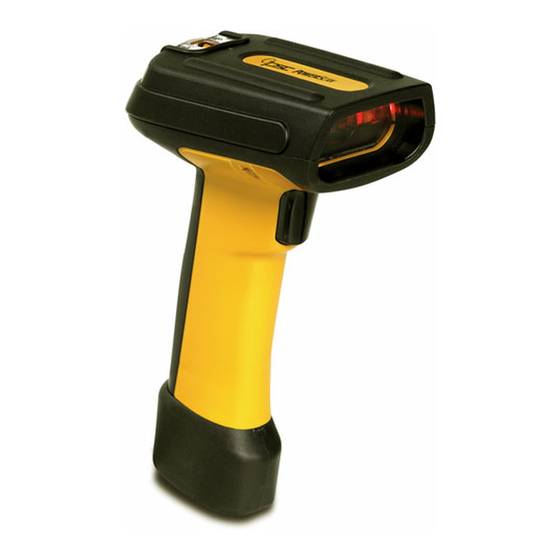
Chapter 1 Getting Started ® The PowerScan 7000 2D imager marks a new performance level for handheld area imagers. They deliver aggressive read rates and depths of field on 1D, stacked linear, and matrix codes. This aggressiveness applies even in challenging reading environments where low lighting conditions and poor quality might make it difficult to read bar codes. -
Page 11: Manual Conventions
Getting Started Manual Conventions The symbols listed below are used in this manual to notify the reader of key issues or procedures that must be observed when using the imager: Notes contain information necessary for prop- erly diagnosing, repairing and operating the imager. -
Page 12: Led And Beeper Indications
LED and Beeper Indications LED and Beeper Indications The imager is equipped with a beeper (speaker) and two indicator LEDs; one green and one yellow. These indicators “beep” or flash when certain actions take place: Some LED and Beeper indications are user-con- figurable for volume, pitch, quantity, duration, enable/disable, etc. -
Page 13: Plug And Play
Getting Started Plug and Play Plug and Play bar codes provide instant imager set up for commonly used interfaces. After you scan one of the codes, power cycle the host terminal to have the interface in effect. NOTE Connecting the imager with an RS-232 Serial Port These instructions are for use with the RS-232 cable. -
Page 14: Connecting The Imager With Usb
Plug and Play 3. Plug the serial connector into the serial port on your computer. Tighten the two screws to secure the connector to the port. 4. If the terminal does not support Power Off the Terminal (P.O.T.) connections plug the power supply into the host connector and the AC outlet. -
Page 15: Ibm Surepos
Getting Started 2. The imager beeps. 3. Verify imager operation by scanning the part number bar code from the back cover of this manual. The following USB “Plug and Play” codes are supported on specific models. Refer to the Product Reference Guide to determine if this interface applies to your unit. -
Page 16: Usb Pc Keyboard Or Usb Macintosh Keyboard
Plug and Play Each bar code above also programs the following suffixes for each sym- bology: Symbology Suffix EAN-8 EAN-13 UPC-A UPC-E Code 39 00 0A 0B Interleaved 2 of 5 00 0D 0B Code 128 00 18 0B The following USB “Plug and Play” codes (USB Keyboard - PC, USB Keyboard - Mac, and USB HID) are supported on specific imager models. -
Page 17: Usb Hid
Getting Started USB HID Scan the following code to program the imager for USB HID bar code imagers. Scanning this code changes the terminal ID to 131. USB HID Bar Code imager USB COM Port Emulation Scan the following code to program the imager to emulate a regular RS- ®... -
Page 18: Ack/Nak Mode
The Universal Keyboard Wedge (UKBW) model allows an RS-232 transmission or Keyboard Wedge mode according to the type of cable connected. Contact Datalogic or your dealer for cable and/or power sup- ply part numbers. 1. Turn off power to the terminal/computer. -
Page 19: Getting Started
Getting Started 3. Connect one end of the Y cable to the keyboard cable and the other to the keyboard port on the host/computer. Cable Connector Retainer Boss Captive Screws 4. Scan the following bar code to program the imager for the UKBW interface. -
Page 20: Chapter 2 Terminal Interfaces
Chapter 2 Terminal Interfaces Use this section to configure interface features for imager models using RS-232 and USB inter- faces. For Imager models using UKBW interfaces, do NOTE not use this section but refer to the UKBW Con- nectivity Guide available for download from the website listed on the back over of this manual. -
Page 21: Supported Terminals
Terminal Interfaces For example, an IBM AT terminal has a Terminal ID of 003. You would scan the bar code, then from the Terminal ID Programming Chart on of this manual, then . If you make an error while scanning Save page B-5 the digits (before scanning Save), scan the... -
Page 22: Keyboard Country
Keyboard Country Keyboard Country Scan the appropriate country code below to program the keyboard for your country. As a general rule, the following characters are supported, but need special care for countries other than the United States: @ | $ # { } [ ] = / ‘ \ < > ~ * United States Belgium Brazil... - Page 23 Terminal Interfaces Keyboard Country (continued) Italy Latin America Netherlands (Dutch) Norway Poland Portugal Romania Russia Slovakia Spain Sweden Switzerland (German) ® PowerScan 7000 2D...
-
Page 24: Keyboard Style
Keyboard Style Keyboard Country (continued) Turkey F Turkey Q U.K. Keyboard Style This programs keyboard styles, such as Caps Lock and Shift Lock. Default = Regular. Regular is used when you normally have the Caps Lock key off. * Regular Caps Lock is used when you normally have the Caps Lock key on. -
Page 25: Terminal Interfaces
Terminal Interfaces Automatic Caps Lock is used if you change the Caps Lock key on and off. The software tracks and reflects if you have Caps Lock on or off (AT and PS/2 only). This selection can only be used with systems that have an LED which notes the Caps Lock status. -
Page 26: Keyboard Modifiers
Keyboard Modifiers Keyboard Modifiers This modifies special keyboard features, such as CTRL+ ASCII codes and Turbo Mode. Control + ASCII Mode On The Imager sends key combinations for ASCII control characters for val- ues 00-1F. Refer to Keyboard Function Relationships on page 9-1 CTRL+ ASCII Values. -
Page 27: Rs-232 Modifiers
Terminal Interfaces RS-232 Modifiers RS-232 Baud Rate Baud Rate sends the data from the imager to the terminal at the specified rate. The host terminal must be set for the same baud rate as the imager. Default = 115,200. 1200 2400 4800 9600... -
Page 28: Word Length: Data Bits, Stop Bits, And Parity
RS-232 Modifiers RS-232 Word Length: Data Bits, Stop Bits, and Parity Data Bits sets the word length at 7 or 8 bits of data per character. If an application requires only ASCII Hex characters 0 through 7F decimal (text, digits, and punctuation), select 7 data bits. For applications which require use of the full ASCII set, select 8 data bits per character. -
Page 29: Rs-232 Receiver Time-Out
Terminal Interfaces RS-232 Receiver Time-Out The unit stays awake to receive data until the RS-232 Receiver Time- Out expires. A manual or serial trigger resets the time-out. When an RS-232 receiver is sleeping, a character may be sent to wake up the receiver and reset the time-out. -
Page 30: Rs-232 Handshaking
RS-232 Modifiers RS-232 Handshaking RS-232 handshaking is a set of rules concerning the exchange of data between serially communicating devices. If using RTS/CTS handshaking, the imager issues an active RTS signal to the receiving device. The imager waits to send its data until it detects an active CTS signal from the receiving device. - Page 31 Terminal Interfaces NOTES ® 2-12 PowerScan 7000 2D...
-
Page 32: Chapter 3 Output
Chapter 3 Output Image VGA You can set the image size to a VGA resolution, if necessary, to accom- modate older applications that require a smaller image size. When Image VGA is set to On, the resultant image is 640x480 pixels. When Image VGA is Off, your image is 752x480 pixels. -
Page 33: Beeper Volume - Good Read
Output Beeper Volume – Good Read The beeper volume codes modify the volume of the beep the imager emits on a good read. Default = Medium. * Medium High Beeper Pitch – Good Read The beeper pitch codes modify the pitch (frequency) of the beep the imager emits on a good read. -
Page 34: Beeper Duration - Good Read
Good Read Indicators Beeper Duration – Good Read The beeper duration codes modify the length of the beep the imager emits on a good read. Default = Normal. * Normal Beep Short Beep LED – Good Read The LED indicator can be programmed On or Off in response to a good read. -
Page 35: Good Read Delay
Output Good Read Delay This sets the minimum amount of time before the imager can read another bar code. Default = No Delay. * No Delay Short Delay (500 ms) Medium Delay (1,000 ms) Long Delay (1,500 ms) User-Specified Good Read Delay If you want to set your own length for the good read delay, scan the bar code below, then set the delay (from 0-30,000 milliseconds) by scanning digits from the... -
Page 36: Read Time-Out
Trigger Modes When in serial mode, the imager scans until a bar code has been read or until the deactivate command is sent. In serial mode, the imager can also be set to turn itself off after a specified time has elapsed (see Read Time- , which follows). - Page 37 Output If the unit remains idle during the low power time-out interval, the unit goes into low power mode. Whenever the trigger is enabled, the low power time-out timer is reset. Low Power Time-Out This time-out does not begin until the imager time-out setting has expired.
-
Page 38: Scan Stand Mode
Scan Stand Mode Scan Stand Mode When a unit is in Scan Stand mode, it remains idle as long as it sees the Scan Stand symbol. (See that follows.) When a dif- Scan Stand Symbol ferent code is presented, the Imager is triggered to read the new code. Note:The imager automatically adjusts the illumination LEDs to the lowest light level possible to maintain a good lock on the Scan Stand symbol. -
Page 39: Presentation Led Timer
Output Presentation LED Timer When an imager is in presentation mode, the LEDs turn off immediately after a bar code is decoded. The imager can be programmed to continue scanning and to keep the LEDs on for a short time after by scanning the LEDs On bar code below. -
Page 40: Double Read Timeout
Double Read Timeout Scan the Hands Free Time-Out bar code, then scan the time-out duration (from 0-300,000 milliseconds) from the Programming Chart on page B-5 and Save. Default = 5,000 ms. Hands Free Time-Out Double Read Timeout This sets the time period before the imager can read the same bar code a second time. -
Page 41: Led Power Level
Output LED Power Level This selection allows you to adjust LED and aimer brightness. Off is used when no illumination is needed. Low is used if low illumination is sufficient. High (the default) is the brightest setting. If you have an aimer delay programmed (see Aimer Delay on page 3-12 the aimer will be at 100% power during the delay, regardless of the LED Power Level. -
Page 42: Illumination Lights
Illumination Lights Illumination Lights If you want the illumination lights on while reading a bar code, scan the Lights On bar code, below. However, if you want to turn just the lights off, scan the Lights Off bar code. This setting does not affect the aimer light. The aiming light can be set using Aimer Mode (see Aimer Modes on page 3-13 NOTE... -
Page 43: Aimer Delay
Output Aimer Delay The aimer delay allows a delay time for the operator to aim the imager before the picture is taken. Use these codes to set the time between when the trigger is pulled and when the picture is taken. During the delay time, the aiming light will appear, but the LEDs won’t turn on until the delay time is over. -
Page 44: Aimer Modes
Aimer Modes Aimer Modes This feature allows you to select from the three options listed below: Aimer Mode Off Aimer Mode is disabled. Interlaced Mode In Interlaced Mode, the illumination and aiming timing is automatically synchronized to the imager exposure period by the Optics Module. The module turns illumination on while the image is being exposed, and it turns the aiming off at all other times. -
Page 45: Centering
Output duty cycle, even when the imager exposure time is at its maximum in dark operating environments. Concurrent mode provides the brightest appearance of the illumination LEDs of any of the imager operating modes. This mode may be useful for applications when an operator is using the illumination LEDs for aiming, such as in fixed mount, kiosk, or auto trigger applications. -
Page 46: Product Reference Guide
Centering In the example in , the gray area is the full imager field of view Figure 3-1 and the white area is the centering window. Bar Code 1 will not be read, while Bar Code 2 will be.The default centering window is a 128x96 pixel area in the center of the imager’s field of view. -
Page 47: Decode Search Mode
Output Scan Centering On, then scan one of the following bar codes to change the top, bottom, left, or right of the centering window. Then scan the percent you want to shift the centering window using digits on the Pro- . -
Page 48: Output Sequence Overview
Output Sequence Overview Quick Omnidirectional - This is an abbreviated search for bar code fea- tures around the center region of an image. This mode quickly reads all symbologies in any orientation. The Quick Omnidirectional mode may miss some off-center symbols, as well as larger Data Matrix and QR Code symbols. -
Page 49: Output Sequence Editor
Output Output Sequence Editor This programming selection allows you to program the Imager to output data (when scanning more than one symbol) in whatever order your application requires, regardless of the order in which the bar codes are scanned. Reading the Default Sequence symbol programs the Imager to the Universal values, shown below. -
Page 50: Other Programming Selections
Output Sequence Overview 5. End Output Sequence Editor Scan F F to enter an Output Sequence for an additional symbol- ogy, or Save to save your entries. Other Programming Selections Discard This exits without saving any Output Sequence changes. Output Sequence Examples In this example, you are scanning Code 93, Code 128, and Code 39 bar codes, but you want the imager to output Code 39 1st, Code 128 2nd, and Code 93 3rd, as shown below. - Page 51 Output The breakdown of the command line is shown below: SEQBLK sequence editor start command code identifier for Code 39 9999 code length that must match for Code 39, 9999 = all lengths start character match for Code 39, 41h = “A” termination string for first code code identifier for Code 128 9999...
-
Page 52: Output Sequence Editor
Output Sequence Overview Output Sequence Editor Enter Sequence Default Sequence Require Output Sequence When an output sequence is Required, all output data must conform to an edited sequence or the imager will not transmit the output data to the host device. When it’s On/Not Required, the imager will attempt to get the output data to conform to an edited sequence, but if it cannot, the imager transmits all output data to the host device as is. -
Page 53: Multiple Symbols
Output Multiple Symbols This feature does not work when the Imager is in Low Power mode. NOTE When this programming selection is turned On, it allows you to read multiple symbols with a single pull of the Imager’s trigger. If you press and hold the trigger, aiming the Imager at a series of symbols, it reads unique symbols once, beeping (if turned on) for each read. -
Page 54: Print Weight
Print Weight Print Weight Print Weight is used to adjust the way the imager reads Matrix symbols. If a imager will be seeing consistently heavily printed matrix symbols, then a print weight of 6 may improve the reading performance. For con- sistently light printing, a print weight of 2 may help. -
Page 55: Working Orientation
Output Working Orientation Some bar codes are direction-sensitive. For example, KIX codes and OCR can misread when scanned sideways or upside down. Use the working orientation settings if your direction-sensitive codes will not usually be presented upright to the scanner. Default = Upright. Upright: Rotate Clockwise 90°: Upside Down:... -
Page 56: Chapter 4 Data Editing
Chapter 4 Data Editing For Universal Keyboard Wedge (UKBW) inter- faces do not use this section. Refer instead to the Universal Keyboard Wedge Programming Guide which is available for download from the website listed on the back cover of this manual. NOTE Prefix/Suffix Overview When a bar code is scanned, additional information is sent to the host... -
Page 57: Points To Keep In Mind
Data Editing Points to Keep In Mind • It is not necessary to build a message string. The selections in this chapter are only used if you wish to alter the default settings. Default prefix = None. Default suffix = None. •... -
Page 58: To Add A Prefix Or Suffix
Prefix/Suffix Overview To Add a Prefix or Suffix: Step 1. Scan the Add Prefix or Add Suffix symbol (page 4-5). Step 2. Determine the 2 digit Hex value from the Symbology Chart (included in the Symbology Chart on page A-1) for the symbology to which you want to apply the prefix or suffix. -
Page 59: Example: Add A Suffix To A Specific Symbology
Data Editing Example: Add a Suffix to a specific symbology To send a CR (carriage return)Suffix for UPC only: Step 1. Scan Add Suffix. Step 2. Determine the 2 digit hex value from the Symbology Chart (included ASCII Conversion Chart (Code Page 1252) on page A-4) for UPC. -
Page 60: Prefix Selections
Prefix/Suffix Overview Prefix Selections Add Prefix Clear One Prefix Clear All Prefixes Suffix Selections Add Suffix Clear One Suffix Clear All Suffixes Function Code Transmit When this selection is enabled and function codes are contained within the scanned data, the imager transmits the function code to the terminal. Charts of these function codes are provided in Supported Interface Keys . -
Page 61: Intercharacter, Interfunction, And Intermessage Delays
Data Editing Intercharacter, Interfunction, and Intermessage Delays Some terminals drop information (characters) if data comes through too quickly. Intercharacter, interfunction, and intermessage delays slow the transmission of data, increasing data integrity. Each delay is composed of a 5 millisecond step. You can program up to 99 steps (of 5 ms each) for a range of 0-495 ms. -
Page 62: User Specified Intercharacter Delay
Intercharacter, Interfunction, and Intermessage Delays User Specified Intercharacter Delay An intercharacter delay of up to 495 milliseconds may be placed after the transmission of a particular character of scanned data. Scan the Delay Length bar code below, then scan the number of milliseconds and the SAVE bar code using the of this manual. -
Page 63: Intermessage Delay
Data Editing Intermessage Delay An intermessage delay of up to 495 milliseconds may be placed between each scan transmission. Scan the Intermessage Delay bar code below, then scan the number of milliseconds and the SAVE bar code using the of this manual. Programming Chart on page B-5 1st Scan Transmission 2nd Scan Transmission... -
Page 64: Chapter 5 Data Formatting
Chapter 5 Data Formatting Data Format Editor Introduction You may use the Data Format Editor to change the imager’s output. For example, you can use the Data Format Editor to insert characters at cer- tain points in bar code data as it is scanned. The selections in the follow- ing pages are used only if you wish to alter the output. -
Page 65: Powerscan® 7000 2D
Data Formatting To Add a Data Format Step 1. Scan the Enter Data Format symbol (page 5-5). Step 2. Primary/Alternate Format Determine if this will be your primary data format, or one of 3 alternate formats. (Alternate formats allow you “single shot” capability to scan one bar code using a different data format. -
Page 66: Other Programming Selections
Data Format Editor Introduction bols that represent the command you want to enter. 94 alphanumeric characters may be entered for each symbology data format. Step 7. Scan Save from the Programming Chart on page B-5 of this manual to save your entries. Other Programming Selections Clear One Data Format —... -
Page 67: Move Commands
Data Formatting Move Commands F5 Move the cursor ahead “nn” characters from current cursor position. Syntax = F5nn (nn stands for the numeric value (00-99) for the number of characters the cursor should be moved ahead.) F6 Move the cursor back “nn” characters from current cursor position. Syntax = F6nn (nn stands for the numeric value (00-99) for the number of characters the cursor should be moved back.) F7 Move the cursor to the beginning of the data string. -
Page 68: Data Format Editor
Data Format Editor Introduction ED Check to make sure there is a non-numeric ASCII character at the current cursor position. If character is numeric, format is aborted. Syntax = ED. D ata Form at Editor Enter Data Format * Default Data Format Clear One Data Format Clear All Data Formats Save... -
Page 69: Alternate Data Formats
Data Formatting Alternate Data Formats Alternate formats allow you “single shot” capability to scan one bar code using a different data format than your primary format. When data for- mats are programmed (see ), you must input whether you are page 5-2 programming the primary format, or an alternate format numbered 1, 2, or 3. -
Page 70: Chapter 6 Symbologies
Chapter 6 Symbologies This programming section contains the following menu selections. Refer to for settings and defaults. Chapter 10 ·Linear Symbologies ·Japanese Post ·Australian Post ·Kix (Netherlands) Post ·Aztec Code Enable ·Korea Post ·British Post ·Matrix 2 of 5 Enable ·Canadian Post ·MaxiCode Enable ·China Post Enable... -
Page 71: Linear Symbologies
Symbologies Linear Symbologies All Symbologies If you want to decode all the symbologies allowable for your imager, scan the All Symbologies On code. If on the other hand, you want to decode only a particular symbology, scan All Symbologies Off followed by the On symbol for that particular symbology. -
Page 72: Codabar Enable
Linear Symbologies Codabar <Default All Codabar Settings> Codabar Enable * On Codabar Start/Stop Characters Start/Stop characters identify the leading and trailing ends of the bar code. You may either transmit, or not transmit Start/Stop characters. Default = Don’t Transmit. Transmit * Don’t Transmit Codabar Check Character Codabar check characters are created using different “modulos.”... -
Page 73: Codabar Concatenation
Symbologies When Check Character is set to Validate, but Don’t Transmit, the unit will only read Codabar bar codes printed with a check character, but will not transmit the check character with the scanned data. * No Check Character Validate Modulo 16, but Don’t Transmit Validate Modulo 16 and Transmit... -
Page 74: Codabar Message Length
Linear Symbologies Codabar Message Length Scan the bar codes below to change the message length. Refer to Mes- for additional information. Mini- sage Length Description on page 6-2 mum and Maximum lengths = 2-60. Minimum Default = 4, Maximum Default = 60. Minimum Message Length Maximum Message Length Code 39... -
Page 75: Code 39 Check Character
Symbologies Code 39 Check Character indicates that the imager reads and transmits bar code No Check Character data with or without a check character. When Check Character is set to , the unit only Validate, but Don’t Transmit reads Code 39 bar codes printed with a check character, but will not transmit the check character with the scanned data. - Page 76 Linear Symbologies Code 39 Append This function allows the imager to append the data from several Code 39 bar codes together before transmitting them to the host computer. When this function is enabled, the imager stores those Code 39 bar codes that start with a space (excluding the start and stop symbols), and does not immediately transmit the data.
-
Page 77: Full Ascii
Symbologies Full ASCII If Full ASCII Code 39 decoding is enabled, certain character pairs within the bar code symbol will be interpreted as a single character. For example: $V will be decoded as the ASCII character SYN, and /C will be decoded as the ASCII character #. -
Page 78: Interleaved 2 Of 5
Linear Symbologies Code 39 Code Page Code pages define the mapping of character codes to characters. If the data received does not display with the proper characters, it may be because the bar code being scanned was created using a code page that is different from the one the host program is expecting. -
Page 79: Interleaved 2 Of 5 Message Length
Symbologies When Check Digit is set to , the imager only reads Validate and Transmit Interleaved 2 of 5 bar codes printed with a check digit, and will transmit this digit at the end of the scanned data. Default = No Check Digit. * No Check Digit Validate, but Don’t Transmit Validate and Transmit... -
Page 80: Code 93 Enable
Linear Symbologies Code 93 < Default All Code 93 Settings > Code 93 Enable * On Code 93 Message Length Scan the bar codes below to change the message length. Refer to Mes- for additional information. Mini- sage Length Description on page 6-2 mum and Maximum lengths = 0-80. -
Page 81: Code 2 Of 5
Symbologies Code 2 of 5 <Default All Code 2 of 5 Settings> Code 2 of 5 Enable * Off Code 2 of 5 Message Length Scan the bar codes below to change the message length. Refer to Mes- for additional information. Mini- sage Length Description on page 6-2 mum and Maximum lengths = 1-48. -
Page 82: Iata Code 2 Of 5
Linear Symbologies IATA Code 2 of 5 <Default All Code IATA 2 of 5 Settings> IATA Code 2 of 5 Enable * Off IATA Code 2 of 5 Message Length Scan the bar codes below to change the message length. Refer to Mes- for additional information. -
Page 83: Matrix 2 Of 5
Symbologies M atrix 2 o f 5 <Default All Matrix 2 of 5 Settings> Matrix 2 of 5 Enable * Off Matrix 2 of 5 Message Length Scan the bar codes below to change the message length. Refer to Mes- for additional information. -
Page 84: Check Digits Required
Linear Symbologies Check Digits Required This option sets whether 1 or 2 check digits are required with Code 11 bar codes. Default = Two Check Digits. One Check Digit * Two Check Digits Code 11 Message Length Scan the bar codes below to change the message length. Refer to Mes- for additional information. -
Page 85: Code 128
Symbologies Code 128 <Default All Code 128 Settings> Code 128 Enable * On ISBT 128 Concatenation In 1994 the International Society of Blood Transfusion (ISBT) ratified a standard for communicating critical blood information in a uniform manner. The use of ISBT formats requires a paid license. The ISBT 128 Application Specification describes 1) the critical data elements for label- ing blood products, 2) the current recommendation to use Code 128 due to its high degree of security and its space-efficient design, 3) a varia-... -
Page 86: Code 128 Message Length
Linear Symbologies Code 128 Message Length Scan the bar codes below to change the message length. Refer to Mes- for additional information. Mini- sage Length Description on page 6-2 mum and Maximum lengths = 0-80. Minimum Default = 0, Maximum Default = 80. -
Page 87: Telepen Output
Symbologies Telepen * Off Telepen Output Using AIM Telepen Output, the imager reads symbols with start/stop pattern 1 and decodes them as standard full ASCII (start/stop pattern 1). When Original Telepen Output is selected, the imager reads symbols with start/stop pattern 1 and decodes them as compressed numeric with optional full ASCII (start/stop pattern 2). -
Page 88: Upc-A
Linear Symbologies UPC-A <Default All UPC-A Settings> UPC-A Enable * On UPC-A Check Digit Transmit This selection allows you to specify whether the check digit should be transmitted at the end of the scanned data or not. Default = On. * On UPC-A Number System The numeric system digit of a U.P.C. - Page 89 Symbologies UPC-A Addenda This selection adds 2 or 5 digits to the end of all scanned UPC-A data. Default = Off for both 2 Digit and 5 Digit Addenda. 2 Digit Addenda On * 2 Digit Addenda Off 5 Digit Addenda On * 5 Digit Addenda Off UPC-A Addenda Required When Required is scanned, the imager will only read UPC-A bar codes...
-
Page 90: Upc-A/Ean-13
Linear Symbologies UPC-A/EAN-13 with Extended Coupon Code Use the following codes to enable or disable UPC-A and EAN-13 with Extended Coupon Code. Default = On. * On UPC-E0 <Default All UPC-E Settings> UPC-E0 Most U.P.C. bar codes lead with the 0 number system. For these codes, use the UPC-E0 selection. - Page 91 Symbologies UPC-E0 Addenda Required When Addenda Required is set to on, the imager will only read UPC-E bar codes that have addenda. Default = Not Required. Required * Not Required UPC-E0 Addenda Separator When this feature is on, there is a space between the data from the bar code and the data from the addenda.
- Page 92 Linear Symbologies UPC-E0 Number System The numeric system digit of a U.P.C. symbol is normally transmitted at the beginning of the scanned data, but the unit can be programmed so it will not transmit it. Default = On. * On UPC-E0 Addenda This selection adds 2 or 5 digits to the end of all scanned UPC-E data.
-
Page 93: Ean/Jan-13
Symbologies EAN/JAN-13 <Default All EAN/JAN Settings> EAN/JAN-13 Enable * On EAN/JAN-13 Check Digit Transmit This selection allows you to specify whether the check digit should be transmitted at the end of the scanned data or not. Default = On. * On EAN/JAN-13 Addenda This selection adds 2 or 5 digits to the end of all scanned EAN/JAN-13 data. -
Page 94: Isbn Translate
Linear Symbologies EAN/JAN-13 Addenda Required When Addenda Required is set to on, the imager will only read EAN/ JAN-13 bar codes that have addenda. Default = Not Required. Required * Not Required EAN/JAN-13 Addenda Separator When this feature is on, there is a space between the data from the bar code and the data from the addenda. -
Page 95: Ean/Jan-8
Symbologies EAN/JAN-8 <Default All EAN/JAN-8 Settings> EAN/JAN-8 Enable * On EAN/JAN-8 Check Digit Transmit This selection allows you to specify whether the check digit should be transmitted at the end of the scanned data or not. Default = On. * On EAN/JAN-8 Addenda This selection adds 2 or 5 digits to the end of all scanned EAN/JAN-8 data. - Page 96 Linear Symbologies EAN/JAN-8 Addenda Required When Addenda Required is set to on, the imager will only read EAN/ JAN-8 bar codes that have addenda. Default = Not Required. Required * Not Required EAN/JAN-8 Addenda Separator When this feature is on, there is a space between the data from the bar code and the data from the addenda.
-
Page 97: Msi
Symbologies <Default All MSI Settings> MSI Enable * Off MSI Check Character Different types of check characters are used with MSI bar codes. You can program the imager to read MSI bar codes with Type 10 check char- acters. Default = Validate Type 10, but Don’t Transmit. When Check Character is set to Validate and Transmit, the imager will only read MSI bar codes printed with the specified type check character, and will transmit this character at the end of the scanned data. -
Page 98: Msi Message Length
Linear Symbologies MSI Message Length Scan the bar codes below to change the message length. Refer to Mes- for additional information. Mini- sage Length Description on page 6-2 mum and Maximum lengths = 4-48. Minimum Default = 4, Maximum Default = 48. Minimum Message Length Maximum Message Length Plessey Code... -
Page 99: Rss Limited
Symbologies RSS-14 < Default All RSS-14 Settings > RSS-14 Enable * On RSS Limited < Default All RSS Limited Settings > RSS Limited Enable * On ® 6-30 PowerScan 7000 2D... -
Page 100: Rss Expanded
Linear Symbologies RSS Expanded < Default All RSS Expanded Settings > RSS Expanded Enable * On RSS Expanded Message Length Scan the bar codes below to change the message length. Refer to Mes- for additional information. Mini- sage Length Description on page 6-2 mum and Maximum lengths = 4-74. -
Page 101: Posicode
Symbologies PosiCode <Default All PosiCode Settings> PosiCode A and B Enable * On You have to have PosiCode A and B on to read any of the PosiCode sym- bologies. A and B On (No Limited) A and B and Limited A On (Limited B Off) * A and B and Limited B On (Limited A Off) -
Page 102: Trioptic Code
Stacked Symbologies Trioptic Code If you are going to scan Code 32 Pharmaceuti- cal codes ( ), Trioptic Code must be off. page 6-7 NOTE Trioptic Code is used for labeling magnetic storage media. * Off Stacked Symbologies Codablock F <Default All Codablock F Settings>... -
Page 103: Code 16K
Symbologies Code 16K <Default All Code 16K Settings> Code 16K Enable * Off Code 16K Message Length Scan the bar codes below to change the message length. Refer to Mes- for additional information. Mini- sage Length Description on page 6-2 mum and Maximum lengths = 0-160. -
Page 104: Code 49
Stacked Symbologies Code 49 <Default All Code 49 Settings> Code 49 Enable * On Code 49 Message Length Scan the bar codes below to change the message length. Refer to Mes- for additional information. Mini- sage Length Description on page 6-2 mum and Maximum lengths = 1-81. -
Page 105: Pdf417
Symbologies PDF417 < Default All PDF417 Settings > PDF417 Enable * On PDF417 Message Length Scan the bar codes below to change the message length. Refer to Mes- for additional information. Mini- sage Length Description on page 6-2 mum and Maximum lengths = 1-2750. Minimum Default = 1, Maximum Default = 2750. -
Page 106: Micropdf417
Stacked Symbologies MicroPDF417 < Default All MicroPDF417 Settings > MicroPDF417 Enable * Off MicroPDF417 Message Length Scan the bar codes below to change the message length. Refer to Mes- for additional information. Mini- sage Length Description on page 6-2 mum and Maximum lengths = 1-366. Minimum Default = 1, Maximum Default = 366. -
Page 107: Upc/Ean Version
Symbologies UPC/EAN Version Scan the UPC/EAN Version On bar code to decode EAN•UCC Compos- ite symbols that have a UPC or EAN linear component. (This does not affect EAN•UCC Composite symbols with a UCC/EAN-128 or RSS linear component.) UPC/EAN Version On * UPC/EAN Version Off EAN•UCC Composite Code Message Length Scan the bar codes below to change the message length. -
Page 108: Tcif Linked Code 39 (Tlc39)
Stacked Symbologies tion is selected, the AIM Symbology Identifier is reported as “]C1”. If RSS Emulation is selected, the AIM Symbology Identifier is reported as “]e0.” Any application that accepts EAN•UCC data can be simplified since it only needs to recognize one data carrier type. Default = No Emu- lation. -
Page 109: Postal Codes
Symbologies Postal Codes For best performance when reading a postal symbology, all other postal symbologies should be turned off. The following postal codes can only be read by a full 2D Imager. NOTE Postnet * Off Postnet Check Digit Transmit This selection allows you to specify whether the check digit should be transmitted at the end of the scanned data. -
Page 110: Planet Code
Postal Codes Planet Code * Off Planet Code Check Digit Transmit This selection allows you to specify whether the check digit should be transmitted at the end of the scanned data. Transmit Check Digit * Don’t Transmit Check Digit Product Reference Guide 6-41... -
Page 111: British Post
Symbologies British Post * Off Canadian Post * Off Kix (Netherlands) Post Kix code can misread when scanned sideways or upside down. Use Working Orientation, page 3-19, if your Kix codes will not usually be pre- sented upright to the scanner. NOTE * Off ®... -
Page 112: Australian Post
Postal Codes Australian Post * Off Japanese Post * Off China Post <Default All China Post Settings> Product Reference Guide 6-43... -
Page 113: Korea Post
Symbologies China Post Enable * Off China Post Message Length Scan the bar codes below to change the message length. Refer to Mes- for additional information. Mini- sage Length Description on page 6-2 mum and Maximum lengths = 2-80. Minimum Default = 4, Maximum Default = 80. -
Page 114: Qr Code
Postal Codes Korea Post * Off Korea Post Message Length Scan the bar codes below to change the message length. Refer to Mes- for additional information. Mini- sage Length Description on page 6-2 mum and Maximum lengths = 2-80. Minimum Default = 4, Maximum Default = 48. -
Page 115: Data Matrix
Symbologies QR Code This selection applies to both QR Code and Micro QR Code. * Off QR Code Message Length Scan the bar codes below to change the message length. Refer to Mes- for additional information. Mini- sage Length Description on page 6-2 mum and Maximum lengths = 1-3500. -
Page 116: Maxicode
Postal Codes Data Matrix Enable * On Data Matrix Message Length Scan the bar codes below to change the message length. Refer to Mes- for additional information. Mini- sage Length Description on page 6-2 mum and Maximum lengths = 1-1500. Minimum Default = 1, Maximum Default = 1500. -
Page 117: Maxicode Message Length
Symbologies MaxiCode Enable * On MaxiCode Message Length Scan the bar codes below to change the message length. Refer to Mes- for additional information. Mini- sage Length Description on page 6-2 mum and Maximum lengths = 1-150. Minimum Default = 1, Maximum Default = 150. -
Page 118: Aztec Runes
Postal Codes Aztec Code Enable * On Aztec Code Message Length Scan the bar codes below to change the message length. Refer to Mes- for additional information. Mini- sage Length Description on page 6-2 mum and Maximum lengths = 1-3750. Minimum Default = 1, Maximum Default = 3750. - Page 119 Symbologies NOTES ® 6-50 PowerScan 7000 2D...
-
Page 120: Chapter 7 Imaging Commands
Chapter 7 Imaging Commands The imager can be used as a digital camera for capturing, manipulating, and transferring images. Imaging Commands with their modifiers send imaging commands to the imager on a single-use basis, and take effect for the next subsequent image capture. -
Page 121: Imgsnp Modifiers
Imaging Commands IMGSNP Modifiers P - Imaging Style: Sets the Image Snap style. 0P Decoding Style. This is similar to the current format for decoding, however, this processing allows a few frames to be taken until the exposure parameters are met. Then the last frame is available for further use. - Page 122 Image Snap - IMGSNP nD Range: 0 - 255 L - LED State: Determines if the LEDs should be on or off, and when. Ambient illumination (0L) is preferred for taking pictures of color docu- ments, such as ID cards, especially when the imager is in a stand. LED illumination (1L) is preferred when the imager is hand held.
-
Page 123: Image Ship - Imgshp
Imaging Commands Image Ship - IMGSHP An image is taken whenever the trigger of the unit is pressed, or when the Image Snap (IMGSNP) command is processed. The last image is always stored in memory. You may “ship” the image by using the IMG- SHP command. - Page 124 Image Ship - IMGSHP E - Edge Sharpen: Causes the transmitted image to be convolved with an edge sharpening filter. Entering a 23E gives the sharpest edges, but also increases noise in the image. 0E Don’t sharpen image (default) 14E Apply edge sharpen for typical image Apply edge sharpen using strength n (n = 1-24) F - File Format: Indicates the desired format for the image.
- Page 125 Imaging Commands IR - Image Rotate: 1IR Rotate image 90 degrees to the right 2IR Rotate image 180 degrees (upside down) 3IR Rotate image 90 degrees to the left J - JPEG Image Quality: Sets the desired quality when the JPEG image format is selected.
- Page 126 Image Ship - IMGSHP nR The right edge of the shipped image corresponds to column n - 1 of the image in memory. Range: 000 - 640. (Default = all columns, or 639 for VGA imager) nT The top edge of the shipped image corresponds to row n of the image in memory.
- Page 127 Imaging Commands 3S ship every 3rd pixel, both horizontally and vertically U - Document Image Filter: Sharpens the edges and smooths the area between the edges of the transmitted text image. The Document Image Filter enhances images of documents such as ID cards and prescriptions. This filter should be used with gamma correction (see page 7-6), with...
-
Page 128: Intelligent Signature Capture - Imgbox
Intelligent Signature Capture - IMGBOX Intelligent Signature Capture - IMGBOX Intelligent signature capture ships only part of an image to the host application. This method reduces transfer time and file size, while sim- plifying signature capture. Below is an example of an intelligent signature capture application. In this example, the operator reads the bar code, which is then transmitted to the host application. -
Page 129: Imgbox Modifiers
Imaging Commands IMGBOX Modifiers D - Pixel Depth: Indicates the number of bits per pixel in the transmit- ted image. 8D 8 bits per pixel, grayscale image 1D 1 bit per pixel, black and white image F - File Format: Indicates the type of file format in which to save the image. - Page 130 Intelligent Signature Capture - IMGBOX 50K Apply gamma correction for brightening typical document image nK Apply gamma correction factor n (n = 1-255) R - Resolution of Signature Capture Area: The number of pixels that the imager outputs per each minimum bar width. The higher the value for R, the higher the quality of the image, but also the larger the file size.
- Page 131 Imaging Commands NOTES ® 7-12 PowerScan 7000 2D...
-
Page 132: Chapter 8 Ocr Programming
Chapter 8 OCR Programming Use this section to program the Imager for optical character recognition (OCR). PowerScan 2D models read 6 to 60 point OCR typeface. OCR is not as secure as bar codes. To enhance security in OCR applications, create an OCR template to match the data, and print an OCR check character. -
Page 133: Ocr Fonts
OCR Programming You can either select an OCR default, or create your own custom tem- plate for the type of OCR format you intend to read. See OCR on page 8- for programming codes that will enable your imager to read OCR-A, OCR-B, U.S. -
Page 134: U.s. Currency Font
OCR Fonts allows you to scan characters in the OCR-A font. The default OCR-A On setting allows you to scan any eight digit combination. If you have cre- ated an OCR template, character combinations that fit the template can be scanned (see Creating an OCR Template on page 8-5 OCR-A On allows you to scan characters in the OCR-B font. -
Page 135: Micr E13 B Font
OCR Programming MICR E13 B Font allows you to scan MICR characters on a bank check. MICR E13 B On The default setting allows you to scan any eight digit combination. If you have created an OCR template, character combinations that fit the template can be scanned (see Creating an OCR Template on page 8-5 MICR E 13 B On... -
Page 136: Ocr Templates
OCR Templates OCR Templates You can create a custom “template,” or character string that defines the length and content of OCR strings that will be read with your imager. There are several choices when creating a custom template for your application. -
Page 137: Template Characters
OCR Programming Template Characters Table 8-1. Template Characters represents any alphanumeric character (digit or letter) represents a check character position represents any digit represents any available OCR character represents character from user-defined variable “g” represents character from user-defined variable “h” represents any uppercase letter marks the start of a new template multi row indicator... -
Page 138: Character Match Sequences
OCR Templates You need to read any combination of eight digits. The template would be: dddddddd To create this template, you would enable the OCR-A font. Scan the symbol ( ), then scan the from the Enter OCR Template page 8-16 eight times. -
Page 139: Stringing Together Multiple Formats (Creating "Or" Statements)
OCR Programming To create this template, you would enable the OCR-A font. Scan the symbol ( ). Scan the from the Enter OCR Template page 8-16 OCR Pro- in the back of this manual three times, then gramming Chart on page B-4 scan from the (the hex char-... -
Page 140: Ocr User-Defined Variables
OCR User-Defined Variables You can string together as many templates as you need. OCR User-Defined Variables You can create up to two of your own user variables for an OCR tem- plate. These variables will represent any OCR readable characters. The user-defined variables are stored under the letters “g”... -
Page 141: Ocr Check Character
OCR Programming Consider the following example. This example shows serial commands as they would be entered using PowerView. Example: You need to read multiple rows of OCR-A data as shown below: 12345678 ABCDEFGH First, enable the OCR-A font. To read the first row of OCR data, you would program the following template: OCRTMP"dddddddd". -
Page 142: Ocr Modulo 10 Check Character
OCR Check Character dddddddc To create this template, you would enable the OCR-A font. Scan the symbol. Then scan the Modulo 10 Check Character Enter OCR Template symbol, and scan the from the seven times, OCR Programming Chart and scan the once. -
Page 143: Ocr User-Defined Check Character
OCR Programming OCR User-Defined Check Character You can customize the check character calculation to suit your applica- tion. Each character of the check character alphabet can be programmed in its proper order. The number of characters you enter determines the modulo value for the calculation. -
Page 144: Weighting Options
OCR User-Defined Check Character After you enter all the desired hex values, scan the Save bar code on of this manual. Programming Chart on page B-5 Weighting Options By default, the check character computation is unweighted. It is possible to use one of two weighted modulo 10 schemes. Weighting is often used to detect if two neighboring characters are transposed, a common error when an operator keys in data. - Page 145 OCR Programming 2-1-2-1 Weighted Modulo 10 Check Character Starting with the check character and working backward through the message, the imager applies a multiplier of 1, then 2, then 1, then 2, and so on. When the result of the multiplication is greater than 9, add both digits to the running sum.
-
Page 146: Ocr Isbn Application Example
OCR ISBN Application Example OCR ISBN Application Example One application of OCR is to read the ISBN characters typically encoded using the OCR-A or OCR-B font. This is especially useful when the ISBN number is not encoded in an EAN-13 bar code. The following example shows how to configure the imager to read the ISBN strings on books in Japan. -
Page 147: Ocr Template Codes
OCR Programming 4.) when the modulo 11 check character “0123456789X” is pro- grammed. Please note that all these commands can be combined into a single serial programming command: OCRENA2,TMP”ISBNggggggggggggctCdddd hdddEtCdddd hddddE”,GPG”0123456789-”,GPH”P\”,CHK”0123456789X”. These commands can be encoded into the following Aztec Code symbol: OCR Template Codes Reading more than three rows of OCR is not recommended. -
Page 148: Exit Selections
OCR Template Codes Exit Selections Save OCR Template Discard OCR Template Product Reference Guide 8-17... - Page 149 OCR Programming NOTES ® 8-18 PowerScan 7000 2D...
-
Page 150: Chapter 9 Utilities
Chapter 9 Utilities To Add a Test Code I.D. Prefix to All Symbologies This selection allows you to turn on transmission of a Code I.D. before the decoded symbology. (See the ) for the Symbology Chart on page A-1 single character code that identifies each symbology.) This action first clears all current prefixes, then programs a Code I.D. -
Page 151: Resetting The Standard Product Defaults
Utilities Resetting the Standard Product Defaults If you aren’t sure what programming options are in your imager, or you’ve changed some options and want the standard product default set- tings restored, scan the Standard Product Default Settings bar code below. Standard Product Default Settings lists the standard product default settings Menu Commands on page 10-6... -
Page 152: Power Image Configurator
PowerView (page 9-6) is recommended. For additional information on interpreting your read results, please contact Datalogic using the website address listed on the back page of this manual. Power Image Configurator Power Image Configurator provides the ability to configure an imaging device by connecting the imager to the COM port of a PC. -
Page 153: Temporary Configuration Using Configurator
Utilities Temporary Configuration Using Configura- For quick download communication configuration, scan the appropriate Power Image Configurator bar code for your interface below to tempo- rarily configure the imager for Power Image Configurator settings. Power Image Configurator for RS-232 Power Image Configurator for USB If you download new software into a unit, the user-programmed parameters are retained. - Page 154 Power Image Configurator 8. Unzip and extract the .exe file. Double-click the .exe to install the software. Follow the screen prompts to install the Power Image Configurator program. 9. To start Power Image Configurator, from the Start Menu click on Programs, Power Image Configurator, Power Image Configurator.
- Page 155 Utilities NOTES ® PowerScan 7000 2D...
-
Page 156: Chapter 10 Serial Programming Commands
The serial programming commands can be used in place of the program- ming bar codes. Both the serial commands and the programming bar codes will program the PowerScan 7000 2D. For complete descriptions and examples of each serial programming command, refer to the corre- sponding programming bar code in this manual. -
Page 157: Menu Command Syntax
Serial Programming Commands Menu Command Syntax Menu commands have the following syntax (spaces have been used for clarity only): Prefix Tag SubTag {Data} [, SubTag {Data}] [; Tag SubTag {Data}] […] Storage PrefixThree ASCII characters: (ASCII 22,77,13). SYN M CR Tag A 3 character case-insensitive field that identifies the desired menu command group. -
Page 158: Tag Field Usage
Menu Command Syntax Tag Field Usage When a query is used in place of a Tag field, the query applies to the entire set of commands available for the particular storage table indicated by the Storage field of the command. In this case, the SubTag and Data fields should not be used because they are ignored by the device. -
Page 159: Examples Of Query Commands
Serial Programming Commands When responding, the device echoes back the command sequence with the status character inserted directly before each of the punctuation marks (the period, exclamation point, comma, or semicolon) in the command. Examples of Query Commands In the following examples, a bracketed notation [ ] depicts a non-dis- playable response. -
Page 160: Trigger Commands
Trigger Commands This response indicates that the device’s Codabar Coding Enable (CBRENA) is set to 1, or on; the Start/Stop Character (SSX) is set to 0, or Don’t Transmit; the Check Character (CK2) is set to 0, or Not Required; concatenation (CCT) is set to 1, or Enabled;... -
Page 161: Menu Commands
Command Selection Page * Indicates default # Indicates a numeric entry Factory Default Default DEFALT Settings Terminal Interfaces 003 (PowerScan 7000 2D/ 010 and 050 models) Terminal ID TERMID### 000 (PowerScan 7000 2D/ 030 models) ® 10-6 PowerScan 7000 2D... - Page 162 Menu Commands Serial Setting Command Selection Page * Indicates default # Indicates a numeric entry *U.S.A. KBDCTY0 Belgium KBDCTY1 Brazil KBDCTY16 Canada (French) KBDCTY18 Czechoslovakia KBDCTY15 Denmark KBDCTY8 Finland (Sweden) KBDCTY2 France KBDCTY3 Germany/Austria KBDCTY4 Greece KBDCTY17 Hungary KBDCTY19 Israel (Hebrew) KBDCTY12 Italy KBDCTY5...
- Page 163 Serial Programming Commands Serial Setting Command Selection Page * Indicates default # Indicates a numeric entry *Regular KBDSTY0 Caps Lock KBDSTY1 Shift Lock KBDSTY2 Automatic Caps Lock KBDSTY6 Keyboard Style Auto Caps via Num Lock KBDSTY7 Emulate External KBDSTY5 Keyboard *Control + ASCII Off KBDCAS0 Control + ASCII On...
- Page 164 Menu Commands Serial Setting Command Selection Page * Indicates default # Indicates a numeric entry 7 Data, 1 Stop, Parity Even 232WRD3 7 Data, 1 Stop, Parity None 232WRD0 7 Data, 1 Stop, Parity Odd 232WRD6 7 Data, 2 Stop, Parity Even 232WRD4 Word Length: Data Bits, Stop...
- Page 165 Serial Programming Commands Serial Setting Command Selection Page * Indicates default # Indicates a numeric entry BEPLED0 LED - Good Read BEPLED1 BEPRPT Number of Beeps - Good Read Range 1 - 9 BEPRPT# Short (500 ms) DLYRRD500 *Medium (750 ms) DLYRR750 Reread Delay Long (1000 ms)
- Page 166 Menu Commands Serial Setting Command Selection Page * Indicates default # Indicates a numeric entry PWRLDC0 3-10 LED Power Level Low (50%) PWRLDC50 3-10 *High (100%) PWRLDC100 3-10 *Lights On SCNLED1 3-11 Illumination Lights Lights Off SCNLED0 3-11 Range 0 - 999,999 ms SDRTIM##### Imager Time-Out 3-11...
- Page 167 Serial Programming Commands Serial Setting Command Selection Page * Indicates default # Indicates a numeric entry Required SEQ_EN2 3-21 Require Output On/Not Required SEQ_EN1 3-21 Sequence *Off SEQ_EN0 3-21 SHOTGN1 3-22 Multiple Symbols *Off SHOTGN0 3-22 SHWNRD1 3-22 No Read *Off SHWNRD0 3-22...
- Page 168 Menu Commands Serial Setting Command Selection Page * Indicates default # Indicates a numeric entry Interfunction Delay Range 0 - 495 ms DLYFNC## Intermessage Range 0 - 495 ms DLYMSG## Delay Data Formatter Selections *Default Data Format (None) DFMDF3 Enter Data Format DFMBK3## Data Format Edi- Clear One Data Format...
- Page 169 Serial Programming Commands Serial Setting Command Selection Page * Indicates default # Indicates a numeric entry *Off CBRCCT0 Codabar Concate- CBRCCT1 nation Require CBRCCT2 Minimum (2 - 60) *4 CBRMIN## Codabar Mes- sage Length Maximum (2 - 60) *60 CBRMAX## Default All Code 39 Code 39 C39DFT...
- Page 170 Menu Commands Serial Setting Command Selection Page * Indicates default # Indicates a numeric entry *No Check Char. I25CK20 6-10 Validate, But Don’t Interleaved 2 of 5 I25CK21 6-10 Check Digit Transmit Validate, and Transmit I25CK22 6-10 Minimum (2 - 80) *4 I25MIN## 6-10 Interleaved 2 of 5...
- Page 171 Serial Programming Commands Serial Setting Command Selection Page * Indicates default # Indicates a numeric entry *Off X25ENA0 6-14 Matrix 2 of 5 X25ENA1 6-14 Minimum (1 - 80) *4 X25MIN## 6-14 Matrix 2 of 5 Mes- sage Length Maximum (1 - 80) *80 X25MAX## 6-14 Default All Code 11...
- Page 172 Menu Commands Serial Setting Command Selection Page * Indicates default # Indicates a numeric entry Default All UPC-A UPADFT 6-19 UPC-A Settings UPAENA0 6-19 UPC-A UPAENA1 6-19 UPACKX0 6-19 UPC-A Check Digit UPACKX1 6-19 UPANSX0 6-19 UPC-A Number System UPANSX1 6-19 *Off UPAAD20...
- Page 173 Serial Programming Commands Serial Setting Command Selection Page * Indicates default # Indicates a numeric entry UPECKX0 6-22 UPC-E0 Check Digit UPECKX1 6-22 UPENSX0 6-23 UPC-E0 Number System UPENSX1 6-23 2 Digit Addenda On UPEAD21 6-23 *2 Digit Addenda Off UPEAD20 6-23 UPC-E0 Addenda...
- Page 174 Menu Commands Serial Setting Command Selection Page * Indicates default # Indicates a numeric entry EA8ENA0 6-26 EAN/JAN-8 EA8ENA1 6-26 EA8CKX0 6-26 EAN/JAN-8 Check Digit EA8CKX1 6-26 *2 Digit Addenda Off EA8AD20 6-26 2 Digit Addenda On EA8AD21 6-26 EAN/JAN-8 Addenda *5 Digit Addenda Off EA8AD50...
- Page 175 Serial Programming Commands Serial Setting Command Selection Page * Indicates default # Indicates a numeric entry Default All RSS-14 RSS Limited RSLDFT 6-30 Limited Settings RSLENA0 6-30 RSS Limited RSLENA1 6-30 Default All RSS-14 RSS Expanded RSEDFT 6-31 Expanded Settings RSEENA0 6-31 RSS Expanded...
- Page 176 Menu Commands Serial Setting Command Selection Page * Indicates default # Indicates a numeric entry Minimum (0 - 160) *1 16KMIN### 6-34 Code 16K Msg. Length Maximum (0 - 160) *160 16KMAX### 6-34 Code 49 Default All Code 49 Settings C49DFT 6-35 C49ENA0...
- Page 177 Serial Programming Commands Serial Setting Command Selection Page * Indicates default # Indicates a numeric entry Transmit NETCKX1 6-40 Postnet Check Digit *Don’t Transmit NETCKX0 6-40 PLNENA1 6-41 Planet Code *Off PLNENA0 6-41 Transmit PLNCKX1 6-41 Planet Code Check Digit *Don’t Transmit PLNCKX0 6-41...
- Page 178 Menu Commands Serial Setting Command Selection Page * Indicates default # Indicates a numeric entry Minimum (1-3500) *1 QRCMIN 6-46 QR Code Msg. Length Maximum (1-3500) *3500 QRCMAX 6-46 Default All Data Matrix Set- Data Matrix IDMDFT 6-46 tings IDMENA1 6-47 Data Matrix IDMENA0...
- Page 179 Serial Programming Commands Serial Setting Command Selection Page * Indicates default # Indicates a numeric entry Imaging Default Commands Default all Imaging Com- IMGDFT mands Imaging Style - Decoding SNPSTY0 *Imaging Style - Photo SNPSTY1 Imaging Style - Manual SNPSTY2 Beeper On SNPBEP1 *Beeper Off...
- Page 180 Menu Commands Serial Setting Command Selection Page * Indicates default # Indicates a numeric entry *Infinity Filter - Off IMGINF0 Infinity Filter - On IMGINF1 *Compensation Off IMGCOR0 Compensation On IMGCOR1 *Pixel Depth - 8 bits/pixel IMGBPP8 (grayscale) Pixel Depth - 1 bit/pixel IMGBPP1 (B&W) *Don’t Sharpen Edges...
- Page 181 Serial Programming Commands Serial Setting Command Selection Page * Indicates default # Indicates a numeric entry Image Crop - Bottom (0-480) IMGWNB### *479 Image Crop - Margin (1-238) IMGMAR### Protocol - None (raw) IMGXFR0 Protocol - None (default IMGXFR2 USB) Protocol - Hmodem Uncom- IMGXFR3 pressed...
- Page 182 Menu Commands Serial Setting Command Selection Page * Indicates default # Indicates a numeric entry “OCRCHK0123 OCR Mod. 10 Check Char. 8-11 456789” “OCRCHK0123 456789ABCDE OCR Mod. 36 Check Char. FGHIJKLM- 8-11 NOPQRSTU- OCR Check Char- VWXYZ” acter OCR User-Defined Check OCRCHK 8-12 Char.
- Page 183 Serial Programming Commands NOTES ® 10-28 PowerScan 7000 2D...
-
Page 184: Imager Product Specifications
Chapter 11 Product Specifications Imager Product Specifications Parameter Specification Dimensions (Typical): Height 7.5”/190 mm Length 4.5”/115 mm Width 3.0”/75 mm Weight 11 ounces/312 g (without cable) Aimer: Illumination LEDs 626nm +30nm Aiming LEDs 526nm +30nm VGA, 640x480 or VGA, 752x480 Image Binary, TIFF, or JPEG output. -
Page 185: Product Specifications
Product Specifications Power Supply: Maximum 100mV peak to peak, 10 to 100 kHz Noise Rejection 50 drops from 6.5 feet (2 meters) to concrete Mechanical Shock -22° F to 122° F (-30° C to +50° C) Contaminants Imaging Scanners: Spray/rain Spray/rain —... -
Page 186: Standard Cable Pinouts (Primary Interface Cables)
Standard Cable Pinouts (Primary Interface Cables) Standard Cable Pinouts (Primary Interface Cables) Serial Output 10 Pin RJ41 Modular Plug connects to the imager handle VCC_IN 10 Cable Select Product Reference Guide 11-3... -
Page 187: Usb
Product Specifications Standard Cable Pinouts 10 Pin Modular Plug connects to the imager handle VBUS_VIN 10 Cable Select UKBW 2 KB Data 10 Pin Modular Plug 3 PC Clk connects to the imager handle 4 KB Clk 6 PC Data 8 VIN 9 GND 10 Cable select... -
Page 188: Appendix A Symbologies
Appendix A Symbologies Symbology Chart Possible AIM Code ID Symbology ID Modifiers (hex) All Symbologies (0x99) Australian Post A (0x41) Aztec Code 0-9, A-C z (0x7A) British Post B (0x42) Canadian Post C (0x43) China Post Q (0x51) Codabar a (0x61) Codablock F 0, 1, 4, 5, 6 q (0x71) - Page 189 Possible AIM Code ID Symbology ID Modifiers (hex) EAN-13 d (0x64) EAN-8 D (0x44) EAN•UCC Composite y (0x79) EAN-13 with Extended d (0x64) Coupon Code Interleaved 2 of 5 0, 1, 3 e (0x65) Japanese Post J (0x4A) KIX (Netherlands) Post K (0x4B) Korea Post ? (0x3F)
-
Page 190: Symbology Chart
Symbology Chart Possible AIM Code ID Symbology ID Modifiers (hex) Postnet P (0x50) QR/Micro QR Code s (0x73) Reduced Space Symbology (RSS- y (0x79) 14, RSS Limited, RSS Expanded) Straight 2 of 5 IATA (two-bar start/ 0, 1, 3 f (0x66) stop) TCIF Linked Code 39 (TLC39) T (0x54) - Page 191 ASCII Conversion Chart (Code Page 1252 Char Char Char Char ‘ “ & ‘ ® PowerScan 7000 2D...
-
Page 192: Ascii Conversion Chart (Code Page 1252
ASCII Conversion Chart (Code Page 1252) Char Char Char Char < > Dec. Char Dec. Char Dec. Char Dec. Char € À à ¡ Á á ‚ ¢  ⠃ £ à 㠄 ¤ Ä ä … ¥ Å... - Page 193 Dec. Char Dec. Char Dec. Char Dec. Char Š Ê ê ª ‹ « Ë ë Œ ¬ Ì ì Í í Ž ® Î î ¯ Ï ï ° Ð ð ‘ ± Ñ ñ ’ ² Ò ò “...
-
Page 194: Code Page Mapping Of Printed Bar Codes
Code Page Mapping of Printed Bar Codes Code Page Mapping of Printed Bar Codes Code pages define the mapping of character codes to characters. If the data received does not display with the proper characters, it may be because the bar code being scanned was created using a code page that is different from the one the host program is expecting. - Page 195 NOTES ® PowerScan 7000 2D...
- Page 196 Appendix B Sample Symbols UPC-A Interleaved 2 of 5 0 123456 7890 Code 128 1234567890 EAN-13 Code 128 Code 39 9 780330 290951 Codabar BC321 Code 93 A13579B Code 2 of 5 123456-9$ 123456 Product Reference Guide...
-
Page 197: Appendix B Sample Symbols
Sample Symbols Matrix 2 of 5 RSS-14 6543210 PDF417 (01)00123456789012 Postnet Car Registration Code 49 Zip Code Data Matrix 1234567890 QR Code Test Symbol Numbers ® PowerScan 7000 2D... - Page 198 Sample Symbols Aztec Micro PDF417 Package Label MaxiCode Test Message OCR-B with Modulo 10 check character Test Message OCR-A with Modulo 36 check character Product Reference Guide...
-
Page 199: Ocr Programming Chart
OCR Programming Chart Save Discard ® PowerScan 7000 2D... -
Page 200: Programming Chart
Programming Chart Programming Chart Product Reference Guide... - Page 201 Programming Chart Save Discard If you make an error while scanning the letters or digits (before scanning Save), scan Discard, scan the correct Save letters or digits, and again. NOTE ® PowerScan 7000 2D...
- Page 202 Programming Chart NOTES Product Reference Guide...
- Page 203 NOTES ® PowerScan 7000 2D...
- Page 205 Fax: [33].01.64 46.72.44 Fax: (305) 591-3007 Germany Spain and Portugal Datalogic Scanning GmbH Datalogic Scanning Sarl Sucursal en España Darmstadt, Germany Madrid, Spain Telephone: 49 (0) 61 51/93 58-0 Telephone: 34 91 746 28 60 Fax: 49 (0) 61 51/93 58 58...