
Related Manuals for Siemens Liquid-cooled Generators


Summary of Contents for Siemens Liquid-cooled Generators
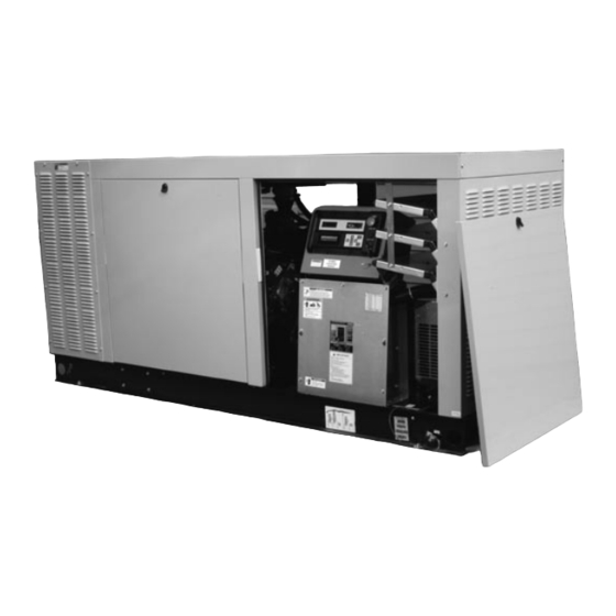
- Page 1 InstallatIon GuIdelInes Siemens Liquid-cooled Generators www.sea.siemens.com/generators • 800-844-0029...
- Page 2 This booklet is designed to familiarize you with the installation process for Siemens’ liquid-cooled residential and commercial generators. This booklet does not replace or supersede any information contained in any of the written documents shipped with your equipment. This booklet should only be used in conjunction with the Owner’s Manual, Installation Manual and...
-
Page 3: General Hazards
GENERAL HAZARDS • For safety reasons, it is recommended that the equipment be installed, serviced and repaired by an Authorized Service Dealer or other competent, qualified electrician or installation technician who is familiar with applicable codes, standards and regulations. The operator must also comply with all such codes, standards and regulations. -
Page 4: Electrical Hazards
ELECTRICAL HAZARDS • All generators covered by this guide produce dangerous electrical voltages and can cause fatal electrical shock. Utility power delivers extremely high and dangerous voltages to the transfer switch as well as the standby generator. Avoid contact with bare wires, terminals, connections, etc., on the generator as well as the transfer switch, if applicable. -
Page 5: Fire Hazards
• Never wear jewelry when working on this equipment. Jewelry can conduct electricity resulting in electric shock, or may get caught in moving components causing injury. FIRE HAZARDS • Keep a fire extinguisher near the generator at all times. Do NOT use any carbon tetra-chloride type extinguisher. -
Page 6: Nfpa Standards
Only qualified, competent installation contractors or electricians thoroughly familiar with applicable codes, standards and regulations should install these standby electric power systems. Installers must comply strictly with all codes, standards and regulations pertaining to the installation. After the system has been installed, do nothing that might render the installation in non-compliance with such codes, standards and regulation NFPA STANDARDS The following published standards booklets pertaining to standby electric... -
Page 7: Grounding The Generator
• A52.1, AMERICAN NATIONAL STANDARD FOR CHIMNEYS, FIREPLACES AND VENTING SYSTEMS, available from the American National Standard Institute, 1430 Broadway, New York, NY 10018. The installer must comply with all applicable state and local codes. GROUNDING THE GENERATOR A grounding lug is provided on the generator mounting base for the purpose of grounding the frame and the external electrically conductive parts of this equipment to an approved earth ground and/or grounding rods where required by the National Electrical Code (Figure 1.6). -
Page 8: Vented Batteries
VENTED BATTERIES The electrolyte is a diluted sulfuric acid that is harmful to the skin and eyes. It is electrically conductive and corrosive. The following procedures are to be observed: • Wear full eye protection and protective clothing. • If electrolyte contacts the skin, wash it off immediately with water. •... -
Page 9: Before You Begin
BEFORE YOU BEGIN Contact the local inspector or City Hall to make sure you are aware of all federal, state and local codes that could impact the installation. Secure all required permits before starting the job. MOUNTING PAD The mounting pad should be located as close as possible to the transfer switch and fuel supply. -
Page 10: Generator Placement
GENERATOR PLACEMENT Use a forklift, boom truck or similar equipment with sufficient capacity to move the generator to the mounting pad area. The operator should be certified and experienced in generator installation. Before placing the generator on the pad, inspect for shipping damage and if necessary, file a claim with the shipper. - Page 11 CONNECTING THE FUEL SYSTEM Gaseous fuel systems should be installed by a licensed plumber who is experienced in generator installation and is familiar with local codes and regulations. When installing rigid natural gas lines, always use AGA approved black pipe. In most applications, a manual shutoff valve and a primary regulator must be a part of the installation.
- Page 12 AUTOMATIC TRANSFER SwITCH INSTALLATION Always inspect the transfer switch for shipping damage. Never mount a switch that shows any evidence of damage. Locate the transfer switch as close as possible to the main service and load distribution panel. Make sure the switch is not located where water or corrosive substances could drip onto the enclosure.
- Page 13 Total Isolation The generator will be backing up all electrical loads within the circuit, so the amperage rating of the transfer switch must be equal to, or greater than, the amperage rating of the normal utility service. Unless a service entrance rated transfer switch is used, a main service disconnect (D) must be located before the transfer switch.
- Page 14 HTS Transfer Switches – Equivalent to X-type HTS switches are used on generators equipped with the PowerManager H-100 ® Controller. Power wiring lugs are clearly marked in the transfer switch. N = Normal Utility Supply E = Generator Connection Panel T = Load Distribution Panel Neutral wires from the utility, the load source and the generator are all connected to the same lug in the switch.
- Page 15 BATTERY INSTALLATION Before connecting the battery, make certain that normal utility voltage at the transfer switch is correct and the system is ready to be put into operation. Check the engine oil, the coolant level, belt tension, and if so equipped, the gearbox oil.
-
Page 16: General Instructions
You’ll need to check the control panel to make sure the H-100 controller is properly configured for the HTS transfer switch. Using the control panel is simple once you understand the process. If the main menu screen is not showing on the right screen display, press the MENU button. -
Page 17: Navigation Tips
NAVIGATION TIPS Use the ARROW keys to move the cursor up, down, left or right. When the cursor is flashing, it can be moved to another line or location on the screen, but no settings can be changed. In order to change a setting, you will always have to press ENTER. -
Page 18: Operational Checks
Press ENTER. When the cursor becomes a static underline, press either the UP OR DOWN arrow key once and the screen should show “HTS #1 Enabled”. Press ENTER to save the setting. To confirm that the controller is communicating properly with the HTS transfer switch, use the ARROW keys to scroll to the bottom of the screen and select the “go back”... - Page 19 Verify that utility voltage and frequency are correct in the transfer switch. In 3- phase applications, you will also need to verify phase rotation. If phase rotation is incorrect, switch the A and C connections in the generator connection box and check phase rotation again.
- Page 20 Place the transfer switch in AUTO and open the main breaker. The generator should start and after the appropriate time delay, the transfer switch should transfer power to the generator without any loads. Close the individual breakers in the distribution panel one at a time until the generator has accepted the entire load.
-
Page 21: Setting The Time And Date
SETTING THE TIME & DATE From the main menu, use the DOWN arrow key to move the flashing cursor to “Status” and press ENTER to go to page (1- 2). Use the ARROW keys to move the flashing cursor to the beginning of the time / date line and press ENTER. - Page 22 ENABLING & SCHEDULING THE wEEkLY EXERCISE FUNCTION From the main menu , select “Exercise/HTS” and press ENTER once to go to page 1 of the section. If the top line of the display shows “Y Exercise Enabled”, the setting is correct. If the top line of the display shows “N Exercise Enabled”, you will have to enable the exercise function.
- Page 23 Use either the UP or DOWN arrow key to change the “N” to “Y” and press ENTER to save the setting. When finished, press MENU to return to the main menu display. Finally, make sure that both the generator and the transfer switch are in the AUTO position before leaving the job site.
- Page 24 P .O. Box 8 • Waukesha, WI 53187 Phone: 800-844-0029 Fax: 800-844-0459 www.sea.siemens.com/generators...