Table of Contents
Advertisement
Quick Links
Advertisement
Table of Contents

Related Manuals for Volvo Penta MD22


Summary of Contents for Volvo Penta MD22
- Page 1 Workshop Manual Engine repair 2(0) MD22, TMD22, TAMD22...
-
Page 3: Table Of Contents
Engine repair Marine Engines MD22 • TMD22 • TAMD22 Contents General Information Crankshaft assembly Safety Information ..........3 General ..............43 General Information .......... 6 Repair Instructions Repair instructions ..........7 Crankshaft pulley, replacement (14A-01) .... 44 Special tools ............10 Front sealing ring, replacement (14A-02) .... - Page 4 Engine settings Flywheel, flywheel cover General ..............71 General ............... 112 Repair Instructions Repair Instructions Setting the 1 piston at top dead center of Flywheel, replacement (21A-01) ......112 compression stroke (17A-01) ......72 Ring gear, replacement (21A-02) ....... 112 Valve timings, checking and adjustment Flywheel cover, replacement (21A-03) ....
-
Page 5: Safety Information
Introduction This Workshop Manual contains descriptions and turned off immediately prior to starting work repair instructions for Volvo Penta products or prod- on it. Reinstall all protective parts removed during service operations before starting the uct versions contained in the contents list. Ensure engine. - Page 6 General instructions Always use protective goggles where there is Store oil and fuel-soaked rags and fuel and oil a danger of pieces of metal, sparks from filters safely. In certain conditions, oil-soaked grinding, acid or other chemicals being thrown rags can spontaneously ignite. Replaced fuel into your eyes.
- Page 7 (gasoline engines) and fuel system on Use an adjustable lifting beam or lifting beam Volvo Penta products are designed and con- specifically for the engine to raise the engine structed to minimize the risk of fire and explo- to ensure safe handling and to avoid damaging sion.
-
Page 8: General Information
This Workshop Manual has been developed primari- proved by Volvo Penta. ly for Volvo Penta service workshops and qualified personnel. Personnel using this book are assumed • No modifications to the exhaust pipes and air... -
Page 9: Repair Instructions
Take special care when working on-board, that oil All procedures for which there are Volvo Penta spe- and waste is taken for destruction and is not acci- cial tools in this Workshop Manual are carried out dentally pumped into the environment with bilge wa- using these. - Page 10 In this Volvo Penta Service Manual the user will find ommended angle is added according to the protrac- that each section where these agents are applied in tor scale.
- Page 11 General instructions • Always used chloroprene rubber gloves (gloves Safety precautions for Fluorine for handling chemicals) and protective goggles. rubber • Treat removed seals in the same way as corro- sive acid. All remains, even the ash can be ex- Fluorine rubber is a common material in sealing tremely corrosive.
-
Page 12: Special Tools
Special tools Special tools In all cases where it is practical the tool number, except for the final digit, has been stamped on the tool, The final digit (after the hyphen) is a control number. 884 955 8858 018 885 019 885 021 885 020 885 022... - Page 13 Special tools 885 032 885 033 885 034 885 035 885 036 885 037 885 038 885 041 885 139 885032-3 Protective socket for front stuffing box, 885036-4 Belt tension gauge for timing belt. crankshaft. 885037-2 Adjustment drifts for the camshaft and 885033-1 Installation tool for front stuffing box, crankshaft.
-
Page 14: Identification Numbers
General information Identifying numbers Your engine and transmission has identification plates with identification numbers. This information should al- ways be quoted when ordering replacement parts. The appearance and location of identification plates is shown below. The figures in brackets refer to the location of the identification numbers on the identification plate. -
Page 15: Introduction To The Engine
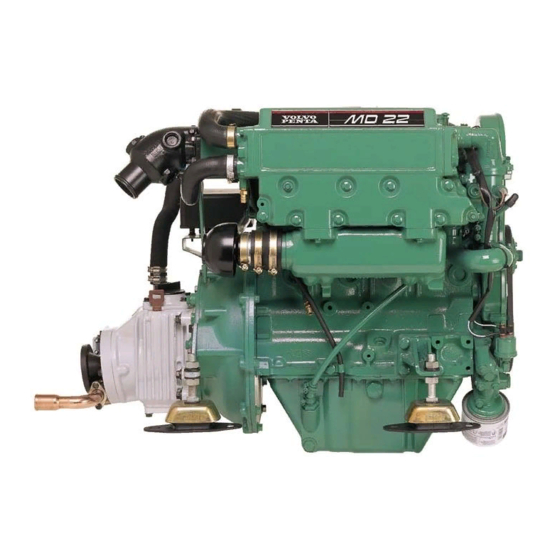
General information Engine presentation 1. Coolant filler 2. Heat exchanger 3. Pipe for oil scavenging pump 4. Oil filter 5. Starter motor 6. Generator 7. Injection pump 8. Fuel feed pump 9. Dipstick (engine) 10. Oil filler cap (engine) 11. Fuel filter 12. - Page 16 General information 12 13 14 15 18, 19 MD22P/MS25 12 13 14 15 TMD22/MS2 12 13 14 15 18, 19 TMD22P/HS25...
- Page 17 General information 12 13 14 15 TAMD22P/SX 1. Turbo (TMD, TAMD) 2. Coolant filler 3. Heat exchanger 4. Oil cooler 5. Pipe for oil scavenging pump 6. Charge air cooler (CAC) (TAMD) 7. Oil filter 8. Starter motor 9. Generator 10.
-
Page 18: Cylinder Head
Cylinder head Cylinder head General The carbon deposits in a diesel engine are small the valve lifters and the top of the valves so that ad- and therefore the number of operational hours do justment is possible. not give an indication of when it is time to recondi- The cylinder head has two valves per cylinder. -
Page 19: Repair Instructions
Cylinder head Repair Instructions Remove the engine lifting brackets. If nothing is Camshaft cover, replacement driven from the rear end of the camshaft, remove (12A-01) the rear cover and install the camshaft lock 885025 (B1). This ensures that the camshaft does not tilt Special tools: 885025 when the camshaft cover is removed. -
Page 20: Valve Clearance, Check (12A-02)
Cylinder head Valve clearance, check (12A-02) Special tools: 885025, 885024 Check that the groove in the camshaft cover and the mating surfaces on the cylinder head and cover are clean. Apply a 2mm bead of silicon in the outer groove of the cover, but leave the inner groove empty as illustrated in illustration (C). -
Page 21: Valve Clearance, Adjustment (12A-03)
Cylinder head Install the camshaft mountings 885024 (A1) to hold Valve clearance, adjustment the camshaft and mount the mountings with the rel- (12A–03) evant mounting screws for the cover. It is vital to move the rear camshaft stuffing box on the cam- Special tools: 885024, 885025, 885037 shaft to secure sufficient clearance between the rear mounting and the stuffing box. - Page 22 Cylinder head Install the new front and rear stuffing box on the camshaft, operations 12A-04 and 12A-05. Install the camshaft pulley and the timing belt, see section 15. Remove the locking drifts from the fuel injection pump pulley and adjust the belt tension, operation 15A-03.
-
Page 23: Front Sealing Ring, Replacement (12A-04)
Cylinder head Front sealing ring, replacement (12A-04) Special tools: 885026, 885018, 885037 Disconnect the battery Remove the screw from the adjustment hole on the top of the front end of the camshaft cover (12A.03/ A4). Turn the crankshaft until the adjustment hole in the front of the camshaft front bearing journal corre- sponds with the hole in the cover. -
Page 24: Rear Sealing Ring, Replacement (12A-05)
Cylinder head Rear sealing ring, replacement (12A-05) Special tools: 885019, 885020, 885038 Remove the seawater pump and the drive housing and remove the drive adapter from the camshaft end, see section 20. Ensure that the stuffing box and the camshaft are clean and undamaged. -
Page 25: Camshaft, Replacement (12A-06)
Cylinder head Camshaft, replacement Check the camshaft for wear and damage and re- (12A-06) place it if required. Special tools: 885037 Ensure that the camshaft is clean and lubricated Disconnect the battery with fresh engine oil. Install the camshaft in position and check the valve clearance if necessary, see operation 12A-02. -
Page 26: Cylinder Head Assembly, Replacement (12A-07)
Cylinder head Cylinder head assembly, Check the fuel injection pump adjustment, opera- replacement (12A-07) tions 17A-03. Special tools: 885037 Install the cap of the timing cover, operation 15A- Disconnect the battery. 01. Install the screw in the adjustment hole on top of the camshaft cover front section. - Page 27 Cylinder head Remove the injectors, operation 19A-02 and the glow plugs, operation 22C-01 to prevent any possi- ble damage to the tips. Remove the screw from the adjustment hole on the top of the front end of the camshaft cover 12A.03/ A4.
- Page 28 Cylinder head If no tool is available make a suitable marking on each screw flange (C1). Make other markings on Ensure that the two guide sleeves (12A.08/B1) is in the cylinder head (C2) with 90° clockwise offset in position in the cylinder block surface and install the relation to the markings on the screws.
- Page 29 Cylinder head Check the fuel injection pump adjustment, opera- Fill the engine coolant system. See operation 20A- tions 17A-03 and remove the adjustment drifts. Turn the crankshaft two revolutions to ensure that there is nothing preventing free movement. Connect the battery. Install the glow plugs, operation 22C-01.
-
Page 30: Valves And Valve Springs, Replacement (12A-08)
Cylinder head Press the valve springs together with the valve Valves and valve springs, spring tensioners (A1). Ensure that the spring is replacement (12A-08) pressed straight downwards so that the valve stem is not damaged. Remove the valve cotter (B1). Special tools: 885023 Remove the cylinder head, operations 12A-07. -
Page 31: Valves And Valve Springs, Inspection (12A-09)
Cylinder head Valves and valve springs, Use the valve spring tensioner to compress the inspection (12A-09) valve spring and the install the valve cotter (B1). Ensure that the valve spring is pressed straight down so that the valve stem is not damaged. Lubricate the shims and valve lifters. -
Page 32: Valve Guides, Inspection (12A-10)
Cylinder head Valve guides, inspection (12A-10) Special tools: 885021, 885022 Check the valve guides for wear. The maximum play between the valve stem and the hole in the guide is 0.13 mm. If the clearance is greater when a new valve is installed, a new valve guide must be installed. -
Page 33: Cylinder Head, Inspection (12A-12)
Cylinder head Cylinder head, inspection (12A-12) Remove the cylinder head assembly, operations 12A-07. Remove the thermostat housing. Remove the seawater pump, operation 20A-06. Use a straight edged ruler and a feeler gauge to Remove the camshaft cover, operation 12A-01 and check the latitudinal, longitudinal and diagonal flat- the camshaft. -
Page 34: Valve Seats, Grinding (12A-13)
Cylinder head Valve seat, grinding (12A-13) Valve seats with more serious damage can be cor- rected using a milling tool, operation 12A-13 or a new valve seats can be installed, operation 12A-14. If the valve guide is worn it should be replaced, op- eration 12A-11. -
Page 35: Valve Seats, Replacement (12A-14)
Cylinder head Valve seat, replacement (12A-14) Install a new valve guide, operation 12A-11. Work a small segment from the inside of one side of the valve seat to a depth of 8.25 mm from the sur- face of the cylinder head. Split the seat at the thin- nest point and remove it from the cylinder block. -
Page 36: Piston And Connecting Rod Assembly
Piston and connecting rod General The combustion chamber on the upper side of the piston has a special ”swirl lip” to provide an effec- tive fuel – air mixture. On the high effects the upper side of the piston is turned to ensure clearance be- tween the valves and the glow plugs. -
Page 37: Repair Instructions
Repair Instructions Big ends, replacement (13A-01) Drain engine oil. Remove the oil pan, operation 18A-03 Remove the oil screen and extractor pipe, operation 18A-04. Turn the crankshaft until the relevant connecting rod is in its lowest position. Unscrew the nuts and remove the bearing cap. Remove the lower bearing shell from the bearing cap and put it together with the cap. -
Page 38: Big Ends, Inspection (13A-02)
Piston and connecting rod Piston and connecting rod as- Clean, lubricate and install the lower bearing shell in sembly, replacement (13A-03) the cap. Ensure that the guide lug is slid well into the cut out (A2). Remove the protective hosing from the connecting rod screws and check that the Drain the engine oil and the engine coolant system. - Page 39 Piston and connecting rod Remove the big end bearing cap and the connecting Ensure that the piston, cylinder bore, big end jour- rod bearing caps, operation 13A-01. Keep the bear- nal and connecting rod big end are clean. Lubricate ing shells with the relevant caps so that they can be the piston and cylinder bore with fresh engine oil.
- Page 40 Piston and connecting rod Slide the piston and connecting rod through the cyl- Install the oil screen and extractor pipe if required, inder bore and down to the big end journal. Turn the operation 18A-04. connecting rod so that the arrow on the upper side of the piston points towards the front end of the en- gine.
-
Page 41: Piston Rings, Replacement (13A-04)
Install the piston rings with an appropriate piston ring pliers Separate the ring gap just sufficiently that the ring ends do not damage the piston. MD22L, MD22, TMD22 Insert the expander ring for the oil scraper ring in TMD22P, TAMD22 the lower piston ring groove with the catch through both end of the rings (A). -
Page 42: Piston And Connecting Rod, Assembly / Dismantling (13A-05)
Piston and connecting rod Piston and connecting rod, assembly / dismantling (13A-05) Remove the piston rings, operation 13A-04. Remove the snap rings holding the piston pins in position. Make a temporary marking on the piston to display the cylinder number as given on the connecting rod. If the original piston is used, ensure that it is in- Make the marking on the piston on the same side stalled on the correct connecting rod and the origi-... -
Page 43: Piston And Piston Rings, Inspection (13A-06)
Piston and connecting rod Remove the piston rings, operation 13A-04. Clean the piston ring and the piston ring grooves. Place the connecting rod with piston upside down. The locating lug (B2) on the connecting rod must be on the same side as the arrow (B1) on the under- side of the piston. -
Page 44: Connecting Rod, Inspection (13A-07)
Piston and connecting rod Connecting rod, inspection Connecting rod bushing, (13A-07) replacement (13A-08) Check the connecting rods for deformation, see Workshop Manual “Technical Data”. Press out the old bushing with an appropriate drift. Check the connecting rod bushing for wear or other Clean the bearing recess in the connecting rod and damage and replace it as necessary. -
Page 45: Crankshaft Assembly
Crankshaft assembly General the rear stuffing box is located directly in the fly- The crankshaft is made of ductile cast iron. It has wheel cover or the back plate. integral balancing weights and five main bearing journals. The crankshaft front end has two separate key- The axial play is controlled by two sectioned thrust grooves. -
Page 46: Repair Instructions
Repair Instructions Slacken off the pulley center screw and remove the Crankshaft pulley, replacement pulley (C). Use a large screwdriver or similar tool (14A-01) as a counterhold at the flywheel ring gear. NOTE! The belt pulley is locked to the front end of the crankshaft using Loctite 648 and can only be re- Disconnect the battery. -
Page 47: Front Sealing Ring, Replacement (14A-02)
Crankshaft assembly Front sealing ring, replacement (14A-02) Special tools: 885031, 885032, 885033, 885037 Disconnect the battery Remove the screw from the adjustment hole on the top of the front end of the camshaft cover (12A.03/ A4). Turn the crankshaft until the adjustment hole in the front of the camshaft front bearing journal corre- sponds with the hole in the cover. - Page 48 Crankshaft assembly Remove the adjustment drifts and the pulley drifts. Check the fuel injection pump adjustment, opera- tions 17A-03. Turn the crankshaft two revolutions to ensure that there is nothing preventing free movement. Install the cap for the timing cover, operation 15A- 01.
-
Page 49: Rear Sealing Ring, Replacement (14A-03)
Crankshaft assembly Rear sealing ring, replacement Clean the sealing ring housing and the flange on the (14A-03) crankshaft. Special tools: 885030, 885034, 885035 Lightly the sealing ring housing, the flange on the Disconnect the battery crankshaft and the sealing ring seal lip with fresh engine oil. -
Page 50: Crankshaft Axial Clearance, Checking (14A-04)
Crankshaft assembly Locate the ring (C1) from tool 885035 on the crank- Crankshaft axial clearance, shaft flange with the correct side of the ring towards checking (14A-04) the sealing ring. If the sealing ring is to be installed in the front position (see paragraph 4), install the socket with the end with diameter markings turned to the sealing ring. - Page 51 Crankshaft assembly Check that the guide sleeves are correctly installed in the bearing cap or in the cylinder block. Check that the bearing shell is correctly installed in the cap and that the main bearing journals are clean. Lubricate the bearing shell with fresh engine oil.
-
Page 52: Main Bearings, Replacement (14A-06)
Crankshaft assembly Clean the upper bearing shell and lubricate the Main bearings, replacement bearing surface with fresh engine oil. (14A-06) NOTE! There is only a lubrication hole in the upper bearing shell and it must therefore be placed (with crankshaft installed) against the cylinder block. -
Page 53: Main Bearings, Inspection (14A-07)
Crankshaft assembly Crankshaft, replacement Check the mounting screws for wear and deforma- (14A-08) tion and replace them if required. Lightly lubricate the threads with engine oil. Install the screws and washers and tighten the screws in stages and even- Drain the engine oil and the engine coolant system. ly to 112 Nm. - Page 54 Crankshaft assembly Check that all the big end caps are marked with the Clean the main bearing housing and the bearing number of the relevant cylinder. Remove the caps shells. Install the bearing shells with the lugs well and the lower big end shells, operation 13A-01. into the cut outs.
-
Page 55: Crankshaft, Inspection (14A-09)
Crankshaft assembly Check the axial clearance of the crankshaft and re- Install the timing cover and the timing pulleys, see place the thrust washer if necessary. section 15. Install the timing belt, operation 15A-04, with the temporary markings on the belt aligned to the marked teeth on the pulleys. -
Page 56: Timing Cover And Sprocket
Timing cover and sprocket General The drive pulleys are installed on the camshaft (A1) and the fuel injection pump (A2). These pulleys are driven by a toothed belt (A3) from one toothed pul- ley mounted on the crankshaft (A4). The pulleys are made of sintered iron with 2% copper and the belt is made of neoprene and glass fibre. -
Page 57: Repair Instructions
Repair Instructions Timing cover outer, replacement (15A-01) Check that the cap is clean and that all the spring clips are fastened at the timing cover. Disconnect the battery. Install the cap on the timing cover and ensure that all the clips are in position. Remove the generator (GEN) drive belt, operation 22A-03. -
Page 58: Timing Belt, Inspection (15A-02)
Timing cover and drive Timing belt, inspection (15A-02) Special tools: 885036 Press the ball end of the belt tension gauge and in- stall the gauge over the belt. Ensure that the gauge foot is located under the belt and between two teeth (B). -
Page 59: Timing Belt, Tension (15A-03)
Timing cover and drive Unscrew the domed screws holding the belt ten- Timing belt, tension (15A-03) sioner roller. Adjust the belt tension using a hexago- nal key in the hexagonal socket in the roller (C). Special tools: 885036, 885037 The correct tension for a new belt is 425-465 N and for a used belt 340-370 N. -
Page 60: Timing Belt, Replacement (15A-04)
Timing cover and drive Timing belt, replacement Check the belt teeth for wear. Check the belt for oil (15A-04) contamination, cracks and other damage. Replace the belt if any fault is found. Special tools: 885037 Install the timing belt over the crankshaft, camshaft Disconnect the battery. -
Page 61: Fuel Injection Pump Pulley, Replacement (15A-05)
Timing cover and drive Fuel injection pump pulley, Install the cap of the timing cover, operation 15A-01 replacement (15A-05) and install the inspection hatch. Special tools: 885037, 885027, 885029 Install the mounting screw in the adjustment hole in the camshaft cover. Disconnect the battery. - Page 62 There the camshaft cover. are two keygrooves and two marked teeth, “A” and “B”, on the pulley. On engines types MD22 and MD22L use the keygroove lying on the same side as the tooth marked “A”. On engines types TMD22 Connect the battery.
-
Page 63: Camshaft Pulley, Replacement (15A-06)
Timing cover and drive Camshaft pulley, replacement (15A-06) Special tools: 885027, 885029, 885037 Disconnect the battery. Remove the screw over the adjustment hole in the camshaft cover. Turn the crankshaft until the ad- justment hole in the front of the camshaft corre- sponds with the hole in the cover. -
Page 64: Crankshaft Pulley, Replacement (15A-07)
Timing cover and drive Crankshaft pulley, replacement Turn the crankshaft two revolutions to ensure that (15A-07) there is nothing preventing free movement Special tools: 885029, 885027, 885037 Install the cap of the timing cover, operation 15A-01 Disconnect the battery. and install the inspection hatch. Remove the screw over the adjustment hole in the Install the mounting screw in the adjustment hole in camshaft cover. - Page 65 Timing cover and drive Insert the thin end spacer piece in the crankshaft (A1). Install the main tool 885027 (B) on the pulley using the mounting screws and tighten the center Apply a bead of Loctite 648 (A3) in a complete cir- screws against the spacer piece to remove the pul- cle internally in the hole in the pulley (A4), 6.5 mm ley.
- Page 66 Timing cover and drive Slide the (A8) into the keygroove to a depth of 5 mm Install the screw in the adjustment hole in the cam- measured from the pulley front end plate. shaft cover. NOTE! It is important that all excess Loctite is wiped off from the front end of the crankshaft and from the pulley before the pulley is installed.
-
Page 67: Timing Cover Inner, Replacement (15A-08)
Timing cover and drive Timing cover inner, replace- ment (15A-08) Special tools: 885037, 885027, 885029 Disconnect the battery. Remove the screw over the adjustment hole in the camshaft cover. Turn the crankshaft until the ad- justment hole in the front of the camshaft corre- sponds with the hole in the cover. - Page 68 Timing cover and drive Remove the fuel injection pump pulley, operation 15A-05 and the camshaft pulley, operation 15A-06. Install the crankshaft pulley if required, operation 14A-01A. Install the timing belt, operation 15A-04. Remove the fixing pin for the fuel injection pump pulley and adjust the belt tension, operation 15A-03.
-
Page 69: Cylinder Block
Cylinder block General The cylinder block is made of cast iron with sides which extend below the crankshaft for maximum support. The cylinder bore is machined directly into the block and is specially honed to minimize wear and oil consumption. Repair instructions Cylinder block, replacement (16A.01) - Page 70 Cylinder block Remove the cylinder head assembly, operations 12A-07. Remove the oil pump, operation 20A-11. Remove the oil filter/ separator unit. Remove the oil pan, operation 18A-03. Install the fuel injection pump bracket. Check that the guide pins (A1) is correctly installed. Tighten the mounting screws to 43 Nm.
-
Page 71: Cylinder Block, Inspection (16A-02)
Cylinder block Cylinder block, inspection Install the cylinder head assembly, operation 12A- (16A-02) Clean the coolant and lubrication channels. Install the fuel filter, injectors and fuel injection pump, see section 19. Check the cylinder block for cracks and other dam- age. -
Page 72: Cylinder Bore, Honing (16A-03)
Cylinder block If the cylinder bores are damaged or worn more than 0.15 mm, measured in the diameter, the bore A new Flex-Hone must be used on an old cylinder can be bored out and honed to 0.50 mm, diametri- bore first in order to remove any loose material and cally oversize, and oversized pistons can be in- sharp edges. -
Page 73: Engine Settings
Engine settings General The installation holes for the adjustment drifts are in marks (A and B) and two keygrooves. The key- the flywheel and in the front camshaft bearing jour- groove on the same side as the relevant adjustment nal. When these holes are aligned to the adjustment mark must always be used. -
Page 74: Repair Instructions
Repair Instructions Setting the 1 piston at top Valve timings, checking/ dead center of the compres- adjustment (17A-02) sion stroke (17A-01) Special tools: 885037 Special tools: 885037 Position the piston in cylinder 1 at TDC in the com- pression stroke, operation 17A-01 If both the adjust- ment drifts can be installed, the valve timing is cor- Disconnect the battery and remove the screw over rect. -
Page 75: Injection Timing, Checking / Adjusting
Engine settings Injection timing, checking/ad- Check the fuel injection pump adjustment, opera- justment (17A-03) tions 17A-03. Special tools: 884955, 885139 (TMD22P, TAMD22), 885037 Remove the adjustment drifts and turn the engine two revolutions to ensure that there is nothing pre- venting free movement. - Page 76 Engine settings If the read out is not within 0.05 mm of the correct setting, disconnect the fuel delivery lines from the pump. Use a wrench to prevent the output terminals on the fuel pump (FP) from moving when the deliv- ery lines are removed or installed.
-
Page 77: Lubrication System
Lubrication system General The oil pump is located around the front end of the From the pump the oil passes through a filter crankshaft, the pumps inner rotor is driven by a key mounted on the pump housing. After the filter the oil in the crankshaft. -
Page 78: Repair Instructions
Lubrication system Repair Instructions Oil filter, replacement (18A-01) Check that there is lubricating oil in the oil pan. Place a container under the filter to collect any Start the engine and check the filter for leaks. spilled fluid. Check the oil level on the dipstick when the engine has cooled and top up the oil in the oil pan if neces- sary. -
Page 79: Oil Pan, Replacement (18A-03)
Lubrication system Oil pan, replacement (18A-03) Drain the oil. Remove the dip stick. Disconnect the crankcase ventilation return pipe. Arrange a support for the oil pan if required. Re- move the screws holding the oil pan against the cyl- inder block. Lower the oil pan and remove the gas- ket. -
Page 80: Oil Screen And Suction Pipe, Replacement (18A-04)
Lubrication system Oil screen and suction pipe, Oil screen and suction pipe, replacement inspection (18A-05) (18A-04) The oil screen is an integrated part of the suction pipe. No regular service is required, but clean the Clean the unit in kerosene and dry it carefully. oil screen when it is dismantled. -
Page 81: Oil Pump, Replacement (18A-06)
Lubrication system Oil pump, replacement (18A-06) Special tools: 885032, 885037 Disconnect the battery Remove the screw from the adjustment hole on the top of the front end of the camshaft cover. Turn the crankshaft until the adjustment hole in the front of the camshaft front bearing journal corresponds with the hole in the cover. - Page 82 Lubrication system Install the front stuffing box in the pump if neces- sary, see operation 14A-02. Install a new front key on the crankshaft. Install the timing cover, operation 15A-08. Remove the pulleys and timing belt, see section 15. Check the fuel injection pump adjustment, opera- tions 17A-03.
-
Page 83: Oil Pump, Inspection (18A-07)
Lubrication system Oil pump, inspection (18A-07) Check the rotor axial clearance using a ruler and a If the rotors are so damaged that it affects the oil feeler gauge (C). For size and all clearances, see pump capacity, the whole oil pump must be re- Workshop Manual “Technical Data”. -
Page 84: Relief Valve, Replacement (18A-08)
Lubrication system Relief valve, replacement Install the piston in the sleeve with the open end of (18A-08) the piston turned inwards. Install the spring over the lug on the end of the piston. Install the end plug with The relief valve is installed on the left side of the the sprung end inserted in the cutout in the plug. -
Page 85: Fuel System
Fuel system General The supply pump is the membrane type and is me- All engines are equipped with Bosch fuel injection pump. These pumps have mechanical engine speed chanically driven. It is mounted on the right side of regulator. the camshaft cover and is driven by an eccentric cam on the camshaft. -
Page 86: Repair Instructions
Bleed the air from the fuel filter, see operation 19A- NOTE! It is extremely important that only original Volvo Penta filter holders are used. Using the wrong type of holder can damage the fuel injection pump. -
Page 87: Injectors, Fault-Tracing
Fuel injection system Injectors, fault-tracing Check the holder unit for wear and deformation and A faulty injector can cause engine misfires. replace the unit if required. Replace the injector seat gasket. To find the faulty injector, run the engine at high idling speed. -
Page 88: Feed Pump, Replacement (19A-03)
Fuel injection system Feed pump, replacement Slacken off the bleed screw in the fuel filter head. (19A-03) Hand pump with the lever on the supply pump to eliminate any air between the supply ball and the fuel filter. Pump with the lever until air free fuel comes out of the bleed screw. -
Page 89: Feed Pump, Reconditioning (19A-04)
Fuel injection system Feed pump, reconditioning The valves (B4) are jammed in the housing and can (19A-04) be removed with a suitable jimmy tool. Part of the flattened metal must be removed before the valves can be removed. Clean the outside of the supply pump. Disconnecting the control arm: secure the rocker (B12) with a vise and hit the pump housing with a soft faced hammer to release the two holders (B11). -
Page 90: Fuel Supply Pressure, Checking (19A-05)
Fuel injection system Fuel supply pressure, Install the diaphragm in position above the bottom checking (19A-05) pump half with the connecting arm fin upwards to- wards the slit in the control arm. Ensure that the If there is fuel leakage through the hole in the pump small bulge in the edge of the diaphragm (19A.04/ housing (19A.04/C3), it means that the diaphragm is C1) is at a 90°... -
Page 91: Fuel Injection Pump, Replacement (19A-06)
Fuel injection system Fuel injection pump, replace- ment (19A-06) Special tools: 885027, 885029, 885037 Disconnect the battery. Position the piston in cylinder 1 at TDC in the com- pression stroke, operation 17A-01 and install the adjustment drifts 885037. Remove the locknuts and remove the pump (B) – Remove the cap for the timing cover, the timing belt ensure that the key does not fall out of the drive and the fuel injection pump pulley, see section 15. - Page 92 Fuel injection system Check that the key is correctly installed on the Check that the adjustment drifts are removed. pump shaft. Install the fuel injection pump in posi- tion with the locknuts sufficiently tightened to hold the pump secure, but not so much that it prevents radial movement in the housing.
-
Page 93: Idling Speed, Adjustment (19A-07)
Fuel injection system Idling speed, adjustment Run the engine and check for any leakage. Check (19A-07) that the idle speed is correct, operation 19A-07. If a new fuel injection pump has been installed, check that maximum idling speed, operation 19A- Run the engine to operating temperature and check the idling speed. -
Page 94: Fuel Injection System, Bleeding (19A-08)
Fuel injection system Fuel injection system, bleeding (19A-08) If air has entered the fuel injection system it must be removed before the engine is started. Air can enter the fuel injection system if: • The fuel tank is run dry during normal opera- tion. -
Page 95: Cooling System
Cooling system General When the coolant temperature increases, the ther- The engine has two cooling circuits. The closed cir- mostat valve opens, the by-pass connection closes cuit is filled with coolant which is used for cooling and the coolant passes through the heat exchanger. the cylinder block and cylinder head. - Page 96 Cooling system MD22L-B, MD22P-B, TMD22-B, TMD22P-C, TAMD22P-B Cylinder block Freshwater pump Thermostat Sea water pump The combined coolant tank, heat exchanger Outlet bend and exhaust manifold Charge air cooler (only TAMD22) Engine oil cooler (MD22P, TMD22, TAMD22)
-
Page 97: Repair Instructions
Cooling system Repair Instructions Coolant, draining (20A-01) Coolant, draining (20A-01) Applies to MD22A, MD22L-A, TMD22A Applies to MD22L-B, MD22P-B, TMD22-B, TMD22P-C, TAMD22P-B WARNING! Do not drain coolant when the en- gine is still warm and the system is pressu- WARNING! Do not drain coolant when the en- rized, as dangerous hot coolant may spray out. -
Page 98: Coolant, Filling (20A-2)
Cooling system Coolant, filling (20A-2) Coolant, filling (20A-2) Applies to MD22A, MD22L-A, TMD22A Applies to MD22L-B, MD22P-B, TMD22-B, TMD22P-C, TAMD22P-B Remove the bleed plug from the hot water connec- Remove the bleed plug from the outlet connection tion (B1) or the plug (B2) on the heat exchanger. for the coolant (B2). -
Page 99: Sea Water Circuit, Draining (20A-03)
Cooling system Sea water circuit, draining Sea water circuit, draining (20A-03) (20A-03) Applies to MD22A, MD22L-A, TMD22A Applies to MD22L-B, MD22P-B, TMD22-B, TMD22P-C, TAMD22P-B Check that the seacock is closed. Check that the seacock is closed. Disconnect both hoses from the sea water pump. Disconnect both hoses from the sea water pump. -
Page 100: Thermostat, Replacement (20A-04)
Cooling system Thermostat, replacement Thermostat, checking (20A-04) Suspend the thermostat in a suitable container filled with water. Drain the cooing system so that the coolant level is below the position of the thermostat and disconnect the upper hose from the coolant outlet connection. Warm the water slowly. -
Page 101: Circulation Pump, Replacement (20A-05)
Cooling system Circulation pump, replacement Check that the mating surfaces of the circulation (20A-05) pump and cylinder block are clean. Disconnect the battery. Drain the coolant circuit, operation 20A-01. Disconnect the suction pipe at the circulation pump and, if necessary, the by-pass connection. Position the piston in cylinder 1 at TDC in the com- pression stroke, operation 17A-01 and install the adjustment drifts. -
Page 102: Sea Water Pump, Replacement (20A-06)
Cooling system Sea water pump, replacement (20A-06) Applies to MD22A, MD22L-A, TMD22A NOTE! If the installation plate and adapter plate for the sea water pump are removed, they must be aligned (using alignment tool 885038) before the pump is installed, see operation 20A-08. Drain the sea water circuit, operation 20A-03. -
Page 103: Sea Water Pump, Reconditioning (20A-07)
Cooling system Sea water pump, replacement Install the pump on the engine with two screws (A1) (20A-06) and (A2) and install the belt. At the correct tension it should be possible to press in the belt approxi- Applies to MD22L-B, MD22P-B, TMD22-B, mately 5 mm between the pulleys. - Page 104 Cooling system Remove the end cover (B13) and the gasket (B14). Press stuffing box (B4) into position in the bearing housing with the lip against the side of the bearing. Lubricate the sealing lip a little. Remove the rubber plug (B12) from the end of the impeller (B11).
- Page 105 Cooling system Sea water pump, recondition- Remove the stuffing box (A7) from the housing. ing (20A-07) Applies to MD22L-B, MD22P-B, TMD22-B, TMD22P-C, TAMD22P-B Check the components for wear or other damage and replace as necessary. Check that all the components are clean. Press the bearing (A9) on the shaft (A11).
-
Page 106: Installation And Adapter Plate For Seawater Pump, Replacement (20A-08)
Cooling system Installation and adapter plate for sea water pump, replace- ment (20A-08) Special tools: 885038 Applies to MD22A, MD22L-A, TMD22A Remove the sea water pump, operation 20A-06 and remove the adapter plate. Disconnect the fuel pipe from the fuel filter and, if necessary, remove the filter. -
Page 107: Oil Cooler, Replacement (20A-09)
Cooling system Oil cooler, replacement If the oil cooler and suspension bracket have been (20A-09) removed: Hold the unit in position and install the two front mounting screws. Install the rear mounting Applies to MD22A, MD22L-A, TMD22A screw through the bracket to the main oil pump and The pipes in the oil cooler do not usually need the spacer sleeve into the cylinder block. - Page 108 Cooling system Oil cooler, replacement (20A-09) Applies to MD22P-B, TMD22-B, TMD22P-C, TAMD22P-B The oil cooler may need cleaning because the cool- ant which passes through it comes from the sea water circuit. Remove the oil pipes / hose from the cooler. Make a mark on the flanges (A1) and the coolant tank, so that the flanges can be reinstalled in the same position.
-
Page 109: Heat Exchanger / Manifold / Coolant Tank, Replacement (20A-10)
Cooling system Heat exchanger / manifold / Remove the gaskets and clean the mating surfaces coolant tank, replacement on the unit, the cylinder head and the coolant pipes. Check the components for signs of damage and re- (20A-10) place if necessary. If the heat exchanger insert needs replacing, see operation 20A-11. - Page 110 Cooling system Heat exchanger / manifold / Connect the sea water intake and outlet pipes to the coolant tank, replacement heat exchanger. The output pipe must be pushed in so that the end of the pipe is in the center of rubber (20A-10) end of the heat exchanger.
-
Page 111: Heat Exchanger, Reconditioning (20A-11)
Cooling system Heat exchanger, reconditioning Place a new manifold gasket in position over the (20A-11) guide pins in the cylinder head (A1). You do not need to use any sealing compound. Check that the Applies to MD22A, MD22L-A, TMD22A gasket is correctly installed. The heat exchanger insert can be removed (with the heat exchanger installed on the engine) if the space behind or in front of the heat exchanger is at least... - Page 112 Cooling system Check the components for signs of damage and re- place if necessary. Slide the sleeve (A1) on the end of the insert until the insert is in contact with the reduced diameter of the sleeve. Press a rubber end (A2) over the other end of the insert until the protrusion inside the rubber end touches the end of the sleeve.
-
Page 113: Charge Air Cooler (Cac), Re- Conditioning (20A-12)
Cooling system Heat exchanger, reconditioning Charge air cooler (CAC), re- (20A-11) conditioning (20A-12) Applies to MD22L-B, MD22P-B, TMD22-B, Applies to TAMD22P-B TMD22P-C, TAMD22P-B Drain the sea water circuit, operation 20A-03. Drain the sea water circuit, operation 20A-03. Remove the cover and press the insert out of the Remove the charge air cooler assembly from the heat exchanger. -
Page 114: Flywheel, Flywheel Cover
Flywheel, flywheel cover General The motor may be equipped with a back plate of The steel flywheel has a hardened ring gear which aluminum or soft carbon steel or a flywheel cover of is installed by the process of shrinking-on. The ring cast iron. - Page 115 Flywheel, flywheel cover Ring gear, replacement (21A-01) WARNING! Protective goggles must be worn for this operation. Check the position of the chamfering on the teeth before removing the ring gear. Removing The ring gear can be removed using a hammer and chisel to break off the collar.
-
Page 116: Flywheel Cover, Replacement (21A-03)
Flywheel, flywheel cover Flywheel cover, replacement (21A-3) Special tools: 885030 Remove the drive components from the rear end of the engine. Remove the starter motor, operation 22B-01. En- gines with reverse gear: Remove the adapter hous- ing for the reverse gear. Apply a continuous 1.5 mm line of sealant on the front surface of the cover, as shown in illustration Remove the flywheel, operation 21A-01. - Page 117 Flywheel, flywheel cover Install the flywheel and the drive adapter for the re- verse gear, operation 21A-01. Check that the guide pins are correctly installed in the housing. Install the adapter housing for the reverse gear and tighten the mounting screws to 43 Nm. Check the concen- tricity of the housing (C) and the axial run-out (D) in the same way as in points 5 and 7 above.
-
Page 118: Electrical System
Electrical system Component description Generator Glow plugs The Valeo A13N 147M generator is driven from the The starting aid for these engines consists of a set crankshaft pulley with a single drive belt. The gen- of glow plugs, one for each cylinder. erator has a capacity of 60 A (early version 50 A). -
Page 119: Repair Instructions
Electrical system Repair Instructions Generator, replacement (22A-01) To prevent damage to the diodes and resistance, the following instructions must be followed. • Do not disconnect the battery when the engine is running. This causes an increase in voltage in the generator charging system, which may cause damage to the diodes or transistors. -
Page 120: Generator, Maintenance
Electrical system Generator, maintenance Connect a good-quality voltmeter with a range of 0- 50 V across the generator and the negative termi- nals. If an ammeter is not connected in the circuit: Con- Check that the drive belt is not worn and that the nect a good-quality ammeter with a range of 0-100 belt tension is correct. -
Page 121: Starter Motor, Replacement (22B-01)
Electrical system Starter motor, replacement Starter motor, maintenance (22B-01) (22B-02) The starter motor must be removed from the en- gine. The brush unit can be removed from the rotor unit Disconnect the battery. the back plate has been removed. Inspect the brushes to ensure that they move freely in their guides and that the cable connectors move Disconnect the starter motor cables. -
Page 122: Starter Motor, Checking (22B-03)
Electrical system Starter motor, checking Glow plugs, replacement (22B-03) (22C-01) Check that the battery is charged. Switch on the lamps and engage the ignition switch. If no lamps are connected to the engine, connect a Disconnect the electrical connections for the glow voltmeter across the battery poles and engage the plugs. -
Page 123: Glow Plugs, Checking Power Supply/Continuity
Electrical system Glow plugs, checking power Glow plugs, function check supply/continuity Disconnect the power supply cable and the cables at the glow plug connectors. Connect a 12 V test lamp between the battery posi- tive pole and ground to check that the lamp oper- ates. -
Page 124: Wiring Diagram
Electrical system Wiring Diagram Instrument panel Cable color Printed circuit board GR =gray Switch for instrument lighting SB =black Tachometer BN =brown Starter button LBN =light brown Button =red Alarm connector PU =purple GN =green W =white BL =blue LBL =light blue OR =orange Unless otherwise stated, cable cross sections = 1.5... - Page 125 Electrical system Instrument panel Voltmeter Button Oil pressure gauge Switch for instrument lighting Engine coolant temperature Tachometer gauge Ignition switch Printed circuit board Alarm...
- Page 126 Electrical system Engine Cable color Engine coolant temperature GR =gray sensor SB =black Coolant temperature switch BN =brown Oil pressure sensor LBN =light brown Pre-heating =red Relay PU =purple Ground fuse GN =green Fuses W =white BL =blue LBL =light blue OR =orange Unless otherwise stated, cable cross sections = 1.5...
-
Page 127: Intake And Exhaust System
Intake and exhaust system Turbocharger, replacement Remove the nuts at the turbocharger flange and re- (only TMD, TAMD) move the turbocharger (TC) (A) and the gasket. Re- move the exhaust elbow and its joint from the turbo- Removing and installing charger (TC) if installed. -
Page 128: Boost Pressure Control Valve, Checking
Intake and exhaust system Boost pressure control valve, Install the exhaust elbow for the turbocharger (TC) checking if required. Check that the mating surfaces on the elbow and the turbocharger (TC) are clean. Install a new gasket. Tighten the nuts to 22 Nm. Connect the oil return line and the boost pressure line to the turbocharger (TC). - Page 129 Notes ....................................................................................................................................................................................................................................................................................................................................................................................................................................................................................................................................................................................................................................................................................................................................................................................................................................................................................................................................................................................................................................................................................................................................................................................................................................................................................................................................................................................
- Page 130 Notes ....................................................................................................................................................................................................................................................................................................................................................................................................................................................................................................................................................................................................................................................................................................................................................................................................................................................................................................................................................................................................................................................................................................................................................................................................................................................................................................................................................................................
- Page 131 We would prefer you to write in English or Swedish. From: ....................................................................Refers to publication: ............................. Publication no.: ..............Issued: ..............Suggestion/reasons: ....................................................................................................................................................................................................................................................................................................................Date: ............Name: ............AB Volvo Penta Customer Support Dept. 42200 SE-405 08 Gothenburg Sweden...