Table of Contents
Advertisement
Advertisement
Table of Contents

Related Manuals for Volvo Penta MD22L


Summary of Contents for Volvo Penta MD22L
- Page 1 INSTRUCTION BOOK MD22L, MD22, TDM22...
-
Page 2: Table Of Contents
Owner’s Manual Marine Diesel Engines MD22L, MD22, TMD22 Contents Safety precautions Maintenance Introduction ..............2 Check daily before starting ........... 20 Check every 14 days ............ 20 Check every 50 hours of operation ......21 General information ............. 4 Check every 200 hours, or least once a year ....22 Running-in .............. -
Page 3: Safety Precautions
Safety precautions Introduction Immobilize the engine by turning off the power supply to the engine at the main switch (break- This Owner’s Manual contains the information you will ers) so it is impossible to start, and lock the need to operate the engine correctly. Check that you switch (breakers) in the OFF position before have the correct Owner’s Manual for your engine. - Page 4 (gasoline/petrol engines) and in can form an explosive gas. This gas is easily the fuel system on Volvo Penta products are ignited and highly volatile. Incorrect connection designed and manufactured to minimize risks of of the battery can cause sparks sufficient to fire and explosion.
-
Page 5: General Information
Volvo Penta a world leader in the marine engine industry. Spare parts As owner of a Volvo Penta marine engine we would also WARNING! The components in the electrical like to welcome you to a worldwide network of dealers... -
Page 6: Warranty
The cost of this work is covered by the Volvo operation, incorrect operation or improper maintenance Penta International Limited Warranty. -
Page 7: Certificated Engines
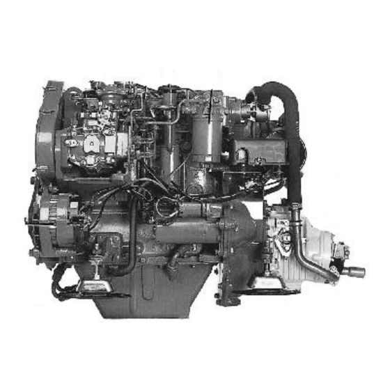
Identifying Numbers must meet the environmental demands set for that engine. In order for Volvo Penta as the manufacturer to Immediately after you have taken delivery of your boat, take responsibility for engines in use, certain require- make a note of the serial number and model designation ments pertaining to service and spare parts must be met. - Page 8 Introduction MD 22L, MD 22, TMD 22 / MS2L, MS2A 1. Fuel liftpump 8. Raw water pump 2. Oil dipstick 9. Filler cap 3. Filler cap for lubricating oil 10. Induction manifold 4. Fuel filter 11. Pipe for oil bilge pump 5.
- Page 9 MD 22L, MD 22, TMD 22 /120S 1. Fuel liftpump 2. Oil dipstick 3. Filler cap for lubricating oil 4. Fuel filter 5. S-drive serial number 6. Zinc anode 7. Alternator 8. Exhaust outlet 9. Raw water pump 10. Filler cap 11.
-
Page 10: Instruments
100 to calculate revolutions per minute. Standard Full throttle: operating range, MD22: 3200–4000r/min. MD22L: 2700–3000 r/min. TMD22 : 4100–4500 r/min. 2. Hour counter Shows the engine operating time in hours and tenth of an hour. 3. Alarm (siren) - Page 11 5. Pressure switch – Alarm test /Acknow- ledge No alarm: Alarm test (all warning lights on – not flashing– and the siren sounding). Alarm: Acknowledgement of alarm.* *The siren stops sounding, but the warning light continues to flash until the fault has been rectified. If a new alarm condition arises, the siren will sound again and the next warning light will also start to flash, and so on.
- Page 12 10. Voltmeter The voltmeter shows the voltage in the starter battery circuit. The voltage should be about 14V during opera- tion. The voltage is about 12V when the engine is off. Supplementary warning display The display has four “windows”. If the acoustic alarm comes on, one of the windows starts to blink (red) to show the cause of the alarm.
-
Page 13: Control
Controls Controls The Volvo Penta single-lever control combines the throttle and gear shift functions in one lever. When starting, for example, the gear change function can easily be switched off so only the engine speed is affected by the lever. When manoeuvring the boat... -
Page 14: Operation
Operation Measures to be taken before starting Open the bottom cock for the cooling water intake. Open the fuel cocks. Check that no leakage of water, fuel or oil occurs. Check the level of coolant. The level should reach filler pipe. WARNING: Closed fresh water system is under pressure. - Page 15 11. Turn the key switch to position “II” (“glow” posi- tion) and hold it there for maximum 7 seconds. Warm engine do not need pre-heating. 12. Turn the key to position “III” to start. Release the key immediately once the engine has started* (it will spring back automatically to the running position).
-
Page 16: Stopping
(1) on the right hand side of the engine block and through the plug (2) at the exhaust pipe. The oil cooler is drained through the plug (3), (not MD22L). Remove the heat exchanger filler cap to allow the water to run out more quickly. -
Page 17: General Engine Information
50% fresh water. Alternatively a mixture of fresh 50/50 water with about 1 litre corrosion protective additive. (Volvo Penta accessory.) If there is a risk of freezing, an anti-freeze mixture must be filled or the system must be drained after each use. -
Page 18: Venting The Fuel System
Venting the fuel system Air can enter the system if: • The fuel tank is drained during normal operation. • The low-pressure fuel pipes are disconnected. • A part of the low-pressure fuel system leaks during engine operation. In order to eliminate air from the fuel system, proceed as follows: Open the venting screw on the fuel filter approx. -
Page 19: Electrical System
3. Do not switch the charging circuits while the engine is running. Install a Volvo Penta charging distributor (acces- sory) to the alternator when more than one battery is connected. 4. In the event the engine has to be started with the help of a spare battery, proceed as follows: Let the ordinary battery remain connected. -
Page 20: Fuses
Reset button for the fuses The engine is equipped with two automatic fuses (1) that break the electrical circuit when overloaded. Press in the two reset buttons for the automatic fuses. Always identify the reason for the overloading. Ground-fault fuse The engine also has a 55 A ground-fault fuse (2) attached to the cable harness. -
Page 21: Maintenance
Maintenance Check daily before starting Check the coolant level. Check the engine oil level. This should be within the area marked on the dipstick. Fill with oil when necessary WARNING! Open the filler cap very carefully if through the oil filler. the engine is hot. -
Page 22: Check Every 50 Hours Of Operation
Check the level of electrolyte in the battery (batteries).The level should be 5–10 mm (3/16"–3/8") above the cell plates in the battery. If necessary, top- up with distilled water. WARNING! Use protective goggles. The Check/tension the drive belt. Tension the belt in such batteries contain oxyhydrogen gas and ex- a way that it can be depressed 10 mm (3/8") between tremely corrosive sulphuric acid. -
Page 23: Check Every 200 Hours, Or Least Once A Year
Service every 200 hours of operation, or at least once a year Check the oil-level and check also for leakage around the filter. Change the oil in the reverse gear.The oil can be Change the engine oil. The oil is to be changed in sucked up through the hole for the dipstick (1) by new or reconditioned engines after the first 20 hours using an oil suction pump. - Page 24 Clean the feed pump filter. Remove the cover and Change the fuel filter. Unscrew the fuel filter using a remove the filter. filter remover or other suitable tool. Ensure that the nipple (1) is firmly seated in the filter head. Screw on Carefully clean the filter, the filter housing, and the the new filter and tighten by hand.
-
Page 25: Service Every Other Season
Checking the overhead camshaft drive belt. The toothed drive belt which drives the camshaft should be checked and adjusted by an authorized workshop. Repace the v-belt. Loosen the alternator mounting bolts 1 and 2 and slip off the belt. Clean the belt groove on the pulley before fitting the new belt. -
Page 26: Other Service Intervals
Check the opening pressure, spray pattern and also recommend you to consult an authorised Volvo Penta check for leakage every 600 hours of operation. service workshop. -
Page 27: Inhibiting
S-drive this should be drained when the boat is laid up. Fill up the engine and reverse gear to the correct level with Volvo Penta diesel engine oil*, which also has corrosion protective properties. Start the engine and check for leaks. The engine is now ready to run on this oil next season. - Page 28 NOTE: The coolant should be changed at least once every two years. Use a mixture of 50% Volvo Penta antifreeze type 90 and 50% clean water. Alt. II. If the system is filled with fresh water and a corrosion protective mixture, this must be changed once each season.
- Page 29 Touch-up any bare patches in the paintwork Loosen the valve cover and remove the gasket and with Volvo Penta original paint. Spray the compo- diaphragm and clean out any deposits. Deformed nents of the electrical system, and all the control diaphragms must be replaced.
-
Page 30: Recommissioning, Launching
Launching Measures in connection with recommissioning - launching If Volvo Penta engine oil has been used during lay up Check the tightening of all hose-clamps. Check that only the level needs to be checked. all drain-cocks are closed and tight. Clean the engine and reverse gear on the outside. -
Page 31: Painting
Painting Check the painting of the S-drive. Touch up dam- aged areas using Genuine Volvo Penta drive Paint. ® Then coat the drive with a Teflon * agent for alumini- um drives. We recommend the Volvo Penta Anti- fouling Agents (part No. 1141593-2 or 1141594-0). -
Page 32: Propellers
2. Lubricate the shaft pivot and hub (grease pad propeller for varying load and weather conditions. 828250-1). Therefore Volvo Penta offers a wide range of propel- ler sizes and types. In some boats there are advan- 3. Fit the propeller hub to the shaft. Place one... -
Page 33: Troubleshooting
Troubleshooting Problem Checks by the user Checks by the workshop The starter motor turns the engine too slowly 1, 2, 4 The engine does not start 5, 6, 7, 8, 9, 10, 12, 14, 15, 13, 32, 33, 34, 36, 37, 41, 42, The engine is difficult to start 5, 7, 8, 9, 10, 11, 12, 14, 13, 32, 34, 36, 37, 39, 41, 42,... -
Page 34: Emergency Procedures
33. Broken drive on fuel injection pump. If the engine coolant is at boiling point 34. Timing of fuel injection pump is incorrect. 1. Reduce the engine speed. 35. Tappet clearances are incorrect. 2. Check the seacock and strainer to ensure that 36. -
Page 35: Technical Data
0.35–0.45 (0.014–0.018) Lubricating system Oil capacity, engine ............... 6 litres (10.5 UK pints) 6.3 US quarts Oil quality MD22, MD22L (API) ..........CC or CD Oil quality, TMD22 (API) ............Recommended SAE viscosity grades CD-oil is not recommended during the first 20/40 hours of operation. -
Page 36: Reverse Gear, S-Drive
Cooling system Fresh water system, capacity .......... 8 litres (14.1 UK pints) 8.5 US quarts Electrical system System voltage ..............12 V Battery capacity (starter battery) ........... 70 Ah Alternator, voltage/max. amperage ........14V/60A Output approx............... 840W Starter motor, output approx..........1.8 kW Reverse gear Type designations... -
Page 37: Wiring Diagrams
“Standard” panel “De luxe” panel Instrument panels 1. Instrument lightning hours 2. Voltmeter meter 3. Oil pressure gauge 4. Coolant temperature gauge 5. Connector for extra warning display 6. Electronic unit (alarm) 7. Warning light, coolant temperature 13. T a c h o m e t e r 8. - Page 38 14. Key switch 15. Alarm Spring loaded 16. Connector for neutral position switch (accessory) Spring loaded 17. 16-pole connection 18. 2-pole connection for supplemen- Diode kit tary panel (accessory) A diode kit is connected between the instrument Block diagram - Connection of diode kit A.
- Page 39 code in the wiring diagram GR = Gray SB = Back Engine wiring diagram BN = Brown LBN = Light brown 1. Coolant temperature sender = Red 2. Coolant temperature check VO = Violet 3. Oil pressure sender GN = Gree 4.
- Page 41 Osman Ucer tarafýndan E mail Olarak gönderilmistir. 14 eylul 2006...