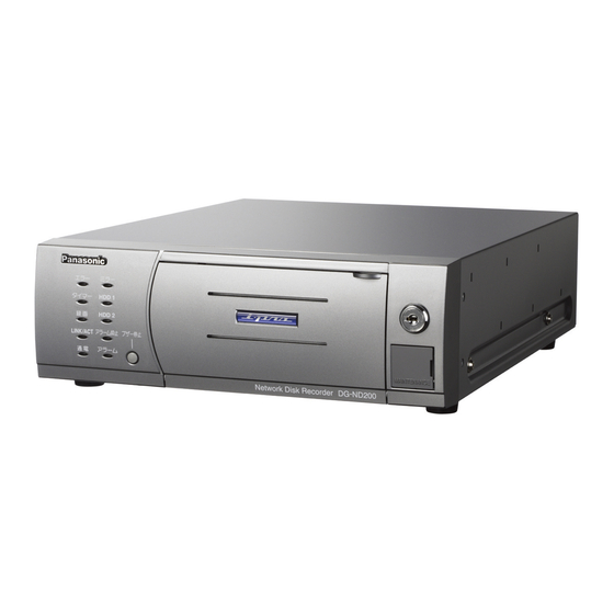
Panasonic WJ-ND200 Installation Manual
Network disk recorder
Hide thumbs
Also See for WJ-ND200:
- Setup instructions (85 pages) ,
- Operating instructions manual (69 pages) ,
- Specifications (2 pages)
Table of Contents
Advertisement
Quick Links
ER RO R
MI RR OR
TIM ER
HD D1
RE C
HD D2
LIN K
ALA RM
/AC T
BU ZZE R
SU SP EN D
ST OP
OP ER AT E
AL AR M
Before attempting to connect or operate this product,
please read these instructions carefully and save this manual for future use.
Network Disk Recorder
Model No.
N et w or k D
is k R ec or de
r W J- N D 20
0
Installation Guide
WJ-ND200
Advertisement
Table of Contents

Related Manuals for Panasonic WJ-ND200


Summary of Contents for Panasonic WJ-ND200
- Page 1 Network Disk Recorder Installation Guide WJ-ND200 Model No. ER RO R MI RR OR TIM ER HD D1 RE C HD D2 LIN K ALA RM /AC T BU ZZE R SU SP EN D ST OP OP ER AT E...
- Page 2 If you lose the fuse cover the plug must not be used until a replacement cover is obtained. A replacement fuse cover can be purchased from your local Panasonic CAUTION Dealer. RISK OF ELECTRIC SHOCK...
-
Page 3: Limitation Of Liability
For U.S.A The serial number of this product may be found on the sur- NOTE: This equipment has been tested and found to com- face of the unit. ply with the limits for a Class A digital device, pursuant to You should note the serial number of this unit in the space Part 15 of the FCC Rules. -
Page 4: Important Safety Instructions
Important Safety Instructions 1) Read these instructions. 2) Keep these instructions. 3) Heed all warnings. 4) Follow all instructions. 5) Do not use this apparatus near water. 6) Clean only with dry cloth. 7) Do not block any ventilation openings. Install in accordance with the manufacturer's instructions. 8) Do not install near any heat sources such as radiators, heat registers, stoves, or other apparatus (including amplifiers) that produce heat. -
Page 5: Table Of Contents
CONTENTS Limitation of Liability ........................... 3 Disclaimer of Warranty ..........................3 Important Safety Instructions ........................4 Precautions ..............................6 Preface ............................... 8 Features ..............................8 About these Operating Instructions ......................9 Trademarks and Registered Trademarks ....................9 Network Security ............................9 Major Operating Controls and Their Functions ................... -
Page 6: Precautions
Precautions • Refer all work related to the installation of this prod- It is recommended to keep the ambient operating temperature below 25 °C (77 °F) to prevent data uct to qualified service personnel or system installers. loss from disk clashes, etc. and replace them after around 18 000 hours (as indication) of operation. - Page 7 • Places to avoid • We recommend that you make a note of your settings and save them. This will help when you are required to Do not place the unit in the following places: • Places exposed to direct sunlight change the system configuration, or when unexpected •...
-
Page 8: Preface
Up to 16 cameras can be connected via a network and it is possible to record their camera pictures. It is possible to perform the settings or operate the WJ-ND200 (this unit) using a web browser installed on a PC connected to a network. Up to 4 PCs (web browsers) can access this unit concurrently and it is possible to perform the settings and operate this unit. -
Page 9: About These Operating Instructions
Adobe web site and install it. "WJ-ND200" or "ND200" shown in the illustrations used in these operating instructions indicate this unit or the WJ-ND200. Trademarks and Registered Trademarks • Microsoft, Windows, Internet Explorer, and ActiveX are either registered trademarks or trademarks of Microsoft Corporation in the United States and/or other countries. -
Page 10: Major Operating Controls And Their Functions
HDD1 HDD2 LINK ALARM BUZZER /ACT SUSPEND STOP ALARM OPERATE Network Disk Recorder WJ-ND200 HDD bay slot HDD1 FORMAT HDD2 FORMAT <Inside the front cover> !3 !2 q Timer indicator (TIMER) y Buzzer stop button (BUZZER STOP) Lights when the schedule recording is set, and blinks Press this button to stop the buzzer that started sound- while the schedule recording is being performed. - Page 11 o Mirroring indicator (MIRROR) Indicates the status of the mirroring mode. Refer to the operating instructions (PDF) for further information about the mirroring function. Lights green when the unit is in the mirroring mode. Blinks green when the unit is in the process of the data recovery.
-
Page 12: I Rear View
I Rear View SIGNAL GND ALARM 10/100BASE-T ALARM/CONTROL AC IN POWER q Network port 2. Fix the power cord using the brace as shown in the illustration below. Connect this unit to a network compatible with 10BASE- T or 100BASE-Tx to connect a PC/cameras via a net- work. -
Page 13: Rack Mounting
Rack Mounting Important • Do not install the unit above an appliance which generates heat such a power amplifier. When installing the unit below a heat-generating appliance, install it below the appliance with a space equivalent to about 1 unit {44 mm, 1.73"} separating them. -
Page 14: Connection
Connection The following are descriptions of how to connect the unit with PCs and cameras. Required devices and cables vary depending on how to connect them. Before starting the connections, check the required devices and cables for your environment. How to connect the unit with PCs and cameras Connect cameras and PCs using the network port on the rear of the unit. -
Page 15: Connection Between Cameras And Pcs
Connection between cameras and PCs When connecting the unit and PCs through a hub, use a LAN cable to connect between the unit and a hub. Cameras should also be connected through a hub using LAN cables. Important: When connecting the unit and a PC directly without using a hub, connect them using a cross LAN cable. <Connecting PCs using an ADSL line>... - Page 16 <Connecting multiple units> Network Camera Network Camera Network Camera Network Camera LAN cable LAN cable (Not provided: 10BASE-T/100BASE-Tx, (Not provided: 10BASE-T/100BASE-Tx, sategory 5, straight) category 5, straight) SIGNAL GND SIGNAL GND ALARM ALARM 10/100BASE-T 10/100BASE-T ALARM/CONTROL ALARM/CONTROL AC IN POWER AC IN POWER Unit no.1...
-
Page 17: I How To Use The Terminals Of The Alarm/Control Connector
I How to Use the Terminals of the ALARM/CONTROL Connector These terminals are used for emergency recording, auto time adjustment, taking measures against power outages, and when installing a buzzer, a lamp, or similar alarm device. The terminal pin array and connections are shown below. The connector to be used should be compatible with the pin configu- ration. - Page 18 G Connection for emergency recording When the external switch is turned ON, emergency recording will be started. Recording time and recording rate for emergency recording differ according to the settings of "Emergency REC" on the setup menu. (Refer to the setup instructions (PDF) for further information about the setup menu.) (Earth) (Emergency recording input) External switch...
- Page 19 • When "Auto Adjust Time" of "Time & Date" of "System" on the setup menu is set to "SLAVE" "Time Adjust Input" becomes available. When a signal output from other equipment is supplied to the time adjust I/O terminals between 00 minutes 00 seconds and 14 minutes 59 seconds every hour or between 45 minutes 00 seconds and 59 minutes 59 seconds every hour, the clock will be set to "00 minutes 00 seconds"...
- Page 20 G Connection with the Uninterruptible Power System (UPS) This is an example of connection with the uninterruptible power system (UPS) to be installed to protect from a power outage. When a signal is supplied to the outage detection input terminals from the uninterruptible power system (UPS), internal pro- cessing (stops recording safely) will be started to shut off the power supply for this unit.
-
Page 21: I How To Use The Terminals Of The Alarm Connector
I How to Use the Terminals of the ALARM Connector These terminals are used to connect the alarm devices, such as sensors, door switches, etc. The terminal pin array and connections are shown below. The connector to be used should be compatible with the pin configu- ration. - Page 22 G Alarm connection When a signal is supplied to the alarm input terminals (pin nos. 1 - 16) recording and the alarm action will be performed according to the settings. When an alarm device such as a buzzer, a lamp, etc., is installed outside, connect them to the alarm output terminals (pin nos. 9 - 12, pin nos.
-
Page 23: Turn On/Off The Power Of The Unit
Turn On/Off the Power of the Unit Turn on the power of the unit Insert the power plug to an outlet. 120 V AC 60 Hz, for NTSC model 220 V - 240 V AC 50 Hz for PAL model Note: Make sure the power source matches the power requirement of the model in use. -
Page 24: Check The Ip Address
Check the IP Address The following network settings can be checked on the setup menu ("Basic Setup" – "Comm"). (Refer to the setup instructions (PDF) for further information about the setup menu.) • DHCP • IP address • Subnet mask •... -
Page 25: How To Replace The Hard Disks
Network Disk Recorder WJ-ND200 Hold down the [USE] button respective to the hard disk to be replaced for 2 seconds or more. - Page 26 Key hole Close the front cover and turn the key counter- clockwise to lock the panel. Network Disk Recorder WJ-ND200 Check the contents of the hard disk. → It is possible to check the following relating to the hard disk on the "Disk Information" page of "Maintenance".
-
Page 27: Troubleshooting
Troubleshooting Check the following before requesting repair. Contact a dealer if a problem cannot be solved even after checking and trying the solution or if a problem is not described below, or when having a problem with installations. Check item/Remedy Page Problem •... - Page 28 Check item/Remedy Page Problem The HDD access indicator • The respective HDD is faulty. lights red. Inspect the power cord, power plug and connectors periodically. Check item/Remedy Problem The power cord insulation is damaged. • The power cord, plug and connectors are worn out. The power cord, plug and con- This may result in electric shock or a fire.
-
Page 29: Specifications
Dimensions 270 mm (W) x 88 mm (H) x 360 mm (D) {10-5/8" (W) x 3-1/2" (H) x 14-1/4" (D)} (excluding rubber feet and projections) Weight WJ-ND200 5.0 kg {11 lbs.} HDD type/function 2.5" removable HDD x2 Mirroring mode available (only when 2 HDDs are installed) - Page 30 Security Systems www.panasonic.com/security http://panasonic.net/ For customer support, call 1.877.733.3689 Executive Office: Three Panasonic Way 2H-2, Secaucus, New Jersey 07094 Zone Office Eastern: Three Panasonic Way, Secaucus, New Jersey 07094 Central: 1707 N. Randal Road, Elgin, IL 60123 Southern: 1225 Northbrook Parkway, Suwanee, GA 30024 Western: 6550 Katella Ave., Cypress, CA 90630...