Raymarine ST60 Owner's Handbook Manual
Depth instrument
Hide thumbs
Also See for ST60:
- Owner's handbook manual (64 pages) ,
- Operating manual (38 pages) ,
- Commissioning manual (24 pages)

Related Manuals for Raymarine ST60


Summary of Contents for Raymarine ST60
- Page 1 Distributed by Any reference to Raytheon or RTN in this manual should be interpreted as Raymarine. The names Raytheon and RTN are owned by the Raytheon Company.
- Page 2 ST60 Depth Instrument Owner’s Handbook Document number: 81038-3 Date: 1st April 2001...
- Page 3 © Copyright Raymarine Limited 2001...
-
Page 4: Table Of Contents
Introduction Contents Introduction ................v EMC conformance ............v Data inputs ............... vi SeaTalk ............... vi Stand alone operation ..........vi Remote control ..............vi Options ................vii Mounting options ............vii Depth transducers ............vii Parts supplied ..............viii Chapter 1: Operation ............. - Page 5 ST60 Depth Instrument Owner’s Handbook Transducer ..............7 Cabling ................ 7 2.2 Fault finding ..............8 Preliminary procedures ..........8 Fixing faults ..............8 Chapter 3: Installation ............11 3.1 Planning your installation ......... 11 Site requirements ............11 Transducer ............11 Instrument ............
- Page 6 Introduction Chapter 4: Calibration ............25 4.1 Introduction .............. 25 EMC conformance ............ 25 4.2 User calibration ............25 Procedure ..............25 Depth units ..............27 Depth offset ............... 27 Setting offset values ..........28 Shallow lock .............. 28 Pop-up pilot ............... 28 Leaving User calibration ...........
- Page 7 ST60 Depth Instrument Owner’s Handbook...
-
Page 8: Introduction
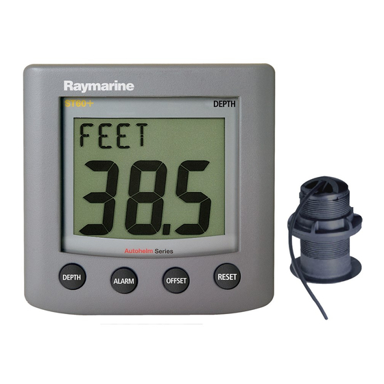
Thank you for purchasing a Raymarine product. We are sure your ST60 instrument will give you many years of trouble-free operation. This handbook describes how to install and use the Raymarine ST60 Depth instrument. This instrument provides accurate depth information in either feet, metres or fathoms, on a high quality Liquid Crystal Display (LCD). -
Page 9: Data Inputs
SeaTalk network. A slave instrument is not directly connected to a transducer but repeats information provided by other masters in the SeaTalk network. The ST60 Depth instrument can fulfil both master and repeater roles. Stand alone operation In Stand alone operation, the ST60 Depth instrument is connected only to the relevant transducer and does not display information from, or provide information to, any other instruments. -
Page 10: Options
Introduction Options Mounting options If you do not want to surface mount your ST60 instrument, options are available for: • Flush mounting. If you have ordered the flush mounting option a low-profile bezel and four fixing screws are also provided. -
Page 11: Parts Supplied
Spare spade terminals are also provided, to re-terminate the transducer cable if it has to be cut to facilitate installation. Note: The above packing list is for an ST60 Depth system. Where an instrument is purchased separately, a transducer is not included. - Page 12 Introduction ST60 Worldwide Depth Distributors Instrument Owner's Handbook D4438-2...
- Page 13 ST60 Depth Instrument Owner’s Handbook...
-
Page 14: Chapter 1: Operation
1.2 Normal operation Use the flow charts in this Chapter to operate your ST60 Depth instrument. The flow charts show the sequence of key presses and displays for the various operating tasks. All key presses are momentary unless otherwise stated. -
Page 15: Alarms
ST60 Depth Instrument Owner’s Handbook Switch on Current depth depth depth Press Maximum depth Minimum depth reset for 3 s to reset MIN or MAX display depth Reading depth values D4347-1 The current depth display provides depth-trend indicator arrows to show whether the depth is increasing or decreasing. - Page 16 Chapter 1: Operation alarm Shallow alarm alarm Deep alarm To enable/disable any alarm Press for 1 second reset (toggle action) To enter/exit adjust mode alarm Press offset reset together In adjust mode, use offset reset to increase to decrease, or Shallow anchor alarm alarm...
-
Page 17: Offsets
ST60 Depth Instrument Owner’s Handbook When the instrument is operating as a master, you can check the alarm thresholds and if necessary set them up (see Alarm thresholds flow chart). To do this, use the alarm key to select the required alarm threshold, then: •... -
Page 18: Contrast
This facility can be enabled or disabled during User calibration (see Chapter 4, Calibration). 1.5 Remote control When it is connected to SeaTalk, the ST60 Depth instrument can be controlled remotely with a SeaTalk Remote Keypad Unit. Remote control of an instrument is indicated by a REMOTE legend on the display, to indicate that the keypad has control. - Page 19 ST60 Depth Instrument Owner’s Handbook...
-
Page 20: Chapter 2: Maintenance And Fault Finding
This will not harm the instrument and can be cleared by increasing the illumination setting to Level 3. Periodically clean your ST60 instrument with a soft damp cloth. Do NOT use chemical and abrasive materials to clean the instrument. -
Page 21: Fault Finding
ST60 Depth Instrument Owner’s Handbook 2.2 Fault finding Preliminary procedures Changes in the electronic environment may adversely affect the operation of your ST60 equipment. Typical examples of such changes are: • Electrical equipment has recently been installed or moved aboard your vessel. - Page 22 Aerated water due to Ensure reading stabilises when under way boat wakes, propeller clear of disturbed water. wash etc. If you are unable to rectify a problem, contact the Raymarine Product Support Department or your own National Distributor, for assistance.
- Page 23 ST60 Depth Instrument Owner’s Handbook...
-
Page 24: Chapter 3: Installation
Chapter 3: Installation Chapter 3: Installation This chapter describes how to install the ST60 Depth instrument, and associated depth transducer. The transducer is fitted in the hull of the vessel and is connected to the rear of the instrument. The actual type of transducer depends on the type of hull in which it is to be installed. - Page 25 M78919 Retractable through hull Other transducer types are also available for specific requirements. For further details, contact your local Raymarine dealer. For accurate depth readings the transducer should be sited within the clear water flow areas indicated by the shaded areas in the following diagram.
-
Page 26: Instrument
ST60 instruments can be fitted either above or below deck, provided the rear of the instrument is sited where it is protected from contact with water. -
Page 27: Emc Guidelines
To minimise the risk of operating problems: • All Raymarine equipment and cables connected to it should be: • At least 1 m (3 ft) from any equipment transmitting or cables... -
Page 28: Suppression Ferrites
Raymarine. Connections to other equipment If your Raymarine equipment is going to be connected to other equipment using a cable not supplied by Raymarine, a suppression ferrite MUST always be fitted to the cable close to the Raymarine unit. -
Page 29: Procedures
Fitting the instrument The ST60 Depth instrument can be installed using one of a number of different mounting options: • Surface mounting. Gives a profile of approximately 24 mm. -
Page 30: Flush Mounting
6 mm above the panel fascia. Fitting the low-profile bezel In order to flush-mount your ST60 instrument, you must first replace the standard bezel with the low-profile bezel as follows: 1. Hold the instrument in both hands with the display towards you. - Page 31 ST60 Depth Instrument Owner’s Handbook D4537-2 2. Using both thumbs, gently press an upper corner of the instrument from the bezel, then remove the bezel from the instrument. Retain the rubber keypad which is released when the bezel is removed.
-
Page 32: Flush Mounting Procedure
Flush mounting procedure Flush mount your instrument (see the Flush mounting illustration) as follows: 1. Assemble the ST60 instrument and low-profile bezel as described under Fitting the low-profile bezel. 2. Ensure that: • The panel on which you intend to mount the instrument is between 3 mm and 20 mm thickness. -
Page 33: Bracket Mounting
To bracket mount your ST60 instrument, do so in accordance with the Control Unit Mounting Bracket Instruction Sheet. -
Page 34: Running Transducer Cable
Running transducer cable Each transducer type has a 14 m (45 ft) cable fitted with spade terminals for connection to the ST60 Depth instrument. The manner in which you run the cable will depend on the locations of the transducer and instrument. -
Page 35: Connecting Instruments
Where a SeaTalk system includes an autopilot, the power for the system is provided by the autopilot. A range of Raymarine SeaTalk extension cables is available to connect separated instruments. These cables are supplied with a SeaTalk connector fitted to each end. A junction box can be used to join cables. -
Page 36: Power Supply Connections
Chapter 3: Installation Power supply connections SeaTalk systems CAUTION When instruments are connected to SeaTalk, ensure that the power supply for the SeaTalk 12 V line is protected by a 5 A fuse. Systems with a large number of instruments on the SeaTalk bus may require connections to the power supply from each end of the system (‘ring-main’... - Page 37 ST60 Depth Instrument Owner’s Handbook 2. If the cable has not already been trimmed at the power supply end: a. Cut the cable to length and trim back an appropriate amount of the outer sheath. b. Cut back and insulate the yellow wire.
-
Page 38: Chapter 4: Calibration
Chapter 4: Calibration Chapter 4: Calibration 4.1 Introduction The ST60 Depth instrument is set up with factory-programmed default settings, so in order to optimise the performance of the instrument on board a particular vessel, the procedures in this Chapter must be carried out immediately after the completion of installation, and before the equipment is used for navigational purposes. - Page 39 ST60 Depth Instrument Owner’s Handbook Note: The User calibration entry screen will time out to the main display after 7 seconds. 3. Referring to the User calibration diagram and information in this Chapter, carry out the calibration procedure. Use the depth key to cycle from screen to screen and the offset and reset keys to set the required values at each screen.
-
Page 40: Depth Units
Chapter 4: Calibration Depth units You can set the units in which depth information is displayed to be either FEET, FATHOMS or METRES. Depth offset Depths are measured from the transducer to the sea bed. However, you can use the depth offset screen to apply offsets to this distance, so that the displayed depth reading represents either the depth from the keel or the depth from the water line (W/L). -
Page 41: Setting Offset Values
ST60 Depth Instrument Owner’s Handbook Setting offset values WARNING: The use of incorrect offset values could result in misleading depth information being displayed with a consequent risk of running aground. Use the offset (decrement) and reset (increment) keys to set the required offset value. -
Page 42: Leaving Intermediate Calibration
Chapter 4: Calibration To access the Intermediate calibration screens, hold down the depth and alarm keys for approximately 4 seconds. To set the instrument status: 1. Press the depth key to select the Instrument status screen. 2. Press the offset and reset keys simultaneously to enter adjust mode, then press either offset or reset to set the required status. -
Page 43: Dealer Calibration
ST60 Depth Instrument Owner’s Handbook 4.4 Dealer Calibration The Dealer calibration procedure (see Dealer calibration diagram) enables the following parameters to be set: • User calibration on/off. • Depth response. • Boat show mode on/off. Dealer calibration also gives access to the Factory defaults screen. This enables you to re-apply the factory settings if you want to reset the instrument to a known operating condition. - Page 44 Chapter 4: Calibration depth Hold down alarm for approximately 12 seconds Entry screen offset reset Calibration on/off depth depth Factory Response defaults At each screen use either offset reset to set the required values Boat show mode depth depth Dealer calibration D4354-1...
-
Page 45: Factory Defaults
ST60 Depth Instrument Owner’s Handbook Factory defaults You can use this screen to reset the operating parameters to the factory default values. If you want to apply the factory defaults, ensure the display shows YES, but if you want to retain the current values, ensure that the display shows NO NO. - Page 46 Drill 5mm (3/16in) diameter ST60 Surface Mount Template Machine hole 90mm (3.54in) diameter Shaded areas to be removed Drill 5mm (3/16in) diameter D4436-1...
- Page 48 ST60 Flush Mount Template 4 holes 6 mm diameter Shaded area to be removed 109 mm D4437-1...
- Page 50 During this period, except for certain products, travel costs (auto mileage and tolls) up to 100 round trip highway miles (160 kilometres) and travel time of 2 hours, will be assumed by Raymarine only on products where proof of installation or commission by authorized service agents, can be shown.
- Page 51 Factory Service Centers United States of America UK, Europe, Middle East, Far East Raymarine Inc Raymarine Ltd 22 Cotton Road, Unit D Anchorage Park, Portsmouth Nashua, NH 03063-4219, USA PO3 5TD, England Telephone: +1 603 881 5200 Telephone: +44 (0)23 9269 3611...