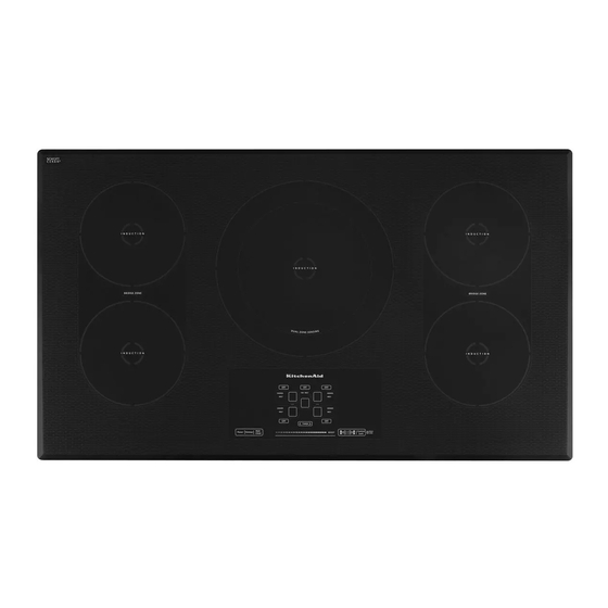
KitchenAid Kitchen Aid KICU500X Technical Education
Induction cooktop
Hide thumbs
Also See for Kitchen Aid KICU500X:
- Use and care manual (24 pages) ,
- Product dimensions (1 page)

Related Manuals for KitchenAid Kitchen Aid KICU500X


Summary of Contents for KitchenAid Kitchen Aid KICU500X
-
Page 1: Induction Cooktop
KAC-54 TECHNICAL EDUCATION INDUCTION COOKTOP Models: Jenn-Air Kitchen Aid Whirlpool KICU500X JIC4430X GIC3051X KICU509X JIC4536X KICU569X JOB AID W10346831... - Page 2 • Successfully perform necessary repairs. • Successfully return the cooktop to its proper operational status. WHIRLPOOL CORPORATION assumes no responsibility for any repairs made on our products by anyone other than authorized In-Home Service Professionals. Copyright © 2010, Whirlpool Corporation, Benton Harbor, MI 49022...
-
Page 3: Table Of Contents
TABLE OF CONTENTS Page GENERAL ..........................1-1 Cooktop Safety........................1-1 Model & Serial Number Designations ................1-2 Model & Serial Number Label And Tech Sheet Locations ..........1-3 Specifications ........................1-4 Induction Cooktop Components ..................1-6 INSTALLATION INFORMATION .................... 2-1 Installation Instructions....................... - Page 4 — NOTES — - iv -...
-
Page 5: General
GENERAL Cooktop Safety Your safety and the safety of others are very important. We have provided many important safety messages in this manual and on your appliance. Always read and obey all safety messages. This is the safety alert symbol. This symbol alerts you to potential hazards that can kill or hurt you and others. -
Page 6: Model & Serial Number Designations
Model & Serial Number Designations MODEL NUMBER PRODUCT GROUP K = KITCHENAID BRAND PRODUCT IDENTIFICATION EC = ELECTRIC COOKTOP GC = GAS COOKTOP IC = INDUCTION COOKTOP MERCHANDISING SCHEME C = CERAMIC GLASS C = ARCHITECT (GAS) D = DOWNDRAFT VENT K = STANDARD KITCHENAID P = COMMERCIAL STYLE S = (GAS) -
Page 7: Model & Serial Number Label And Tech Sheet Locations
Model & Serial Number Label And Tech Sheet Locations The Model/Serial Number label and Tech Sheet locations are shown below. Tech Sheet Location (On Bottom Of Cooktop In Plastic Bag)) Model & Serial Number Label Location... -
Page 8: Specifications
Specifications New Model KICU569X KICU500X KICU509X BL/SS (BL has beveled edge) Color BL/SS (BL has beveled edge) BL/SS (BL has beveled edge) 36" Cooktop Width 30" 30" Ceran Cooktop Material Ceran Ceran Number of Elements Left Front Type 6" Single 7"... - Page 9 Specifications (continued) JIC4536X GIC1306X New Model JIC4430X Color B/S (Black has beveled edge) 30" Cooktop Width 36" 30" Ceran Cooktop Material Ceran Ceran Number of Elements 6" Single Left Front Type 7" Bridge 7" Bridge 1800 W Left Front Power 2500 W 2500 W 9"...
-
Page 10: Induction Cooktop Components
Induction Cooktop Components A. Cooktop base G. User interface M. Assembly glass S. Harness fixing B. Power control board right H. Aluminum plate N. Frame T. Fan C. Power control board left I. Coil (6" [15.2 cm]) O. Coil (8" [20.3 cm]) U. -
Page 11: Installation Information
INSTALLATION INFORMATION Installation Instructions WARNING 4. Apply the adhesive provided in the kit to the back side of the brackets. Electrical Shock Hazard Disconnect power before servicing. Replace all parts and panels before operating. 5. Position brackets in the center of the Failure to do so can result in death or vertical centerline and align the upper electrical shock. - Page 12 Installation Instructions (continued) To Install Brackets into Wood Countertop: Install Cooktop WARNING Electrical Shock Hazard 1. Using 2 or more people, lower the cook Disconnect power before servicing. top into the cutout making sure the clips on each side of the cooktop line up with Replace all parts and panels before the brackets in the cutout.
- Page 13 Installation Instructions (continued) Make Electrical Connection 4-Wire Cable from Home Power Supply WARNING IMPORTANT: Use the 4-wire cable from home power supply in the U.S. where local codes do not allow grounding through neutral, New Branch circuit installations (1996 NEC), mobile homes and recreational vehicles, new con- struction, and in Canada.
- Page 14 Installation Instructions (continued) 3-Wire Cable from Home Power Supply - U.S. Only IMPORTANT: Use the 3-wire cable from home power supply where local codes permit a 3-wire connection. A. Cable from home power F. White wire (from home supply power supply) B.
-
Page 15: Product Operation
PRODUCT OPERATION Theory Of Induction Cooking negatively charged electrons in no Understanding The Makeup Of A Magnet particular order (as shown below), providing Metals are available to us in many different the characteristic of a magnet but have no shapes and make-up. Copper, Cast Iron, net magnetic ability. - Page 16 20 THOUSAND times per second. What do you think the electrons in the pan are doing? (creating heat very quickly). Induction cooking and the movement created in the cookware performs better at the lower frequency of 20KHz. Changing the frequency upwards to 60KHz reduces the efficiency of induction operation.
-
Page 17: Advantages Of Induction Cooking
Advantages Of Induction Cooking Cooler kitchens: • Of course the cooking vessel and the food Faster Cycle Time itself will radiate some of their heat into the • Heat is developed directly and instantly within cooking area—but compared to gas or other 1 second inside the pot or pan, allowing a forms of electrically powered cooking, much quicker startup than other heating... -
Page 18: User-Friendly
User-Friendly Noises that are Common to the Normal Operation of Induction Cooktops • Working conditions are improved with the absence of smoke and heat produced by Induction heating technology is based heating equipment. You can touch the outer on the capacity that certain metal materials casing without getting burned. -
Page 19: Overview Of Induction Cookware
turned off after being used if the detected temperature continues to be high. NOTE: All these noises are normal and inherent to induction technology, and they are not a sign of any breakdown. The noises that occur with greatest frequency are those with containers that have a “sandwich”... - Page 20 —NOTES—...
-
Page 21: Component Access
COMPONENT ACCESS Component Locations Coil Sensor (1 For Each Element) Left Rear Induction Right Rear Element Induction Assembly Element Assembly Aluminum Plate Thermofuse Thermofuse Left Front Right Front Induction Element Assembly User Interface Induction Element Assembly Line Fuses Filter (EMI) Board Right Cooling Fan Right Cooling Fan Left Cooling Fan... -
Page 22: Removing The Cooktop Glass
Removing the Cooktop Glass Unplug cooktop or disconnect power. WARNING Remove the cooktop from its mounting location, (see “Installation Instructions” in Section 2). Position the cooktop so that you can access the bracket screws below the cooktop glass. Remove the (6) T-20 Torx® head screws from the front, and side ceramic glass Electrical Shock Hazard brackets. -
Page 23: Removing The User Interface
Removing the User Interface Gently pull up on edges of User Interface WARNING board to release holder tabs, raise the user interface, and remove the board from the tab locations, see figure 1. Holder Tabs User Interface (back side) Electrical Shock Hazard Disconnect power before servicing. -
Page 24: Removing An Induction Element
Removing an Induction Element WARNING Left Rear Left Front Electrical Shock Hazard Right Rear Disconnect power before servicing. Right Front Replace all parts and panels before operating. Figure 2 Failure to do so can result in death or electrical shock. Connector Screws Unplug cooktop or disconnect power. -
Page 25: Removing A Cooling Fan
Removing a Cooling Fan WARNING a) Disconnect the 3-wire fan connector from power control board, see figure 3. b) Remove two screws from the cooling fan and lift the fan from the power control board, see figure 4. Left Cooling Fan Right Cooling Fan Electrical Shock Hazard Disconnect power before servicing. -
Page 26: Removing, Power Control Board, Fuses And Emi Board
Removing, Power Control Board, Fuses and EMI Board To replace the fuses on the Filter (EMI) WARNING board: a) Unplug cooktop or disconnect power. b) Remove the cooktop from installation. c) Remove cooktop glass. Remove the elements. Electrical Shock Hazard e) Remove the aluminum plate. -
Page 27: Terminal Block, Capacitor, Shunt Clip And Thermofuses
Terminal Block, Capacitor, Shunt Clip and Thermofuses WARNING Thermofuse Electrical Shock Hazard Disconnect power before servicing. Replace all parts and panels before operating. Failure to do so can result in death or electrical shock. To access the terminal block, shunt clip and thermofuses: Unplug cooktop or disconnect power. - Page 28 —NOTES—...
-
Page 29: Component Testing
COMPONENT TESTING Before testing any of the components, perform ohms-per-volt DC, or greater. the following checks: • Check all connections before replacing • The most common cause for control failure components, looking for broken or loose is corrosion on connectors. Therefore, wires, failed terminals, or wires not pressed disconnecting and reconnecting wires will into connectors far enough. -
Page 30: Component Testing Chart
Component Testing (continued) WARNING Electrical Shock Hazard Disconnect power before servicing. Replace all parts and panels before operating. Failure to do so can result in death or electrical shock. Component Testing Chart t l i f Power control board (PC) from Filter (EMI) Board Left and right Power control board (PC) to blower fan J205 - (00) - (22) -
Page 31: Coil Burner
Component Testing (continued) Coil Burner The resistance of the coil differs according to the size of the coil. Coil Sensor (S1) Coil Sensor This sensor reduces power output from the burner before it completely fails. Coil Sensor: begins at 400°F (210°C) to gradually reduce the power output of the element, reduces the power output down to zero power at 440°F (226°C), sensor opens and completely fails at 482°F (250°C). -
Page 32: Strip Circuit
Component Testing (continued) Strip Circuit This is a simplified strip circuit of the operation of a typical burner. You can see what components are working during the operation of a burner. -
Page 33: Troubleshooting
TROUBLESHOOTING For Service Technicians Only Before testing any of the components, perform • Check all connections before replacing the following checks: components, looking for broken or loose wires, failed terminals, or wires not pressed • The most common cause for control failure into connectors far enough. -
Page 34: Failure/Effor Codes
Troubleshooting (continued) Failure/Error Codes 11. Disconnect power. If all the lights on the User Interface are Off 12. Change both control boards. and there is no response from the cooktop, complete the following steps: 13. Replace all parts and panels before operating. -
Page 35: Type 1
Troubleshooting (continued) Failure Codes Failure/Error Code Types There are 3 types of failures associated with the cooktop. The description of these failures and the impact they will have on the rest of the cooktop are listed in the following: Type 1 This is showing a TYPE 1 failure code…. - Page 36 Troubleshooting (continued) WARNING Electrical Shock Hazard Disconnect power before servicing. Replace all parts and panels before operating. Failure to do so can result in death or electrical shock. Failure/Error Codes Service Code Failure Description Type of Failure Repair Suggestions Shown on Display F-12 Coil under current Type 1...
- Page 37 Troubleshooting (continued) Failure Description Type of Failure Repair Suggestions Service Code Shown on Display F-36, F37 Temperature sensor is not working Type 1 Disconnect power. Check that the temperature sensor is between 184,000 Ω - 292,000 Ω at room temperature and is rmly plugged in. If the sensor is not between 184,000 Ω...
- Page 38 go to Step 11. 11. Disconnect power. 12. Check the continuity of the fuses on the EMI board. If either of the fuses is blown, replace with a new one. 13. Replace all parts and panels before operating. 14. Reconnect power and check that it is working. If it is not working, Troubleshooting (continued) go to Step 15.
-
Page 39: Control Board Indicator Light
Troubleshooting (continued) Control Board Indicator Light Green 240VAC connection with top of insulator open These LEDs are mainly used in the labs and for engineering evaluations. However, the technician should consider a blinking red light as something not properly working inside the system. - Page 40 —NOTES—...
-
Page 41: Wiring Diagram
WIRING DIAGRAM 30˝ COOKTOP 208 - 240V Ground To Burner Box Power Cord Main Connection L1 L1 L2 L2 Red cable From 208VAC to From 208VAC to 240VAC 240VAC 60 Hz 208 - 240V Black cable 60Hz 60 Hz From 208VAC to Yellow cable 240V 240VAC... - Page 42 — NOTES —...
- Page 43 PRODUCT SPECIFICATIONS WARRANTY INFORMATION SOURCES IN THE UNITED STATES: FOR PRODUCT SPECIFICATIONS AND WARANTY INFORMATION CALL: FOR WHIRLPOOL PRODUCTS: 1-800-253-1301 FOR KITCHENAID PRODUCTS: 1-800-422-1230 FOR ROPER PRODUCTS: 1-800-447-6737 FOR TECHNICAL ASSISTANCE WHILE AT THE CUSTOMER’S HOME CALL: THE TECHNICAL ASSISTANCE LINE: 1-800-832-7174...