Brother MFC4820C Service Manual
Facsimile equipment
Hide thumbs
Also See for MFC4820C:
- User manual (361 pages) ,
- Quick setup manual (28 pages) ,
- Service manual (7 pages)
Table of Contents
Advertisement
Quick Links
Advertisement
Chapters
Table of Contents
Troubleshooting

Related Manuals for Brother MFC4820C


Summary of Contents for Brother MFC4820C
- Page 1 FACSIMILE EQUIPMENT SERVICE MANUAL MODEL: MFC4820C/MFC4420C...
- Page 2 © Copyright Brother 2003 All rights reserved. No part of this publication may be reproduced in any form or by any means without permission in writing from the publisher. Specifications are subject to change without notice.
- Page 3 PREFACE This publication is a Service Manual covering the specifications, construction, theory of operation, and maintenance of the Brother facsimile equipment. It includes information required for field troubleshooting and repair--disassembly, reassembly, and lubrication--so that service personnel will be able to understand equipment function, to rapidly repair the equipment and order any necessary spare parts.
- Page 4 SAFETY PRECAUTIONS To Use the Machine Safely Save these instructions for later reference. There are high voltage electrodes inside the Do not handle the plug with wet hands. machine. Before you clean the machine or Doing this might cause an electrical shock. clear a paper jam, make sure you have unplugged the power cord from the power outlet.
- Page 5 Lightning and power surges can damage this product! We recommend that you use a quality surge protection device on the AC power line and on the telephone line, or unplug the lines during a lightning storm. Do not use this product near appliances that use water, in a wet basement or near a swimming pool. Avoid using a telephone other than a cordless type during an electrical storm.
- Page 6 CHAPTER PARTS NAMES & FUNCTIONS...
- Page 7 CHAPTER 1 PARTS NAMES & FUNCTIONS CONTENTS EQUIPMENT OUTLINE ....................1-1 CONTROL PANEL......................1-3 COMPONENTS........................1-5...
-
Page 8: Equipment Outline
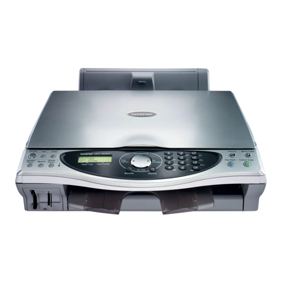
1.1 EQUIPMENT OUTLINE Front view (6) Paper support (5) Paper tray (4) Paper guide (7) Document cover (3) PhotoCapture™ media slot (8) Scanner cover (2) Output paper support (9) Scanner cover release lever (1) Output paper support extension (10) Control panel Rear view (12) Telephone line jack (13) USB interface connector... - Page 9 Name Description Output paper support extension Pull it out to prevent the printed paper from falling. Printed paper comes out here. Output paper support Insert your media card into the appropriate slot to print a digital PhotoCapture™ media slot photo. Paper guide Press and slide it to fit the paper width.
- Page 10 1.2 CONTROL PANEL A. Telephone and Message Center keys B. Liquid Crystal Display (LCD) On/Off Displays messages on the screen to help you set up and use your machine. Let’s you activate the Message Center and blinks if you did not play your voice messages. Date Current receive Play/Record...
- Page 11 C. Navigation keys D. Dial Pad Copy Options Use these keys to dial telephone and fax numbers and as a keyboard for entering information into the Copy Options machine. You can quickly and easily select temporary settings The # key lets you temporarily switch the dialing for copying.
- Page 12 Ink cartridge PCB Rear cover L USB PCB Ink absorber box Lower cover Enclosure cover Media module Power supply PCB NCU PCB Handset mount* Main PCB Modular PCB* Driver PCB Bottom plate * Provided on the MFC4820C. 1 -5...
- Page 13 CHAPTER SPECIFICATIONS...
-
Page 14: Table Of Contents
CHAPTER 2 SPECIFICATIONS CONTENTS GENERAL ........................2-1 2.1.1 General Specifications ..................2-1 2.1.2 Paper Specifications.....................2-1 2.1.3 Printable Area.......................2-4 2.1.4 Environmental Conditions ..................2-5 OTHERS...........................2-6... -
Page 15: General
2.1 GENERAL 2.1.1 General Specifications 16MB Memory Capacity Up to 100 sheets (20 lb.) Auto Sheet Feeder (ASF) Ink Jet Printer Type Piezo with 75 x 4 nozzles Print Method 16 characters x 2 lines, backlight Liquid Crystal Display (LCD) 50 to 95ºF (10 to 35ºC) Operating Environment 68 to 91ºF (20 to 33ºC) - Page 16 Paper Capacity of the Paper Tray Paper Type Paper Size Number of Sheets Plain Paper (Cut Sheet) Letter, Executive, A4, A5 100 of 20 lb. (80 g/m Up to 0.39 in. (10 mm) Legal 50 of 20 lb. (80 g/m Inkjet Paper Letter Glossy Paper...
- Page 17 Paper Capacity of the Output Paper Support Output Paper Support Up to 30 sheets of 20 lb. (80 g/m (Transparencies and glossy paper must be picked up from the output paper support one page at a time to avoid smudging.) Do not use paper or envelopes: that are damaged, curled, wrinkled, or irregularly shaped 0.08 in.
-
Page 18: Printable Area
2.1.3 Printable Area The printable area depends on the settings in the application you are using. The figures below show the unprintable areas on cut sheet paper and envelopes. Cut Sheet Paper Envelopes unprintable area Paper Paper Size (1) Top (2) Bottom (3) Left (4) Right... -
Page 19: Environmental Conditions
2.1.4 Environmental Conditions 2 -5... -
Page 20: Others
2.2 OTHERS (1/6) Model Name MFC-4420C MFC-4820C GENERAL Print Engine 2 head BH: 75 nozzles/color 2 head BH: 75 nozzles/color Technology Inkjet Inkjet Scanning Method CPU Speed RISC-100MHz RISC-100MHz Back up Clock Yes (1 hour) Yes (1 hour) Operating Environment Temperature 10 - 35 (20-33) degrees Centigrade 10 - 35 (20-33) degrees Centigrade Humidity... - Page 21 (2/6) Model Name MFC-4420C MFC-4820C LIST/REPORT Activity Report/Journal Report Yes (up to 200) Yes (up to 200) Transmission Verification Report Yes (in Menu Table) Yes (in Menu Table) Cover page Help List Yes (in Menu Table) Yes (in Menu Table) Call Back Message Caller ID List Quick Dial List...
- Page 22 Approx. 6 sec./page (A4 standard) Approx. 6 sec./page (A4 standard) Memory Transmission (ITU-T Test Chart #1) Up to 400 Pages (MMR) Up to 400 Pages (MMR) Memory Transmission (Brother Chart) UP to480 Pages (MMR) UP to480 Pages (MMR) ECM (Error Correction Mode) Error Re-Transmission...
- Page 23 (4/6) Model Name MFC-4420C MFC-4820C COLOR PRINTER Color/Mono Color Color Engine Type Resolution (dpi) up to 2400x1200 dpi up to 2400x1200 dpi Speed (ppm) Simple 13/11ppm (Mono/Color: 600x150 dpi) 13/11ppm (Mono/Color: 600x150dpi) Speed (ppm) Duplex First print out time (from READY mode *4) W arm up Time (from SLEEP mode) 0 seconds 0 seconds...
- Page 24 Mac OS 8.6 - 9.2, 10.1,10.2.1 or greater Scanner Driver *not available for OS 10.1 Brother TWAN: Mac OS 8.6 - 9.2,10.2.1 or greater Brother TWAN: Mac OS 8.6 - 9.2,10.2.1 or greater PC Fax Sending Driver * 10.2.0 users need to Mac OS 8.6 - 9.2 **...
- Page 25 (6/6) Model Name MFC-4420C MFC-4820C PHOTO CAPTURE CENTER Smart Media (3.3V) Smart Media (3.3V) Acceptable Media Compact Flash (Type-1/2, excl. Micro-Drive) Compact Flash (Type-1/2, excl. Micro-Drive) Memory Stick Memory Stick Paper Handling Size (Paper Tray) LTR, LGL, A4, Postcard (4W x6H) LTR, LGL, A4, Postcard (4Wx6H) Paper Handling Size (Manual Slots) Paper Handling Size (MP)
- Page 26 CHAPTER SETTING UP OF THE MACHINE...
- Page 27 CHAPTER 3 SETTING UP OF THE MACHINE CONTENTS CONDITIONS REQUIRED FOR INSTALLATION ............3-1 3.1.1 Environmental Conditions ..................3-1 3.1.2 Basic Layout of Machine Set-up Location ............3-1 UNPACKING THE MACHINE ..................3-2 INSTALLATION WORK ....................3-3 3.3.1 Removing the Protective Parts................3-3 3.3.2 Attaching the Paper Tray..................3-3 3.3.3 Loading Paper ......................3-4 3.3.4...
-
Page 28: Conditions Required For Installation
3.1 CONDITIONS REQUIRED FOR INSTALLATION Any machine is likely to be influenced by the environment of the set-up location. If the machine is set-up in an inappropriate location, the machine may not perform as expected. Therefore, the following factors should be taken into consideration before deciding where to set-up the machine. 3.1.1 Environmental Conditions The machine should not be set up in the locations referred to in the following items (a) through (d) which specify inappropriate locations for set-up. -
Page 29: Unpacking The Machine
3.2 UNPACKING THE MACHINE The equipment consists of the following major components: 3 -2... -
Page 30: Installation Work
3.3 INSTALLATION WORK 3.3.1 Removing the Protective Parts (1) Remove the protective tape. Do NOT connect the USB cable. Connecting the USB cable is done when installing the driver. 3.3.2 Attaching the Paper Tray (1) Insert the paper tray from above into the back of the machine. Paper tray 3 -3... -
Page 31: Loading Paper
3.3.3 Loading Paper NOTE: You can load up to 100 sheets of 20 lb (75 g/m ) paper. (1) Fan the stack of paper well to avoid paper jams and mis-feeds. (2) Unfold the paper support and then press and slide the paper guide to fit the paper width. Paper support Paper guide (3) Gently insert paper. -
Page 32: Setting The Handset
3.3.4 Setting the Handset (1) Connect the curled handset cord to the machine and the other end to the handset. 3.3.5 Connecting the Telephone Line Cord and Power Cord (1) Connect the power cord. Power cord (2) Connect the telephone line cord. Connect one end of the telephone line cord to the jack on the machine marked LINE and the other end to a modular wall jack. - Page 33 WARNING The machine must be grounded using a 3-prong plug. Since the machine is grounded through the power outlet, you can protect yourself from potentially hazardous electrical conditions on the telephone network by keeping the power to your machine on when you connect it to a telephone line. Similarly, you can protect yourself when you want to move your machine by disconnecting the telephone line first and then the power cord.
-
Page 34: Installing The Ink Cartridges
3.3.6 Installing the Ink Cartridges (1) Make sure that the power is turned on. The LCD shows; (2) Pull the scanner cover release lever to open the scanner cover and lift it to the opening position. Scanner cover release lever Scanner cover (3) Lift the output paper support and ink cartridge cover. - Page 35 (6) Close the ink cartridge cover, the output paper support and the scanner cover. When the machine is setup for the first time, the machine will prepare the Brother unique ink tube system for use for the first time. This process will occur only once, the first time ink cartridges are installed.
- Page 36 • Brother strongly recommends that you do not refill the ink cartridges provided with your machine. We also strongly recommend that you continue to use only Genuine Brother Brand replacement ink cartridges. Using or attempting to use potentially incompatible inks and/or cartridges in your machine may cause damage to the machine itself and/or it may result in unsatisfactory print quality.
-
Page 37: Color Block Quality And Alignment Checks
3.3.7 Color Block Quality and Alignment Checks (1) After the cleaning cycle is finished, the LCD shows; Fax Start (2) Make sure the paper is loaded in the paper tray. Press the key. (3) The machine starts printing the PRINT QUALITY CHECK SHEET (only during initial ink cartridge installation). - Page 38 (3) The LCD asks you if the print quality is OK for each color. Press the 1 or 2 key on the dial pad. When you have finished selecting the 1 key (YES) or the 2 key (NO) for each color, the LCD shows: Press the 1 key (YES), and then machine starts cleaning the colors.
- Page 39 Step B: Alignment Check (1) The LCD shows: Check the 600 DPI and 1200 DPI test print to see if No.5 most closely matches the OK sample (No.0). Press the 1 key if No.5 matches it. If another test print number is a better match for either 600 DPI or 1200 DPI, press the 2 key to select NO and go to (2).
- Page 40 CHAPTER THEORY OF OPERATION...
- Page 41 CHAPTER 4 THEORY OF OPERATION CONTENTS OVERVIEW ........................4-1 MECHANISMS .........................4-2 4.2.1 Document Scanner Mechanism ................4-4 4.2.2 Paper Feeding Mechanism ..................4-6 4.2.2.1 Auto Sheet Feeder (ASF) mechanism ............4-7 4.2.2.2 Paper feeding and ejection mechanism............4-9 4.2.3 Printing mechanism....................4-11 4.2.3.1 Ink supply and ink jet mechanism ..............4-12 4.2.3.2 Head cap mechanism ................4-21 4.2.3.3...
-
Page 42: Overview
4.1 OVERVIEW Compact Flash SmartMedia Host Memory Stick Control Media panel interface station Fax Control Section Printer Control Section Print data Paper feeding Line Scanner unit Ink jet printer unit Power mechanism supply - CIS unit - Print head unit - ASF motor - CIS travel - Carriage motor... -
Page 43: Mechanisms
4.2 MECHANISMS This facsimile machine consists of the following mechanisms and uses six motors, encoders, sensors and thermistors. DOCUMENT SCANNER MECHANISM PAPER FEEDING MECHANISM PRINTING MECHANISM (As viewed from the right) Document scanner CIS travel motor mechanism Paper feeding - Auto Sheet Feeder (ASF), ASF motor (stepping motor) mechanism registration, paper feeding, and... - Page 44 - Scanner/ink slot cover open sensor - ASF switch - Registration sensor - Paper width sensor (Media sensor) - Ink cartridge sensors - Purge cam HP switch - Hook switch (provided on the MFC4820C) Thermistors - Head thermistor - Casing internal temperature thermistor 4 -3...
-
Page 45: Document Scanner Mechanism
4.2.1 Document Scanner Mechanism This mechanism consists of the document cover ASSY and scanner unit. The scanner unit consists of a scanner top cover, CIS unit, CIS drive mechanism, and scanner base. For details on the sensors, refer to Section 4.2.4. Document cover CIS rail Scanner top cover... - Page 46 If you open the document cover ASSY, place a sheet of a document (or a book opened to the desired page) face down on the glass of the scanner top cover, close the document cover, and start the scanning operation, the CIS drive mechanism will start up. This causes the CIS travel motor to rotate and its rotational torque to be subsequently transmitted via the gear train to the CIS drive belt.
-
Page 47: Paper Feeding Mechanism
4.2.2 Paper Feeding Mechanism The paper feeding mechanism consists of the auto sheet feeder (ASF) mechanism and paper feeding and ejection mechanism. The former is driven by the ASF motor and pulls in the paper; while the latter is driven by the paper feed motor and registers the leading edge of the pulled-in paper and feeds and ejects the paper. -
Page 48: Auto Sheet Feeder (Asf) Mechanism
4.2.2.1 Auto Sheet Feeder (ASF) mechanism The ASF mechanism, which is driven by the ASF motor (stepping motor), pulls in paper set in the paper tray into the printer unit, sheet by sheet. When the machine is not in printing, the mechanism holds* the paper in the tray to prevent it from slipping into the printer unit. - Page 49 Whether the paper stoppers are lifted up or down is signaled to the controller by the ASF switch. Paper feed – step 2 Next, the ASF motor rotates counterclockwise (as viewed from the output shaft). Its rotational torque is transmitted to the ASF roller shaft gear, but the direction of gear rotation is the opposite of that in step 1.
-
Page 50: Paper Feeding And Ejection Mechanism
4.2.2.2 Paper feeding and ejection mechanism The paper feeding and ejection mechanism is driven by the paper feed motor (DC motor), located on the rear left side of the engine unit, through the two PF timing belts and a gear train. The rotational torque of the paper feed motor is transmitted via PF timing belt 135 to the PF roller pulley. - Page 51 Controlling the paper stop position To make the paper feed motor (DC motor) stop paper with precision during printing, the controller controls the motor using PID control (Proportional, Integral and Differential control) using the PF encoder. The controller sets parameters suitable for the paper feed amount, enabling the motor to stop in position with high precision in a short space of time.
-
Page 52: Printing Mechanism
4.2.3 Printing mechanism The printing mechanism consists of the "ink supply and ink jet mechanism," "head capping mechanism," "purge mechanism" and "carriage drive mechanism." The former two are driven by the air pump motor and purge motor and the latter two by the carriage motor. The ink supply and ink jet mechanism uses ink cartridge sensors. -
Page 53: Ink Supply And Ink Jet Mechanism
4.2.3.1 Ink supply and ink jet mechanism The ink supply and ink jet mechanism is illustrated below. When the machine is first turned on after shipment, it will carry out an initial purge in which the air pump & motor module and the purge unit supply the print head unit with ink from the four ink cartridges (black, cyan, magenta, and yellow) via the needle tubes. - Page 54 (with the battery cover* or rear cover S** removed). (*For the MFC4820C, **For the MFC4420C.) If you replace the module with a new one, you need to enter a property code (19-digit) into the EEPROM in the maintenance mode (Function code 68) and replace the property label with the one that comes with the new module.
- Page 55 [ 2 ] Structure of the print head unit The print head unit consists of an ink jet head, manifold and air vent unit. Manifold Air vent unit From the needle tube Ink jet head Print Head Unit Print head units also have their own individual properties. When a unit is installed in the machine, its property data is stored in the EEPROM on the driver PCB.
- Page 56 If the controller issues a print command, a biased voltage will be applied to all electrodes on the surface of the piezoelectric ceramic so that each ceramic actuator will be distorted, as shown with the broken lines in the figure below. If the electrodes on a target channel are deenergized in response to drive signals, then the associated piezoelectric ceramic actuator returns to the previous form so that the ink in the manifold will be sucked out to the channel.
- Page 57 Role as an air damper The air in the upper section of the manifold also functions as an air damper that dampens the dynamic pressure of ink in the needle tubes produced by the moment of inertia when the carriage travels.
- Page 58 [ 3 ] Structure of an ink cartridge The illustration below is the sectional view of an ink cartridge. The ink cartridge is a one-use type that cannot be refilled, as described later. It is, therefore, made of flammable materials that will produce no noxious materials and contains no metal so that the effects on the environment are minimized.
- Page 59 If the controller detects an ink empty state, it will stop the subsequent printing operation and prompt the user to replace the ink cartridge. The ink empty signaling system designed for this machine is: first the software counter (that counts the droplets jetted out from each of the ink cartridges after replacement) indicates "near empty"...
- Page 60 Ink cartridge refill-protect mechanism As shown below at left, in the production process of the ink cartridges used with this machine, an ink cartridge will be filled with ink by vacuum suction and liquid processing. Once the cartridge has been filled, two rubber pieces will be forced into the cartridge and sealed up with tape, as illustrated below at right.
- Page 61 [ 4 ] Structure of the needle tubes The structure of a needle tube is shown below. The innermost layer utilizes FEP tubing, which provides an excellent and long-term barrier against air getting into the tubes and against ink evaporation. The outer layer utilizes silicon tubing which features superior flexibility and durability to the degree necessary to withstand the high-speed movement of the print head unit as well as long-term constant and extreme bending.
-
Page 62: Head Cap Mechanism
4.2.3.2 Head cap mechanism Shown below is a head cap mechanism that covers the print heads tightly to prevent the head nozzle meniscuses (shown on page 4-12) from drying up when they are not in use. This mechanism further prevents those meniscuses from breaking up as a result of changes in pressure inside the head caps due to changes in the operating environment. -
Page 63: Purging Mechanism
4.2.3.3 Purging mechanism [ 1 ] Overview of the purge drive The purge mechanism is driven by the purge motor (stepping motor) in the purge unit, and restores the machine’s ability to jet out ink by sucking up ink deteriorated in quality from the head nozzles. The purge motor also pushes up the vent rods in the purge unit and, as described in Section 4.2.3.1, [ 2 ], (3), expels the air trapped in the print head unit manifold. - Page 64 When the purge motor rotates clockwise (as seen from the motor output shaft), the rotary torque is transmitted to the tube pump via the planet gear, as shown in the figure below. Ink that has been sucked up is delivered by the tube pump to the ink absorber box. Purge motor Planet gear Tube rollers...
- Page 65 Role of the pump switching unit • Interlocked with the purge cam, the pump switching unit switches application of the pump's negative pressure between the black/cyan head nozzles, yellow/magenta head nozzles, vent rod unit and opening to the atmospheric air. When the purge cam is in the home position (that is, the print heads are capped), the head caps are opened to the atmospheric air inside the pump switching unit.
- Page 66 Role of the vent rod unit The vent rod unit is driven by the cap cam in the same way as the head cap unit (refer to Section • 4.2.3.2). Its four vent rods pop up to push up the corresponding release rods in the air vent unit of the print head unit.
- Page 67 [ 2 ] Purge types, time required and amount of ink used To perform the Amount Purge Time purge in Contents of ink type required maintenance used mode: Initial This purge is performed automatically when the 2.5 to 3.21 cc Press the 4 key purge power is first applied by the user after shipment.
- Page 68 Cyan Reset purge Purge type Initial purge Normal purge Reset purge substitute + suction Purge timing purge First automatic cleaning after √ purchase Cleaning initiated using the √ √ √ function panel Cleaning after test printing √ √ √ After ink cartridge replacement √...
- Page 69 When the facsimile machine leaves the factory, both the ink supply tubes and print heads are filled with ink. If the machine is stored for a long period without being used, the air in the ink will develop into bubbles. To expel these air bubbles, when ink cartridges are set in place and the power is turned on for the first time after shipment, an initial purge starts automatically.
-
Page 70: Carriage Drive Mechanism
4.2.3.4 Carriage drive mechanism The carriage, on which the print head unit and the ink supply section of the needle tube ASSY are mounted, travels to the right and left when driven by the carriage motor (DC motor). The motor rotation is transmitted to the CR timing belt (1/24 inch pitch). The carriage, which is supported and guided by the carriage rail, is secured to the CR timing belt. - Page 71 Print head skew compensation by adjusting the carriage in the direction of Zθ The carriage, on which the print head unit is mounted, is secured onto the carriage rail via the eccentric bushing. Print head units are classified into five ranks depending upon the skew of the head nozzles.
-
Page 72: Sensors And Actuators
Mechanical switch Purge unit Ink cartridge sensors (x 4) Photosensor Ink cartridge sensor PCB Hook switch PCB in the Hook switch (on the MFC4820C) Mechanical switch handset Air pump motor encoder sensor Photosensor Air pump & motor module Head flat cable of the... - Page 73 • The carriage motor (CR) encoder sensor monitors the current carriage position and carriage travel speed. If the carriage travel speed varies abnormally, the controller regards it as a paper jam. • The paper feed motor (PF) encoder sensor monitors the rotation angle and speed of the PF motor (DC motor), allowing the controller to optimize the paper feed amount and speed.
- Page 74 ASF switch (Sensor PCB on the ASF) (Purge unit) Registration sensor Purge cam HP switch Registration sensor actuator (Ink cartridge sensor PCB) (Handset) Ink cartridge Hook switch actuator* sensors Hook switch* (Hook switch PCB)* Scanner/ink slot cover open sensor (Control panel PCB) Scanner open sensor actuator Air pump motor encoder sensor Ink slot cover open sensor actuator...
-
Page 75: Control Electronics
4.3 CONTROL ELECTRONICS 4.3.1 Configuration The hardware configuration of the facsimile machine is shown below. The wiring diagram is given in Appendix 6. Line NCU PCB External telephone Compact Flash Media PCB SmartMedia Memory Stick USB PCB Handset* Modular PCB* Microphone/Headphone* Hook Main PCB... - Page 76 CHAPTER ROUTINE MAINTENANCE...
- Page 77 CHAPTER 5 ROUTINE MAINTENANCE CONTENTS CLEANING ........................5-1 5.1.1 Cleaning the Exterior of the Machine ..............5-1 5.1.2 Cleaning the Scanner Glass.................5-1 5.1.3 Cleaning the Purge Unit ..................5-2 5.1.4 Cleaning the Print Head Unit................5-3 REPLACING THE INK CARTRIDGES ................5-4 5.2.1 Replacing the Ink Cartridge..................5-4 5.2.2 Checking the Ink Volume ..................5-6...
-
Page 78: Cleaning
5.1 CLEANING If the machine is stained or soiled, clean it as described below. 5.1.1 Cleaning the Exterior of the Machine Gently wipe off the machine with a dry, soft cloth. NOTE: Never use benzene, thinner, or other organic solvents. Do not use alcohol or a cloth dampened with alcohol. -
Page 79: Cleaning The Purge Unit
WARNING Do not clean the printing unit (engine unit). Never touch the shaded section as shown below. Doing so may stain your hands with ink or break the ink tubes. 5.1.3 Cleaning the Purge Unit (1) Unplug the power cord from the wall socket. (2) Plug the power cord again. -
Page 80: Cleaning The Print Head Unit
5.1.4 Cleaning the Print Head Unit (1) Remove the print head unit from the carriage. (2) Soak a Rubycel stick in "Glycerol cleaner." (3) Clean the printing surface of the print head unit by rolling the Rubycel stick lightly on the printing surface. -
Page 81: Replacing The Ink Cartridges
5.2 REPLACING THE INK CARTRIDGES Your machine is equipped with an ink dot counter that automatically monitors the ink level in each color cartridge. When the counter detects an ink cartridge is out of ink, the machine will notify you with a message "INK EMPTY"... - Page 82 (5) Each color has its own correct position. Insert the new ink cartridge into its carriage by pressing until it clicks. Insert until it clicks New ink cartridge (6) After installing the ink cartridges, close the ink cartridge cover, output paper support and scanner cover.
-
Page 83: Checking The Ink Volume
Use unopened ink cartridges by the expiration date written on the cartridge package. Brother strongly recommends that you do not refill the ink cartridges provided with your machine. We also strongly recommend that you continue to use only Genuine Brother Brand replacement ink cartridges. - Page 84 CHAPTER DISASSEMBLY/REASSEMBLY...
- Page 85 CHAPTER 6 DISASSEMBLY/REASSEMBLY CONTENTS DISASSEMBLY/REASSEMBLY ..................6-1 Safety Precautions.......................6-1 Tightening Torques......................6-2 Preparation ........................6-3 How to Access the Object Component ................6-3 Disassembly Flowchart....................6-4 6.1.1 Draining the Ink from the Ink Tubes --This must be performed before removing the print head unit or engine unit-- ..6-5 6.1.2 Print Head Unit .....................6-6 6.1.3...
-
Page 86: Disassembly/Reassembly
6.1 DISASSEMBLY/REASSEMBLY Safety Precautions To prevent the creation of secondary problems through mishandling, observe the following precautions for maintenance work. (1) Unplug the power cord from the power outlet before replacing parts or units. When accessing to the power-related sections, be sure to unplug the power cord from the power outlet. (2) Be careful not to lose screws, washers or any other parts removed for parts replacement. -
Page 87: Tightening Torques
Taptite, cup B M3x10 0.49 ±0.1 (5 ±1) Ink absorber case Taptite, cup B M3x10 0.98 ±0.2 (10 ±2) Air pump & motor module Shoulder screw, 4x10 0.49 ±0.1 (5 ±1) Grounding terminal Taptite, cup B M3x10 *For the MFC4820C. **For the MFC4420C. -
Page 88: Preparation
Preparation Prior to proceeding with the disassembly procedure, (1) Unplug - the modular jack of the telephone line, - the modular jack of the handset* (and remove the handset), - the USB cable, if connected (not shown below), and - the modular jack of the external telephone set if connected (not shown below). (2) Remove - the paper tray and - the output paper support. -
Page 89: Disassembly Flowchart
Disassembly Flowchart 6 -4... -
Page 90: Draining The Ink From The Ink Tubes --This Must Be Performed Before Removing The Print Head Unit Or Engine Unit
6.1.1 Draining the Ink from the Ink Tubes --This must be performed before removing the print head unit or engine unit-- (1) Plug the power cord into the outlet. (2) Make the machine enter the maintenance mode by pressing: Menu/Set, *, 2, 8, 6 and 4 keys in this sequence. Within 2 seconds (3) Pull the release lever towards you and open the scanner unit. -
Page 91: Print Head Unit
6.1.2 Print Head Unit During disassembly jobs, except when removing the engine unit (including the purge unit and the needle tube & head flat cable ASSY), leave the print head unit and all four ink cartridges in the machine. When removing the print head unit or engine unit, you need to remove the ink cartridges and drain the ink from the needle tubes beforehand. - Page 92 (6) Pull the latches on the left end of the print head unit outwards and remove the paper width sensor cover. Latches Paper width sensor cover Print head unit (7) Take the paper width sensor out of its support in the print head unit ( below).
- Page 93 (9) While pulling the head clamp spring outwards ( ), turn it towards you to release bosses "b" on the print head unit. (10) Press the carriage rail towards the rear ( ) near the print head unit and lift the front end of the print head unit up and off the engine base plate.
- Page 94 (with the battery cover* or rear cover S** removed). (*For the MFC4820C, **For the MFC4420C. Refer to Section 6.1.4.) If you remove the print head unit and store it separately from the machine, remove the property label from the machine and store it together with the print head unit.
- Page 95 Installing the print head unit (12) When installing a new print head unit, make sure that you attach the property label that comes with it to the rear left side of the machine as described in step (11). (13) When installing a print head unit that was previously removed, take it out of the upper and lower head casing and remove the ink supply port cover.
- Page 96 Adjusting the print head unit Has the print head unit been replaced with a new one? Check the head skew rank code (1 to 5) next to the 2-dimensional Check the head skew rank. code on the head property label (shown on page 6-9) attached to the print head unit or the rear left side of the machine (with the battery cover or rear cover S removed).
- Page 97 Press 0 and 9 in this sequence in the initial stage of the maintenance mode to Print out test pattern. print a test pattern. (Refer to Chapter 7, Section 7.5.3 for details.) (Function code 09) Press 7 and 6 in this sequence. Next press 1, select the Carry out a purge for color that shows an ink output failure, and press Fax Is the printout normal?
-
Page 98: Bottom Plate, Main Insulation Sheet, And Emc Plates (Usb And Mj)
6.1.3 Bottom Plate, Main Insulation Sheet, and EMC Plates (USB and MJ) (1) Turn the machine upside down. NOTE: When turning the machine upside down, be sure to place it on the workbench as illustrated below so that the ASF will not come into contact with the top of the workbench. (2) Remove 14 screws (ten "a"... - Page 99 (5) Detach the aluminum evaporated film (adhesive) that comes out of the opening provided in the lower cover together with the media flat cables. (6) Remove the screw from the EMC spring plate and then take out the plate itself. (7) Pull out the EMC plate (MJ).
- Page 100 Reassembling Notes • For the routing of harnesses and flat cables after removal of the bottom plate, refer to Section 6.1.15, "Routing of the Harnesses and Flat Cables A and B." • As shown on the previous page, route the aluminum evaporated film and pass it through the slit provided in the rear left corner of the main insulation sheet.
-
Page 101: Power Supply Insulation Sheet, Battery Cover (Rear Cover S), And Backup Battery
6.1.4 Power Supply Insulation Sheet, Battery Cover (Rear Cover S), and Backup Battery The battery cover and backup battery are for the MFC4820C, and the rear cover S for the MFC4420C. (1) Remove the power supply insulation sheet. (2) While pressing the battery cover (rear cover S) in the direction of arrow... -
Page 102: Rear Cover L, Enclosure Cover, Power Supply Pcb, And Ncu Pcb
6.1.5 Rear Cover L, Enclosure Cover, Power Supply PCB, and NCU PCB (1) Remove two screws "x" from the rear cover. (2) Unlatch the rear cover from the lower cover. Rear cover L "x" Latch "x" Lower cover "x": Taptite, cup B M3x10 (3) Disconnect the following harnesses from the main PCB (see the illustration on the next page): - Power supply harness (power-main) (black) - NCU-main harness (white) - Page 103 Power supply harness (power-driver), red Power cord This core is provided for European model only Power supply PCB Power supply harness (power-main), black NCU PCB Grounding wire NCU-main harness For the US version only Enclosure cover Taptite, cup B M3x10 Hole in the Latches enclosure cover...
-
Page 104: Usb Pcb, Main Pcb, Modular Pcb*, And Driver Pcb
(3) Remove four screws "h" from the main PCB and lift it up and off. (4) MFC4820C: Remove screw "j" from the modular cover and take it off together with the modular PCB. (If the modular harness has not been disconnected from the main PCB, disconnect it from the modular PCB.) - Page 105 (This wire's core is provided for "j" European model only) Modular cover* RF/air pomp motors harness Left sub cover** ASF/CR/purge motors harness "g": Screw, pan M3x6 "h," "i," and "j": Taptite, cup B M3x10 * For the MFC4820C ** For the MFC4420C 6-20...
- Page 106 Main PCB Driver flat cable 1 Sensor harness (ASF-main) Driver flat cable 2 Panel-main harness Ink cartridge sensor harness Power supply harness (power-main), black Media flat cable 2 Media flat cable 1 Head flat cable 1 PF encoder flat cable Head flat cable 2 Speaker harness Hook switch harness...
- Page 107 Setting up the driver PCB after replacement - - - - - - - - - - - - - - - - - - - - - - -- - - - - Important - - - - - - - - - - - - - - - - - - - - - - - - - - - - - - - - - - - - - - NOTE: Before starting the first step in the flowchart, make sure that the print head unit is installed.
-
Page 108: Document Cover
6.1.7 Document Cover Do not remove the document cover in the disassembly jobs except when replacing it with a new one. Performing disassembly jobs with the document cover being set prevents the scanner glass from getting scratched or damaged. (1) Return the machine to the original position. NOTE: When placing a machine from which the bottom plate has been removed, put an appropriate pad (about A4-sized) under the machine to prevent the flat cables and harnesses from getting crushed. -
Page 109: Scanner Unit And Control Panel
6.1.8 Scanner Unit and Control Panel (1) Pull the release lever towards you and open the scanner unit fully. (2) Remove the screw from each of the right and left stopper links, then lift up the scanner unit and pull the CIS flat cable, CIS travel motor harness, and panel-main harness out of the machine. Scanner unit CIS travel motor harness This core is provided... - Page 110 (3) Remove the six screws from the underside of the scanner unit. (4) Lift up the control panel ASSY and disconnect the panel-main harness from the control panel PCB. Scanner open sensor actuator This core is proviede for European model only Control panel ASSY CIS travel motor harness Panel-main harness...
-
Page 111: Upper Cover And Asf Cover R
6.1.9 Upper Cover and ASF Cover R (1) Remove the eight screws from the upper cover. (2) Insert the tip of a flat screwdriver into the slot provided on the latch on the inside right of the lower cover, warp the lower cover outwards, and then lift up the front end of the upper cover. (3) Remove the ASF cover R. - Page 112 Reassembling Notes • When attaching the upper cover to the lower cover, first turn the stopper links to the front and hold the upper cover above the lower cover. Looking into the opening provided in the rear right corner of the upper cover, move the upper cover to the rear so that the slit (in the opening) will be fitted over the top end of the stopper spring R.
-
Page 113: Media Module And Handset Mount (Side Cover)
6.1.10 Media Module and Handset Mount (Side Cover) The handset mount is for the MFC4820C, and the side cover for the MFC4420C. (1) Remove the two screws (the inner one also secures the grounding wire) from the media module and take the media module out of the machine while lightly pulling section X to the front. -
Page 114: Speaker
6.1.11 Speaker (1) Pull the speaker and its spring out of the lower cover. 6 -2 9... -
Page 115: Auto Sheet Feeder (Asf)
6.1.12 Auto Sheet Feeder (ASF) (1) Remove two screws "a" (as can be seen when viewed from the rear, the right-hand one also secures the ASF cover L) from the rear of the ASF. (2) Remove the ASF cover L. (3) Remove two screws "b"... - Page 116 Disassembly of the ASF (8) Pull the lock arm outwards and remove the registration sensor actuator and its spring. (9) Remove the ASF switch from the latch on the right end of the ASF, then disconnect its harness from the sensor PCB and take it out of the harness guide. (10) Unlatch the sensor PCB.
- Page 117 Reassembling Notes • When handling the center base flap ASSY, take care not to touch the urethane section sticking out of the center slit on the ASSY by hand as the dirt or oil on your hands can easily affect paper feeding performance.
-
Page 118: Engine Unit And Purge Unit
6.1.13 Engine Unit and Purge Unit During disassembly jobs, except when removing the engine unit (including the purge unit and the needle tube & head flat cable ASSY), leave the print head unit and all four ink cartridges in the machine. - Page 119 Carriage motor harness (brown) Purge motor harness (black) Drain tube "g" Purge switch harness (yellow) "h" "g" Engine unit "h" PF motor harness Bushings Waste ink tube PF encoder disk PF encoder "i" flat cable Needle sections of "g" the needle tube/ "g"...
- Page 120 Removing parts related to the paper feed (7) Remove the PF encoder disk. NOTE: Once removed, the PF encoder disk will become unusable and a new disk will have to be put back in. NOTE: Remove any adhesive remaining left on the PF roller pulley. (8) Remove two screws "j"...
- Page 121 Removing the purge unit (13) Turn the engine unit upside down. (14) Remove three screws "m" (one from the top and two from the side) from the purge plate and take it off. (15) Remove three screws (one "n" screw from the top and two "o" screws from the side) from the purge unit, then remove the purge unit itself..
- Page 122 This and the following pages in this section describe the disassembly of the engine unit. Avoid disassembling the engine unit if all possible. During disassembly, be sure to put the engine unit on a flat surface. Removing the CR encoder strip (16) Remove six screws "q"...
- Page 123 (with the battery cover* or rear cover S** removed). (*For the MFC4820C, **For the MFC4420C. Refer to Section 6.1.4.) If you remove the print head unit and store it separately from the machine, remove the property label from the machine and store it together with the print head unit.
- Page 124 Head clamp spring CR encoder sensor Carriage rail CR encoder sensor Needle tube ASSY Head flat cable (Front) Head flat cable 2 Lock Latches Paper Carriage width Head flat sensor cable 1 Head clamp spring Lower engine frame Head cover Paper width Print head unit sensor cover...
- Page 125 Reassembling Notes • Route the ink tubes and head flat cables of the needle tube & head flat cable ASSY on the engine lower frame as shown on the previous page. For routing them on the ink cartridge support base, refer to "Routing F"...
-
Page 126: Ink Cartridge Support Base, Ink Absorber Case, Ink Slot Cover, And Air Pump & Motor Module
6.1.14 Ink Cartridge Support Base, Ink Absorber Case, Ink Slot Cover, and Air Pump & Motor Module (1) Remove the four screws from the ink cartridge support base and lift it off the lower cover. (2) Remove the two screws from the ink absorber case and take it out of the lower cover. NOTE: Do not remove the ink absorber case unless it needs to be replaced. - Page 127 (3) Unhook the cover spring from the ink slot cover. Open the ink slot cover fully and lift it up. NOTE: Be careful with the setting direction of the cover spring. (4) Remove three screws (two "x" screws and the one "y" screw that secures the grounding wire) from the air pump &...
- Page 128 A property label, on which a property code is printed, is attached to the module itself and to the rear left side of the machine (with the battery cover* or rear cover S** removed). (*For the MFC4820C, **For the MFC4420C. Refer to Section 6.1.4.) If you remove the air pump &...
-
Page 129: Routing Of The Harnesses And Flat Cables
6.1.15 Routing of the Harnesses and Flat Cables Routing A: Harnesses on the bottom of the lower cover (with the bottom plate removed) (Lower cover placed upside down) Grounding wire Top view Adhesive tape Boss Boss (on which the NCU-main harness should be hooked) (USB PCB) (Main PCB) - Page 130 Routing B: Flat cables on the bottom of the lower cover (with the bottom plate removed) Head flat cable 2 Aluminum Head flat cable 1 evaporated film Media flat cable 2 Driver flat cables Media flat cable 1 Flat core EMC spring plate (Main PCB) PF encoder flat cable...
- Page 131 Routing D: ASF-related harnesses (with the upper cover removed) (ASF switch) Viewed from the right Cable guide (ASF motor) ASF motor leads (white) Harness guides Purge switch ASF switch harness Sensor harness harness (yellow) (ASF-main) Sensor harness Purge switch (ASF) (ASF-main) (Purge motor) harness...
- Page 132 Routing E: Harnesses on the upper cover (with of the ASF removed) ASF/CR/ ASF motor leads (white) purge (Lower cover) Purge motor leads (black) motors (Rear) Carriage motor leads (brown) harness Speaker harness (Carriage motor) Air pump motor leads Purge switch ""...
- Page 133 Routing F: Ink tubes on the ink cartridge support base (Purge unit) (Engine unit) Slit provided in the ink absorber felts Cyan tube Magenta tube Black tube Yellow tube Cable guide Air pump motor harness Drain tube (Air pump motor) Adhesive tape Hook switch harness*...
-
Page 134: Long-Period Storage
6.2 LONG-PERIOD STORAGE If the machine will be stored for a long period, substitute cyan ink for black ink in the black ink tube according to the procedure given below. This is because black ink is more volatile than color ink so that air bubbles are likely to collect in black ink. - Page 135 (6) Pull the black and cyan ink cartridges out of the ink slots. (7) Insert one of the new cyan ink cartridges into the cyan ink slot. (8) Fit the cartridge adapter (part code: LF0565001) over another cartridge ( ) and then insert the assembly into the black ink slot ( ).
- Page 136 CHAPTER MAINTENANCE MODE...
- Page 137 CHAPTER 7 MAINTENANCE MODE CONTENTS CONTROL PANEL......................7-1 ENTRY INTO THE MAINTENANCE MODE (Menu/Set, *, 2, 8, 6, 4)......7-3 LIST OF MAINTENANCE-MODE FUNCTIONS ..............7-4 USER-ACCESS TO THE MAINTENANCE MODE............7-5 DETAILED DESCRIPTION OF MAINTENANCE-MODE FUNCTIONS ......7-6 7.5.1 EEPROM Parameter Initialization (Function code 01, 91) ........7-6 7.5.2 Printout of Scanning Compensation Data (Function code 05) ......7-7 7.5.3...
-
Page 138: Control Panel
7.1 CONTROL PANEL A. Telephone and Message Center keys B. Liquid Crystal Display (LCD) On/Off Displays messages on the screen to help you to set up and use your machine. Let’s you activate the Message Center and blinks if you did not play your voice messages. Date Current receive Play/Record... - Page 139 C. Navigation keys D. Dial Pad Copy Options Use these keys to dial telephone and fax numbers and as a keyboard for entering information into the You can quickly and easily select temporary settings machine. for copying. The # key lets you temporarily switch the dialing Photo Capture mode during a telephone call from Pulse to Tone.
-
Page 140: Entry Into The Maintenance Mode (Menu/Set, *, 2, 8, 6, 4)
7.2 ENTRY INTO THE MAINTENANCE MODE (Menu/Set, *, 2, 8, 6, 4) To make the facsimile equipment enter the maintenance mode, press the Menu/Set, *, 2, 8, 6, and 4 keys in this order. Within 2 seconds The equipment beeps for approx. one second and displays " "... -
Page 141: List Of Maintenance-Mode Functions
7.3 LIST OF MAINTENANCE-MODE FUNCTIONS Maintenance-mode Functions Function Reference Function Code Section (Page) EEPROM Parameter Initialization 7.5.1 (7-6) Printout of Scanning Compensation Data 7.5.2 (7-7) Test Pattern 7.5.3 (7-9) Firmware Switch Setting 7.5.4 (7-10) Printout of Firmware Switch Data 7.5.4 (7-12) Operational Check of LCD 7.5.5 (7-13) Operational Check of Control Panel PCB... -
Page 142: User-Access To The Maintenance Mode
7.4 USER-ACCESS TO THE MAINTENANCE MODE Basically, the maintenance-mode functions listed on the previous page should be accessed by service personnel only. However, you may allow end users to access some of these under the guidance of service personnel (e.g., by telephone). The user-accessible functions (codes 10, 11, 12, 53, 54, 65, 66, 76, 80, 82, 87, and 91) are shaded in the table given on the previous page. -
Page 143: Detailed Description Of Maintenance-Mode Functions
7.5 DETAILED DESCRIPTION OF MAINTENANCE-MODE FUNCTIONS 7.5.1 EEPROM Parameter Initialization (Function code 01, 91) Function The equipment initializes the parameters, user switches, and firmware switches registered in the EEPROM, to the initial values. Entering the function code 01 initializes almost all of the EEPROM areas, but entering 91 does not initialize some areas, as listed below. -
Page 144: Printout Of Scanning Compensation Data (Function Code 05)
7.5.2 Printout of Scanning Compensation Data (Function code 05) Function The equipment prints out the white and black level data for scanning compensation. Operating Procedure Do not start this function merely after powering on the equipment but start it after carrying out a sequence of scanning operation. - Page 145 Scanning Compensation Data List 7 -8...
-
Page 146: Test Pattern (Function Code 09)
7.5.3 Test Pattern (Function code 09) Function This function, much like the copying function, prints out a test pattern (PRINT QUALITY CHECK SHEET) to allow the service personnel to check for print quality or alignment. Operating Procedure Press the 0 and 9 keys in this order in the initial stage of the maintenance mode. The figure below shows a test pattern which is printed on the PRINT QUALITY CHECK SHEET. -
Page 147: Firmware Switch Setting And Printout (Function Codes 10 And 11)
7.5.4 Firmware Switch Setting and Printout (Function codes 10 and 11) [ A ] Firmware switch setting Function The facsimile equipment incorporates the following firmware switch functions which may be activated with the procedures using the control panel keys and buttons. The firmware switches have been set at the factory in conformity to the communications standards and codes of each country. - Page 148 Firmware Switches (WSW01 through WSW50) Continued WSW No. Function WSW34 Function setting 12 WSW35 Function setting 13 WSW36 Function setting 14 WSW37 Function setting 15 WSW38 Not used. WSW39 Not used. WSW40 Not used. WSW41 Not used. WSW42 Not used. WSW43 Function setting 21 WSW44...
-
Page 149: Printout Of Firmware Switch Data
[ B ] Printout of firmware switch data Function The equipment prints out the setting items and contents specified by the firmware switches. Operating Procedure (1) Press the 1 key twice in the initial stage of the maintenance mode. The "PRINTING" will appear on the LCD. (2) The equipment prints out the configuration list as shown in the figure below. -
Page 150: Operational Check Of Lcd (Function Code 12)
7.5.5 Operational Check of LCD (Function code 12) Function This function allows you to check whether the LCD on the control panel works normally. Operating Procedure (1) Press the 1 and 2 keys in this order in the initial stage of the maintenance mode. -
Page 151: Operational Check Of Control Panel Pcb (Function Code 13)
7.5.6 Operational Check of Control Panel PCB (Function code 13) Function This function allows you to check the control panel PCB for normal operation. Operating Procedure (1) Press the 1 and 3 keys in this order in the initial stage of the maintenance mode. The "00 "... -
Page 152: Sensor Operational Check (Function Code 32)
- Cyan ink cartridge sensor - Magenta ink cartridge sensor - Head driver chip temperature sensors - Hook switch (for the MFC4820C only) Operating Procedure (1) Press the 3 and 2 keys in this order in the initial stage of the maintenance mode. The... - Page 153 (2) Change the detecting conditions (e.g., open the scanner unit or ink slot cover, insert paper through the registration sensor or paper width sensor, or remove the ink cartridges), and then check that the indication on the LCD changes according to the sensor states. (3) To stop this operation and return the equipment to the initial stage of the maintenance mode, press the Stop/Exit key.
-
Page 154: Transfer Of Received Data (Function Code 53)
7.5.8 Transfer of Received Data (Function code 53) Function This function transfers received data to another facsimile equipment. It is useful when the facsimile equipment cannot print received data due to the printing mechanism defective. NOTE: The number of files that can be transferred at a time is 99. To transfer 100 files or more, carry out the following procedure more than one time. - Page 155 Total number of transfer operations performed TOTAL PAGE[S] :001 Total number of pages to be transferred NAME :BROTHER Station ID registered in the sender equipment :052 824 2330 FAX number of the sender equipment :052 824 2846 Telephone number of the sender equipment...
-
Page 156: Fine Adjustment Of Scanning Start/End Position (Function Code 54)
7.5.9 Fine Adjustment of Scanning Start/End Position (Function code 54) Function This function allows you to adjust the scanning start/end position. Operating Procedure (1) Press the 5 and 4 keys in this order in the initial stage of the maintenance mode. The "SCAN START ADJ."... -
Page 157: Acquisition Of White Level Data And Cis Scanner Area Setting (Function Code 55)
7.5.10 Acquisition of White Level Data and CIS Scanner Area Setting (Function code 55) Function This function allows the equipment to obtain white level data for the CIS scanner and save it together with the CIS scanner area into the EEPROM on the driver PCB. Operating Procedure (1) Press the 5 key twice in the initial stage of the maintenance mode. -
Page 158: Carriage Travel And Initial Setup Mode (Function Code 63)
7.5.12 Carriage Travel and Initial Setup Mode (Function code 63) Function This function makes the carriage travel to the head replacement position, with Function code 63 + It may also enable or disable the initial setup mode when the power is applied at the next time, with Function code 63 + 1 or Function code 63 +3, respectively. -
Page 159: Alignment Of Vertical Print Lines In Monochrome And In Two Colors And Adjustment Of Head Skew (Function Code 65)
7.5.13 Alignment of Vertical Print Lines in Monochrome and in Two Colors and Adjustment of Head Skew (Function code 65) Function This function allows you to align vertical lines printed in the forward and backward direction of the carriage and adjust the head skew. If the print head unit or driver PCB is replaced with a new one, you need to make the adjustment given in this section. - Page 160 1st sheet 2nd sheet Vertical Alignment Check Patterns and Head Skew Check Pattern 7 -2 3...
-
Page 161: Margin Adjustment In Near-Edge Printing (Function Code 66)
7.5.14 Margin Adjustment in Near-edge Printing (Function code 66) Function This function allows you to adjust the top, bottom, left and right margins for near-edge printing. You print out a set of margin check patterns, measure the margins, and enter the correction values. Operating Procedure (1) Press the 6 key twice in the initial stage of the maintenance mode. - Page 162 Margin Check Patterns 7 -2 5...
-
Page 163: Updating Of Property Data (Function Code 68)
(with the battery cover* or rear cover S** removed). For the MFC4820C For the MFC4420C If you replace any of the print head unit, paper feed roller, paper ejection roller, or air pump &... -
Page 164: Initial Adjustment Of Pwm Value (Aging Of The Carriage) (Function Code 69)
7.5.16 Initial Adjustment of PWM Value (Aging of the Carriage) (Function code 69) Function This function obtains the initial value of the PWM by aging the carriage and writes it onto the EEPROM, as well as checking the head drive voltage level. This aging procedure should be performed if you replace the print head, carriage ASSY, carriage motor, or encoder strip or if you loosen the timing belt. -
Page 165: Eeprom Customizing (Function Code 74)
7.5.17 EEPROM Customizing (Function code 74) Function This function allows you to customize the EEPROM according to language, function settings, and firmware switch settings. The customizing codes list is given in Appendix 3. NOTE: If you replace the driver PCB, be sure to carry out this procedure. Operating Procedure (1) Press the 7 and 4 keys in this order in the initial stage of the maintenance mode. -
Page 166: Purging Operation (Function Code 76)
7.5.18 Purging Operation (Function code 76) Function The equipment may carry out several types of purging operations--normal purge, initial purge, and reset purge. This function allows you to select the desired purge type and carry it out. TIP: The purge types and their details are described in Chapter 4, Section 4.2.3.3. Operating Procedure (1) Press the 7 and 6 keys in this order in the initial stage of the maintenance mode. -
Page 167: Display Of The Equipment's Log (Function Code 80)
7.5.19 Display of the Equipment's Log (Function code 80) Function The equipment may display its log information on the LCD. Operating Procedure (1) Press the 8 and 0 keys in this order in the initial stage of the maintenance mode. The USB serial number appears on the LCD. -
Page 168: Equipment Error Code Indication (Function Code 82)
7.5.20 Equipment Error Code Indication (Function code 82) Function This function displays an error code of the last error on the LCD. Operating Procedure (1) Press the 8 and 2 keys in this order in the initial stage of the maintenance mode. The LCD shows the "MACHINE ERROR X X."... -
Page 169: Cancellation Of The Pin Tx Lock Mode (Not Applicable To American Models)
7.5.22 Cancellation of the Pin TX Lock Mode (Not applicable to American models) Function This procedure can cancel the Pin TX lock mode. Use this procedure if the user forgets his/her password entered when setting the Pin TX lock mode so as not to exit from the mode. NOTE: Carrying out this procedure will lose passwords previously entered but retain FAX messages received in the Pin TX lock mode. - Page 170 CHAPTER ERROR INDICATION AND TROUBLESHOOTING...
- Page 171 CHAPTER 8 ERROR INDICATION AND TROUBLESHOOTING CONTENTS ERROR INDICATION.......................8-1 8.1.1 Equipment Errors ....................8-1 [ 1 ] Error messages on the LCD ................8-1 [ 2 ] Error codes shown in the "MACHINE ERROR X X " message....8-3 8.1.2 Communications Errors..................8-7 TROUBLESHOOTING ....................8-13 8.2.1 Introduction......................8-13 8.2.2...
-
Page 172: Error Indication
8.1 ERROR INDICATION To help the user or the service personnel promptly locate the cause of a problem (if any), the facsimile equipment incorporates the self-diagnostic functions which display error messages for equipment errors and communications errors. For the communications errors, the equipment also prints out the transmission verification report and the communications list. - Page 173 Messages on the LCD Probable Cause LOW TEMPERATURE The temperature inside the machine is too low. Room temperature is below spec. (These messages appear alternately.) NEAR EMPTY CYAN The ink dot counter (for the indicated color) in the EEPROM on the driver PCB has counted up the specified number of NEAR EMPTY MGENT dots, meaning that the ink cartridge is near empty.
-
Page 174: 2 ] Error Codes Shown In The "Machine Error X X " Message
[ 2 ] Error codes shown in the "MACHINE ERROR X X " message If the LCD shows the "PLS OPEN COVER" message, you can display the detailed error code following the MACHINE ERROR, by using the maintenance-mode function code 82 described in Chapter 7, Section 7.5.20. - Page 175 Error Code Error factor Check: (Hex) The number of performed purge sequences has reached • Ink absorber box the limit. • Driver PCB Head parameters stored in the EEPROM are invalid. • Print head unit • Driver PCB (This code may appear only in the maintenance mode.) •...
- Page 176 Error Code Error factor Check: (Hex) Recording paper jam. • Registration sensor actuator (The paper width sensor and/or registration sensor has • If the paper width detected a paper jam.) sensor is defective, replace the needle Recording paper jam. tube & head flat cable (Even after paper pulling-in operation, the registration ASSY.
- Page 177 Media module connection error. • Main PCB • Media module • Reinsert the battery Backup battery not loaded correctly. (For the MFC4820C.) connector. • Replace the battery. • Media flat cables Weak connection of media flat cables. • Media PCB •...
-
Page 178: Communications Errors
8.1.2 Communications Errors If a communications error occurs, the facsimile equipment emits an audible alarm (intermittent beeping) for approximately 4 seconds, displays the corresponding error message, and prints out the transmission verification report if the equipment is in sending operation. 8 -7... - Page 179 Definition of Error Codes on the Communications List Calling Code 1 Code 2 Causes Telephone number of the remote station deleted before calling. No dial tone detected before start of dialing. Busy tone detected before dialing. 2nd dial tone not detected. No loop current detected.* Busy tone detected after dialing or called.
- Page 180 Compatibility [checking the NSF and DIS] Code 1 Code 2 Causes Remote terminal only with V.29 capability in 2400 or 4800 bps transmission. Remote terminal not ready for polling. Remote terminal not equipped with color function. Instructions received from the remote terminal [checking the NSC, DTC, NSS, and DCS] Code 1 Code 2 Causes...
- Page 181 Command reception [checking the NSF and DIS after transmission of NSS and DCS] Code 1 Code 2 Causes Vertical resolution capability changed after compensation of background color. DCN reception Code 1 Code 2 Causes DCN received. TCF transmission/reception Code 1 Code 2 Causes Fallback impossible.
- Page 182 Signal isolation Code 1 Code 2 Causes Unable to detect video signals and commands within 6 seconds after CFR is transmitted. Received PPS containing invalid page count or block count. Video signal reception Causes Code 1 Code 2 Error correction sequence not terminated even at the final transmission speed for fallback.
- Page 183 (10) General communications-related Code 1 Code 2 Causes Unable to receive the next-page data. PC interface error. Transmission canceled with the Stop/Exit key before the communication link is established. Transmission canceled with the Stop/Exit key after the communication link is established. (11) Maintenance mode Code 1 Code 2...
-
Page 184: Troubleshooting
8.2 TROUBLESHOOTING 8.2.1 Introduction This section gives the service personnel some of the troubleshooting procedures to be followed if an error or malfunction occurs with the facsimile equipment. It is impossible to anticipate all of the possible problems which may occur in future and determine the troubleshooting procedures, so this section covers some sample problems. - Page 185 Power requirements Check that: (1) The power supply specified on the rating plate located on the bottom of the machine is used. The supply voltage stays within the rating ±10%. (2) Each voltage level on AC input lines and DC lines is correct. (3) All cables and harnesses are firmly connected.
-
Page 186: Troubleshooting Procedures
8.2.4 Troubleshooting Procedures [ 1 ] Control panel related Trouble Check: (1) LCD shows nothing. • Panel-main harness • Control panel PCB • Power supply PCB • Main PCB (2) Control panel inoperative. • Panel-main harness • Control panel PCB •... -
Page 187: 3 ] Communications Related
[ 3 ] Communications related Trouble Check: (1) No tone is transmitted. • Main PCB • NCU PCB [ 4 ] Paper feeding related Trouble Check: (1) Recording paper not fed. • ASF- and PF-related gears • Main PCB • Driver PCB (2) Recording paper jam •... -
Page 188: 5 ] Print-Image Related
[ 5 ] Print-image related If the received or sent image has any problem, first make a copy with the facsimile equipment. If the copied image is normal, the problem may be due to the remote terminal; if it is abnormal, proceed to the following checks: Trouble Action to be taken... - Page 189 Trouble Action to be taken (4) Light At the scanner Check the following components: - CIS unit - Main PCB At the printer Check the following components: - Ink cartridges - Print head unit - Main PCB - Power supply PCB - Print head parameters stored in the EEPROM on the driver PCB (Refer to Chapter 7, Section 7.5.15 "Updating of Property Data.")
- Page 190 Trouble Action to be taken (7) Print edges not aligned At the printer • Check the alignment of vertical print lines in monochrome and in two colors and the head skew, by using the maintenance-mode function code 65. (Refer to Chapter 7, Section 7.5.13).
-
Page 191: 6 ] Pc-Driven Printing
Trouble Action to be taken (10) White horizontal streaks • For each of the four ink colors, perform the head purging operation several times to remove dust or air bubbles from its nozzles. • Replace the print head unit. • Check the paper feed-related rollers. •... -
Page 192: 7 ] Smartmedia, Compact Flash, Or Memory Stick Driven Printing
[ 7 ] SmartMedia, Compact Flash, or Memory Stick driven printing Trouble Action to be taken (1) No image data can be read. • Insertion direction of SmartMedia, Compact Flash, or Memory Stick card - Insert a SmartMedia or Memory Stick card with the cutout corner leading and facing up. -
Page 193: Cleaning The Purge Unit
Cleaning the purge unit (1) Unplug the machine's power cord from the wall socket. (2) Plug the power cord again. When you hear the carriage moving out of the home position for initialization, then unplug the power cord again. The carriage will stop at the middle of the rail. -
Page 194: Jams
8.3 JAMS Remove the jammed paper depending on where it is jammed in the machine. 8.3.1 Paper is Jammed inside the Machine (1) Open the scanner cover by releasing the scanner cover release lever and lifting the scanner cover. Scanner cover release lever Scanner cover (2) Remove the jammed paper. -
Page 195: Paper Is Jammed In The Paper Tray
8.3.2 Paper is Jammed in the Paper Tray (1) Push the lever as shown below, and remove the jammed paper. 8.3.3 Paper is Jammed inside the Paper Tray (1) Remove any paper from the paper tray that is not jammed. Paper tray (2) Pull the paper tray out of the machine. - Page 196 (3) Pull up the jammed paper to remove it. Jammped paper (4) Reinstall the paper tray. Paper tray 8 -2 5...
- Page 197 MFC4820C/MFC4420C Appendix 1. Serial No. Descriptions...
- Page 198 SERIAL NO. DESCRIPTIONS The machine has a serial number label for the machine itself and four property labels for the print head unit, air pump & motor module, paper feed roller and paper ejection roller. This section gives coding information of those serial numbers and property codes. (1) Serial number label for the machine itself Product item code Serial number...
- Page 199 (2) Property labels Property label for the print head unit Head skew rank Head property code 2D code 14 digits to be entered into the EEPROM Location Battery cover (MFC4820C) Rear cover S (MFC4420C) App. 1-2...
- Page 200 Air pump property code 1st line 2nd line Check sum Measuring Temperature code TS device number Pump pressure set P0 RPM N4 9 and 10 digits to be entered into the EEPROM Location Battery cover (MFC4820C) Rear cover S (MFC4420C) App. 1-3...
- Page 201 MFC4820C/MFC4420C Appendix 2. Software Installation A2.1 Installing the Update Data to the Facsimile Machine......... App. 2-1 A2.2 Setting ID Codes to Facsimile Machines ............App. 2-6...
- Page 202 The program installation requires a PC/AT-compatible computer equipped with USB interface and running USB-support OS. Please check the printer driver of MFC4420C or MFC4820C is installed in a host computer before working.• @ When not installed, please install a printer driver in a host computer before working.
- Page 203 Installing the Downloader driver (This procedure is not necessary if you have once downloaded the driver to your PC.) Click Next. Select "Search for a suitable driver for my device (recommended)" and click Next. Select "Specify a location" and click Next.
- Page 204 Select the folder where the Downloader driver is located, then click OK. Click Next. Click Yes. Ap p . 2 -3...
- Page 205 Click Finish to return to Windows. Ap p . 2 -4...
- Page 206 (1) Run "Filedg32.exe." The Filedrgs window will appear as shown below. (2) Drag and drop the firmware (e.g., LZ0023_T.upd) onto the "Brother MFC-4820C USB Printer" icon in the Filedrgs window. NOTE: Use the de-compressed firmware file. The compressed file is in auto de-compression format, so run the EXE file to de-compress.
- Page 207 For models covered by this manual, set serial numbers given to individual machines as ID codes. Please check the printer driver of MFC4420C or MFC4820C is installed in a host computer before working. When not installed, please install a printer driver in a host computer before working.
- Page 208 In Port, make sure that the USB port of the driver is selected. When not select, please click button and select the USB port of MFC4420C or MFC4820C. In the Serial No = BRO box, type the 9-digit serial number (e.g., M2J012345) printed on the nameplate labeled to the rear side of the facsimile machine as an ID code.
- Page 209 MFC4820C/MFC4420C Appendix 3. EEPROM Customizing Codes...
- Page 210 (2) Press the 7 and 4 keys in this order in the initial stage of the maintenance mode. The current customizing code (e.g., 1102 in the case of MFC4820C U.S.A. version) appears. (3) Enter the desired customizing code (e.g., 0002 in the case of MFC4420C Canadian version).
- Page 211 EEPROM Customizing Codes List Model Versions MFC4820C MFC4420C DCP4020C 1102 1001 U.S.A. CANADA 0102 0002 GERMANY 0103 0003 U.K. 0104 0004 FRANCE 0105 0005 BELGIUM 0108 0008 NETHERLANDS 0109 0009 SWITZERLAND 0110 0010 AUSTRIA 0103 ITALY 0116 0016 ASIA 0004...
- Page 212 MFC4820C/MFC4420C Appendix 4. Firmware Switches (WSW)
- Page 213 WSW No. Function Reference Page WSW01 Dial pulse setting App. 4-2 WSW02 Tone signal setting App. 4-3 WSW03 PABX mode setting App. 4-4 WSW04 TRANSFER facility setting App. 4-5 WSW05 1st dial tone and busy tone detection App. 4-6 WSW06 Pause key setting and 2nd dial tone detection App.
- Page 214 WSW01 (Dial pulse setting) Selector Function Setting and Specifications No. 1 2 Dial pulse generation mode 10-N No. 3 4 60 ms Break time length in pulse dialing 67 ms 40 ms (for 16 PPS) 64 ms (at 106-ms intervals) No.
- Page 215 Selector 7: Switching between pulse (DP) and tone (PB) dialing, by the function switch This selector determines whether or not the dialing mode may be switched between the pulse (DP) and tone (PB) dialing by using the function switch. Selector 8: Default dialing mode, pulse (DP) or tone (PB) dialing This selector sets the default dialing mode (pulse dialing or tone dialing) which may be changed by the function switch.
- Page 216 WSW03 (PABX* mode setting) Selector Function Setting and Specifications CNG detection when sharing a modular wall socket with a 0: A 1: B telephone No. 2 3 4 0 0 0 : 50 ms 0 0 1 : 210 ms 0 1 0 : 500 ms Detection time length of...
- Page 217 Selectors 6 and 7: Dial tone detection in PABX These selectors activate or deactivate the dial tone detection function which detects a dial tone when a line is connected to the PABX. Setting both of these selectors to "1" activates the dial tone detection function so that the equipment starts dialing upon detection of a dial tone when a line is connected.
- Page 218 WSW05 (1st dial tone and busy tone detection) Selector Function Setting and Specifications No. 1 2 3 0 0 0 3.5 sec. WAIT 0 0 1 7.0 sec. WAIT 0 1 0 10.5 sec. WAIT 1st dial tone detection 0 1 1 14.0 sec.
- Page 219 Selectors 5 and 6: Busy tone detection in automatic sending mode These selectors determine whether or not the equipment automatically disconnects a line upon detection of a busy tone in automatic sending mode. Setting selector 6 to "0" ignores a busy tone so that the equipment does not disconnect the line. Setting selectors 5 and 6 to "0"...
- Page 220 WSW06 (Pause key setting and 2nd dial tone detection) Selector Function Setting and Specifications No.1 2 3 0 0 0 : No pause 0 0 1 : 3.5 sec. WAIT 0 1 0 : 7 sec. WAIT 0 1 1 : 10.5 sec.
- Page 221 Selectors 1 through 3: Pause key setting and 2nd dial tone detection Selectors No WAIT is inserted even if the Pause key is pressed. If you press the Pause key during dialing, the facsimile equipment will insert WAIT as defined in the above table. If the Pause key is pressed repeatedly, the equipment inserts the specified WAIT multiplied by the number of depressions.
- Page 222 WSW07 (Dial tone setting 1) Selector Function Setting and Specifications No. 1 2 : Narrows by 10 Hz Dial tone frequency band control : Initial value : Widens by 10 Hz Line current detection 0: No 1: Yes No. 4 5 6 0 0 : -21 dBm 0 1 : -24 dBm 1 0 : -27 dBm...
- Page 223 WSW08 (Dial tone setting 2) Selector Function Setting and Specifications No. 1 2 3 0 0 0 : 50 ms 0 0 1 : 210 ms 0 1 0 : 500 ms 1st dial tone detection time 0 1 1 : 800 ms length 1 0 0 :...
- Page 224 WSW09 (Protocol definition 1) Selector Function Setting and Specifications Frame length selection 256 octets 1: 64 octets Use of non-standard Allowed 1: Prohibited commands No. 3 4 times No. of retries 3 times 2 times 1 time T5 timer 0: 300 sec. 60 sec.
- Page 225 WSW10 (Protocol definition 2) Selector Function Setting and Specifications Not used. Time length from transmission of the last dial digit to CML 0: 100 ms 1: 50 ms Time length from CML ON to 0: 2 sec. 1: 4 sec. CNG transmission Time length from CML ON to CED transmission (except for...
- Page 226 WSW11 (Busy tone setting) U.S.A. and Canadian versions Selector Function Setting and Specifications No. 1 : Narrows by 10 Hz Busy tone frequency band control : Initial value : Widens by 10 Hz Not used. 1: 400-600/400-600 ms 1: 175-440/175-440 ms ON/OFF time length ranges for busy tone 1: 100-1000 ms/17-660 ms...
- Page 227 WSW12 (Signal detection condition setting) Selector Function Setting and Specifications No. 1 1500 ms Min. detection period required 500 ms (450 ms in Japan) for interpreting incoming calling signal (CI) as OFF 700 ms 900 ms No. 3 6 sec. Max.
- Page 228 WSW13 (Modem setting) Selector Function Setting and Specifications No. 1 0 km Cable equalizer 1.8 km 3.6 km 5.6 km No. 3 -43 dBm Reception level -47 dBm -49 dBm -51 dBm 0: 0 dB 1: 8 dB 0: 0 dB 1: 4 dB Modem attenuator 0: 0 dB...
- Page 229 WSW14 (AUTO ANS facility setting) Selector Function Setting and Specifications No. 1 13 Hz Frequency band selection (lower limit) for incoming calling signal 15 Hz (CI) 23 Hz 20 Hz No. 3 Frequency band selection (upper 30 Hz limit) for incoming calling signal 55 Hz (CI) 70 Hz...
- Page 230 WSW15 (REDIAL facility setting) Selector Function Setting and Specifications No. 1 5 minutes Redial interval 1 minute 2 minutes 3 minutes No. 3 16 times 1 times No. of redialings 2 times 3 times 15 times Redialing for no response sent 0: Redialing 1: No redialing from the called terminal...
- Page 231 WSW16 (Function setting 1) Selector Function Setting and Specifications Not used. ITU-T (CCITT) superfine 0: OFF 1: ON recommendation Not used. Stop key pressed during 0: Disable 1: Enable reception Selector 2: ITU-T (CCITT) superfine recommendation If this selector is set to "1," the equipment communicates in ITU-T (CCITT) recommended superfine mode (15.4 lines/mm).
- Page 232 WSW17 (Function setting 2 Selector Function Setting and Specifications No. 1 No alarm Always valid Off-hook alarm Valid except when "call reservation" is selected. Not used. Calendar clock type U.S.A. type 1: European type Not used. Non-ring reception 1: ON Not used.
- Page 233 WSW18 (Function setting 3) Selector Function Setting and Specifications Not used. No. 2 40 sec. Detection enabled time for CNG 0 sec. (No detection) and no tone 5 sec. 80 sec. Not used. Registration of station ID Permitted Prohibited No. 7 No monitoring Up to phase B at the Tone sound monitoring...
- Page 234 WSW19 (Transmission speed setting) Selector Function Setting and Specifications No. 1 No. 4 First transmission speed 2,400 bps choice for fallback 4,800 bps 7,200 bps 9,600 bps 12,000 bps Last transmission speed choice for fallback 14,400 bps Not used. V. 17 mode 0: Permitted 1: Prohibited Selectors 1 through 6:...
- Page 235 WSW20 (Overseas communications mode setting) Selector Function Setting and Specifications EP* tone prefix 0: OFF 1: ON Overseas communications 0: 2100 Hz 1: 1100 Hz mode (Reception) Overseas communications 0: OFF 1: Ignores DIS once. mode (Transmission) No. 4 100 ms Min.
- Page 236 WSW21 (TAD setting 1 Selector Function Setting and Specifications No. 1 2 3 4 5 0 0 0 0 0 : No detection 0 0 0 0 1 : 1 sec. 0 0 0 1 0 : 2 sec. Max. detection period of "no 0 0 0 1 1 : 3 sec.
- Page 237 WSW22 (ECM and copy resolution setting) Selector Function Setting and Specifications ECM* in sending 0: ON 1: OFF ECM* in receiving 0: ON 1: OFF Call Waiting Caller ID 0: ON 1: OFF Not used. 0: 0% 1: 8% Acceptable TCF bit error rate 0: 0% 1: 4% 0: 0%...
- Page 238 WSW23 (Communications setting) Selector Function Setting and Specifications 0: From the head of a series of zeros Starting point of training check (TCF) 1: From any arbitrary point No. 2 Allowable training error rate 0.5% No. 4 Decoding error rate for transmission of RTN Not used.
- Page 239 WSW24 (TAD setting 2) Selector Function Setting and Specifications Not used. 4 sec. Time length from CML ON to start of pseudo ring 3 sec. backtone transmission 2 sec. 1 sec. Not used. Selectors 3 and 4: Time length from CML ON to start of pseudo ring backtone transmission These selectors set the length of time from CML-ON up to the start of pseudo ring backtone transmission.
- Page 240 WSW26 (Function setting 4) Selector Function Setting and Specifications Not used. Dialing during document reading into the temporary 0: Disabled 1: Enabled memory in in-memory message transmission No. of CNG cycles to be No. 4 detected (when the line is connected via the external telephone except in the external TAD mode or via the built-in telephone)
- Page 241 WSW27 (Function setting 5) Selector Function Setting and Specifications Not used. Ringer OFF setting Not used. Detection of distinctive ringing pattern Not used. NOTE: Selector 4 is applicable only to the U.S.A. versions. Selector 2: Ringer OFF setting This selector determines whether or not the ringer can be set to OFF. Selector 4: Detection of distinctive ringing pattern If this selector is set to "1,"...
- Page 242 WSW28 (Function setting 6) Selector Function Setting and Specifications No. 1 2 3 0 0 0 0 dB 0 0 1 +1 dB 0 1 0 +2 dB Transmission level of DTMF 0 1 1 +3 dB high-band frequency signal 1 0 0 0 dB 1 0 1...
- Page 243 WSW29 (Function setting 7) Selector Function Setting and Specifications Not used. Impedance switching control in 0: OFF 1: ON pulse dialing Prompt beep when the memory area for the activity report 0: No 1: Yes becomes full NOTE: Selectors 7 and 8 are applicable only to the European versions. Selector 8: Prompt beep for activity report This selector determines whether or not the equipment will beep if the memory area for the activity...
- Page 244 WSW31 (Function setting 9) Selector Function Setting and Specifications Not used. Default reduction rate for failure of automatic reduction 0: 100% 1: 70% during recording Not used. Ink empty sensor 0: Yes 1: No Minimum ON and OFF duration of ringer signals 0: 130 ms 1: 50 ms effective in distinctive ringing...
- Page 245 WSW32 (Function setting 10) Selector Function Setting and Specifications Not used. No. 5 Standard Default resolution Fine Super fine Photo No. 7 Automatic Default contrast Super light Super dark Selectors 5 and 6: Default resolution These selectors set the default resolution which applies when the equipment is turned on or completes a transaction.
- Page 246 WSW33 (Function setting 11) Selector Function Setting and Specifications No. 1 2 3 0 0 0 : -42.5 dBm (A) 0 0 1 : -44.0 dBm (B) 0 1 0 : -45.5 dBm (C) Detection threshold level of "no 0 1 1 : -47.0 dBm (D) tone"...
- Page 247 WSW34 (Function setting 12) Selector Function Setting and Specifications Not used. No. 6 Number of DTMF tone signals for inhibiting the detection of CNG during external TAD operation Not used. Selectors 6 and 7: Number of DTMF tone signals for inhibiting the detection of CNG during external TAD operation If the equipment receives this specified number of DTMF tone signals during external TAD operation, it will not detect CNG afterwards.
- Page 248 WSW36 (Function setting 14) Selector Function Setting and Specifications Not used. Escape from phase C 0: Yes No. 6 7 8 0 0 0 : 0 (Not ignored) 0 0 1 : 4 (448 Hz) Extension of incoming calling 0 1 0 : 8 (244 Hz) signal (CI) frequency band 0 1 1 :...
- Page 249 WSW37 (Function setting 15) Selector Function Setting and Specifications Printout of the stored image data of an unsent document onto an 0: No error report Erasure of the stored image data of an unsent document at the 0: No time of the subsequent in- memory message transmission Not used.
- Page 250 WSW43 (Function setting 21 Selector Function Setting and Specifications Not used. No. 2 50 ms Wait time for PC-Fax reception (Class 2) and FPTS command : 100 ms transmission : 150 ms 0 ms Not used. Automatic start of remote 0: No 1: Yes maintenance...
- Page 251 WSW45 and WSW46 Selector Function Setting and Specifications Not used. WSW47 (Paper handling for a feed error and delay of FAX line disconnection) Selector Function Setting and Specifications Handling paper at the 0: Eject paper w/o print 1: Print on the current occurrence of a paper feed paper timing error...
- Page 252 WSW48 to WSW50 Selector Function Setting and Specifications Not used. App. 4-40...
- Page 253 MFC4820C/MFC4420C Appendix 5. Re-Packing Instructions...
- Page 254 RE-PACKING INSTRUCTIONS WARNING Do NOT unplug the machine after a print job until you hear the final click. (1) Wrap the machine in the plastic bag. App. 5-1...
- Page 255 (2) Place the machine in the original box with the original packaging material. App. 5-2...
- Page 256 MFC4820C/MFC4420C Appendix 6. Wiring Diagram...
- Page 257 MFC4820C/MFC4420C WIRING DIAGRAM PANEL_S BACKLIGHT PURGE SW ASF SW CN1 PANEL_S CN4 LCD_BL CN3 LCD PUMP 4 KO3 2 BACKLIGHT CN1 PURGE CN3 ASF 6 VDD SWITCHING 3 KI2 1 +30V 2 GND 2 PAPER MOTOR 5 VSS 2 KI4...
- Page 258 MFC4820C/MFC4420C Appendix 7. Circuit Diagrams A. Main PCB B. Driver PCB C. Network Control Unit (NCU) PCB D. Control Panel PCB E. Power Supply PCB Terms in circuit diagrams : Ceramic capacitor : Chemical capacitor...
- Page 259 A. Main PCB (1/5)
- Page 260 A. Main PCB (2/5)
- Page 261 A. Main PCB (3/5)
- Page 262 A. Main PCB (4/5)
- Page 263 A. Main PCB (5/5)
- Page 264 B. Driver PCB...
- Page 265 C. NCU PCB...
- Page 266 D. Control Panel PCB...
- Page 267 E. Power Supply PCB...
- Page 268 Feb. ’03 SM-FAX016 8CA602 Printed in Japan...