Harman Kardon AVR525 Service Manual
A/v dolby digital receiver
Hide thumbs
Also See for AVR525:
- Owner's manual (65 pages) ,
- Brochure (2 pages) ,
- Reference manual (1 page)
Table of Contents
Advertisement
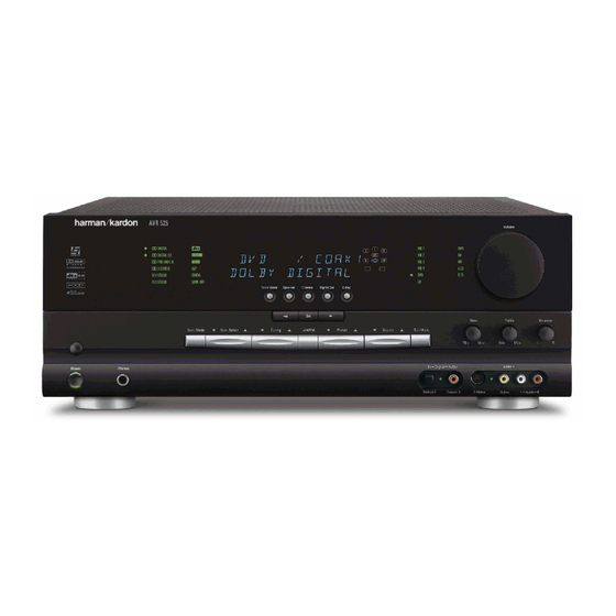
harman/kardon
A/V DOLBY DIGITAL RECEIVER
ESD WARNING......................................2
LEAKAGE TESTING.................................3
BASIC SPECIFICATIONS.........................4
FRONT PANEL CONTROLS.....................5
FRONT PANEL DISPLAY.........................7
REAR PANEL CONNECTIONS..................8
REMOTE CONTROL FUNCTIONS............11
INSTALLATION AND CONNECTIONS.......14
TROUBLESHOOTING GUIDE...................17
PROCESSOR RESET............................17
BLOCK DIAGRAM.................................18
AMPLIFIER BIAS ADJUSTMENT..............19
AVR525
SERVICE MANUAL
250 Crossways Park Dr.
Woodbury, New York 11797
CONTENTS
SERVICE BULLETIN # H/K2003-05.........24
SERVICE BULLETIN # H/K2004-04.........25
TECH TIP HKTT2003-01.......................28
TECH TIP HKTT2004-03.......................29
EXPLODED VIEW...............................33
EXPLODED VIEW PARTS LIST.............34
ELECTRICAL PARTS LIST....................36
PCB DRAWINGS.................................92
SEMICONDUCTOR PINOUTS...............104
SCHEMATICS....................................167
WIRING DIAGRAM..............................186
PACKAGE.........................................187
Rev2 8/2005
Advertisement
Table of Contents

Related Manuals for Harman Kardon AVR525


Summary of Contents for Harman Kardon AVR525
-
Page 1: Table Of Contents
AVR525 A/V DOLBY DIGITAL RECEIVER SERVICE MANUAL CONTENTS ESD WARNING………………………….…….2 SERVICE BULLETIN # H/K2003-05….…..24 SERVICE BULLETIN # H/K2004-04……...25 LEAKAGE TESTING………………..……..3 TECH TIP HKTT2003-01………….……….28 BASIC SPECIFICATIONS…………….….…..4 TECH TIP HKTT2004-03………….……….29 FRONT PANEL CONTROLS………………...5 EXPLODED VIEW………………………….33 FRONT PANEL DISPLAY…………………….7 EXPLODED VIEW PARTS LIST………….34 REAR PANEL CONNECTIONS……..….……8... -
Page 2: Esd Warning
AVR525 Some semiconductor (solid state) devices can be damaged easily by static electricity. Such components commonly are called Electrostatically Sensitive (ES) Devices. Examples of typical ES devices are integrated circuits and some field effect transistors and semiconductor "chip" components. -
Page 3: Leakage Testing
AVR525 Before returning the unit to the user, perform the following safety checks : 1. Inspect all lead dress to make certain that leads are not pinched or that hardware is not lodged between the chassis and other metal parts in the unit. -
Page 4: Basic Specifications
Height measurement includes feet and chassis. Current Capability (HCC) ±45 Amps All features and specifications are subject to change without notice. Transient Intermodulation Harman Kardon and Power for the Digital Revolution are registered trademarks of Distortion (TIM) Unmeasurable Harman International Industries, Incorporated. Slew Rate 40V/µsec... -
Page 5: Front Panel Controls
AVR525 FRONT-PANEL CONTROLS FRONT-PANEL CONTROLS ˘ ˜ ı Ò ¯ ˆ Ú & Ô Ó 1 Main Power Switch Û Delay Adjust Selector Button › 2 System Power Control $ Preset Station Selector Ù Digital Input Selector 3 Power Indicator % Input Source Selector ı... - Page 6 AVR525 FRONT-PANEL CONTROLS Surround Mode Selector 8 to cycle through the Ù Digital Input Selector: Press this button to begin tion on using the tuner.) This button may also be used to switch between Stereo and Mono modes for FM individual modes available.
-
Page 7: Front Panel Display
AVR525 FRONT-PANEL INFORMATION DISPLAY A Upper Display Line F PRESET Indicator K 192kHz Indicator B Lower Display Line G MEMORY Indicator L 96kHz Indicator C OSD Indicator H STEREO Indicator D Multiroom Indicator I TUNED Indicator E Speaker/Channel Input Indicators J AUTO Indicator A Upper Display Line: Depending on the unit’s status,... -
Page 8: Rear Panel Connections
AVR525 REAR-PANEL CONNECTIONS REAR-PANEL CONNECTIONS · ‡ fi ° fl › ¡ £ • ª ‚ ⁄ ‹ ™ ¢ ∞ § ¶ ¡ AM Antenna fi DVD Video Inputs j Multiroom Audio Outputs ™ FM Antenna fl Video 1 Video Inputs k Optical Digital Audio Output £... - Page 9 Connect this jack to the “IR IN” jack on not blocked and that there is at least three inches of Harman Kardon (or other compatible) equipment. fi DVD Video Inputs: Connect the composite or S- open space between the vent holes and any wooden i Coaxial Digital Audio Output: Connect this jack or fabric surface.
- Page 10 AVR525 REAR-PANEL CONNECTIONS Coaxial Digital Audio Inputs: Connect the coax digital output from a DVD player, HDTV receiver, the S/P-DIF output of a compatible computer sound card playing MP3 files or streams, LD player or CD player to these jacks. The signal may be a Dolby Digital signal, DTS signal or a standard PCM digital source.
-
Page 11: Main Remote Control Functions
AVR525 MAIN REMOTE CONTROL FUNCTIONS a Power Off Button b IR Transmitter Window c Program/SPL Indicator d Power On Button e Input Selectors f AVR Selector g AM/FM Tuner Select h 6-Channel/8-Channel Direct Input i Test Button j Sleep Button... - Page 12 AVR 525 and most change a digital input) and then press one of these Harman Kardon CD or DVD players and cassette buttons to scroll through the list of options or to h 6-Channel/8 Channel Direct Input: Press this decks.
- Page 13 AVR525 MAIN REMOTE CONTROL FUNCTIONS MAIN REMOTE CONTROL FUNCTIONS v OSD Button: Press this button to activate the of commands stored in the remote. (See page 39 for SPL Selector: This button activates the more information on storing and recalling macros.) On-Screen Display (OSD) system used to set up or AVR 525’s EzSet function to quickly and accurately...
-
Page 14: Installation And Connections
AVR525 INSTALLATION AND CONNECTIONS 7. Connect the front, center, surround and surround 8. Connections to a subwoofer are normally made via System Installation back speaker outputs §¶ª‚ to the respective a line-level audio connection from the Subwoofer After unpacking the unit, locating it in a place with ade- Output ¢... -
Page 15: System And Power Connections
NOTE: For all options, you may connect an optional IR the Remote IR Input jack on Harman Kardon or other power switch that may be left in the “ON” position. - Page 16 AVR525 INSTALLATION AND CONNECTIONS The AVR 525 features a removable power cord that allows wires to be run to a complex installation so that the unit, itself, need not be installed until it is ready for connection. When all connections described above have been made, connect the AC Power cord to the AC Power Cord Jack ‹.
-
Page 17: Troubleshooting Guide
• Amplifier is in protection mode • Contact your local Harman Kardon service center due to internal problems No sound from surround or • Incorrect surround mode • Select a mode other than Stereo center speakers •... -
Page 19: Amplifier Bias Adjustment
AVR525 AVR325/525 Alignment spec. rev01. 1. MAIN B'D : 5 Min. After power on, please set up Bias as below, Front Left > adjusting VR71, check P801 to 23mV +2mV/- 1mV. Surr Left > adjusting VR73 check P803 to 23mV +2mv/-1mV. - Page 20 AVR525 VR71 FRONT L-CH VR73 SURROUND L-CH P804 FRONT R-CH P802 SURROUND R-CH...
- Page 21 AVR525 VR74 FRONT R-CH VR72 SURROUND R-CH...
- Page 22 AVR525 2. BACK SURROUND B'D : 5 Min. After power on, please set up Bias as below, SBL > adjusting VR31 check P301 to 23mV +2mv/-1mV. Center > adjusting VR41 check P308 to 23mV +2mV/-1mV. SBR > adjusting VR51 check P309 to 23mV +2mV/-1mV.
- Page 23 AVR525 P309 VR51 BACK SURROUND R-CH...
-
Page 24: Service Bulletin # H/K2003-05
Model: AVR325/AVR525 Subject: Software Upgrade A software upgrade is possible for the sub Micro CXP82852-375Q (IC12) in models AVR325 and AVR525; units without the upgrade may exhibit the following symptoms: 1) Dolby Digital EX mode only, Delay adjustment, any speaker size selected: Adjusting the delay time at 14 feet or greater for surround back, surround or center channels, may generate a distortion (like a feedback signal) from the subwoofer output. -
Page 25: Service Bulletin # H/K2004-04
Model: AVR325, AVR525, AVR430, AVR630 Subject: Rewiring Bias/Fan cables In the event you receive an AVR325, AVR525, AVR430 or AVR630 with the complaint: “the unit intermittently goes in standby or the fan runs constantly” perform the following modification. Please note other component or connection failures can cause the unit to go in to standby. - Page 26 AVR525 4) Unplug each the cable on the Bias PCB, desolder the female plugs, cut the connectors off each wire, strip the insulation 1/8” on each end and solder directly to the PCB assembly in each location. 5) For locations N801, N802, N803, N804 on the Main PCB, set the unit on its side and remove the bottom grille.
- Page 27 AVR525 7) Replace the DSP and Processor boards 8) Recheck all bias voltages, following the instructions below: MAIN AMP IDLE CURRENT ADJUSTMENT PROCEDURE (Set variable resistors for MAIN/SURROUND Board) Specialized equipment/parts needed: Variable AC transformer (“Variac” type) to adjust and monitor AC line voltage.
-
Page 28: Tech Tip Hktt2003-01
AVR525 harman/kardon TECH TIPS harman/kardon Troubleshooting tips and solutions to common service problems TIP# HKTT2003-01 Rev5 For models: AVR7000/7200/7300/8000 AVR10 AVR100/200/300/500 DPR1001 AVR110/210/310/510 DPR1005 AVR120/220/320/520 DPR2005 AVR125/225/325/525 HK3370/3470/3375/3475 AVR130/230/330/430/630 HK3250 AVR135/235/335/435/635 Subject: Backup Memory on AVR/DPR/HK series receivers In the event of the complaint: “the receiver is losing its memory (any programmed system settings) when the unit is turned off, or after the unit is unplugged (briefly*)”:... -
Page 29: Tech Tip Hktt2004-03
AVR receiver. Use the following AVR220 AVR320 procedures to help find what is working, then to quickly locate the problem area. AVR520 AVR225 AVR125 AVR525 Equipment needed: AVR130 AVR230 1 set of (RCA) Y adaptors. AVR330 AVR430 Function/signal generator. - Page 30 AVR525 harman/kardon Isolating audio problems in an AVR receiver Using 6/8 Direct In At this point you will be able to check and assure all output levels are the same. 10) IF THE OUTPUT LEVELS ARE NOT THE SAME STOP! Go no further. At this point you will need to use the charts to see where you are losing your signal.
- Page 31 AVR525 harman/kardon Isolating audio problems in an AVR receiver Using 6/8 Direct In AVR,210,310,510 1 15 3 19 17 7 13 27 25 21 20 25 26 10 12 9 24 22 22 23 5 21 19 19 20 8 10...
- Page 32 AVR525 harman/kardon Isolating audio problems in an AVR receiver Using 6/8 Direct In AVR 525 21 22 21 23 7 28 7 29 27 25 26 11 11 26 24 22 23 13 13 8 10 1 13 15 15 23 21...
-
Page 33: Exploded View
AVR525... -
Page 34: Exploded View Parts List
55222010XX CON MAINS INLET A/C INLET 7014-NGP 55206550NR CONN-SPE AC OUTLET 2P 110V FE 12.75MM 2 BK 0 0 55615050 EPR TUNER MODULE KST-M1011MW0-62 AVR525 OEM US/ 55555910XX AC METAL HEATSINK(MAIN) AVR525 -- BLANK 55509110XX FAN RDL8025B C185HS10H1910 ( WIRE:400MM) 0 A0... - Page 35 AVR525 55405680XX AC CPL REAR PANEL AVR525 55554510 AC PLASTIC DUST COVER AVR325/525 67472300NR CONN-SPE 87204-6063 SUB D FE 2.77MM 9 -- 1630 A1 55176390XX CON PHONO SCKT STEREO JACK JW350S 55176420XX AC PUN BRACKET BKT GROUND ET 0.5T AVR520...
-
Page 36: Electrical Parts List
AVR525 AVR525 Electrical Parts List Ref. Part Number Description Designator SURROUND PCB Capacitors CE 470U0F +20% 63.0V 85C C301 13076940AM CE 470U0F +20% 63.0V 85C C302 13076940AM CE 10U0F +20% 50.0V 85C C303 2026888030 CC 270P0F +10% -10% 50.0V Y5P... - Page 37 AVR525 Ref. Part Number Description Designator SURROUND PCB D-SLP 1N4148 100.0V 150E-3A D302 7043654016 D-SLP 1N4148 100.0V 150E-3A D303 7043654016 D-SLP 1N4148 100.0V 150E-3A D304 7043654016 D-SLP 1N4148 100.0V 150E-3A D401 7043654016 D-SLP 1N4148 100.0V 150E-3A D402 7043654016 D-SLP 1N4148 100.0V 150E-3A...
- Page 38 AVR525 Ref. Part Number Description Designator SURROUND PCB TR-SLPLF KTA1024 Y P 50MI0A -150V Q508 5513326056 TR-SLPLF KTC3206 Y N 50MI0A 150V Q509 5513324056 TR-SLPLF KTA1024 Y P 50MI0A -150V Q511 5513326056 TR-SLPLF KTC3206 Y N 50MI0A 150V Q512...
- Page 39 AVR525 Ref. Part Number Description Designator SURROUND PCB RCF 22K0 OHM +5% 250MI0W R344 6044158016 RMOF 10R0 OHM +5% 1.0W R345 6044255016 RCF 100K0 OHM +5% 250MI0W R346 3093951016 RCF 330R0 OHM +5% 250MI0W R401 6044155016 R402 3093949016 RCF 33K0 OHM +5% 250MI0W...
- Page 40 AVR525 Ref. Part Number Description Designator SURROUND PCB RCF 560R0 OHM +5% 250MI0W R511 6044156016 RMF 33K0 OHM +1% 250MI0W R512 5549851016 RMF 1K45 OHM +1% 250MI0W R513 5549850016 RCF 560R0 OHM +5% 250MI0W R514 6044156016 R515 6044156016 RCF 560R0 OHM +5% 250MI0W...
- Page 41 AVR525 Ref. Part Number Description Designator SURROUND PCB CONN 2.5MM 2 MA R NAT 0 0 P309 55104560 CONN 2.0MM 3 MA ST NAT LW2002P03 0 0 P310 55090080 POS 100R0 OHM 16.0V PO51 55179640NR POS 100R0 OHM 16.0V...
- Page 42 AVR525 Ref. Part Number Description Designator DSP PCB CE 10U0F +20% 16.0V 85C C150 1012100039 CE 10U0F +20% 16.0V 85C C151 1012100039 CE 10U0F +20% 16.0V 85C C152 1012100039 CE 10U0F +20% 16.0V 85C C153 1012100039 C154 2050659091 CCCFMIC 100P0F +5% -5% 50.0V NP0 CCCFMIC 100P0F +5% -5% 50.0V NP0...
- Page 43 AVR525 Ref. Part Number Description Designator DSP PCB CCCFMIC 100P0F +5% -5% 50.0V NP0 C206 2050659091 CE 10U0F +20% 16.0V 85C C207 1012100039 CE 100U0F +20% 16.0V 85C C208 1024427039 CE 100U0F +20% 16.0V 85C C209 1024427039 C210 1012100039 CE 10U0F +20% 16.0V 85C...
- Page 44 AVR525 Ref. Part Number Description Designator DSP PCB CE 100U0F +20% 16.0V 85C C263 1024427039 CCCFMIC 100P0F +5% -5% 50.0V NP0 C264 2050659091 CCCFMIC 100N0F +80% -20% 16.0V Y5V C265 2028804091 CCCFMIC 100N0F +80% -20% 16.0V Y5V C266 2028804091 CCCFMIC 100N0F +80% -20% 16.0V Y5V...
- Page 45 IC08 55204160MU IC-LOGIC M74HCU04M1R INVERTER HCT IC09 55133310MT IC-CONV CS5360-KS A/D IC10 55204160MU IC-ASIC M4A3-32-10VC-12VI COMPLEX PLD IC11 55510180MS IC-MICROCONT CXP82852-377Q SUB AVR525 IC12 55519370MS IC-CONV CS5360-KS A/D IC13 55204160MU IC-LOGIC M74HCU04M1R INVERTER HCT IC14 55133310MT IC15 55157760KV IC-EPROM AT27LV040A-90JC...
- Page 46 AVR525 Ref. Part Number Description Designator DSP PCB IC-LOWFREQ CS493263-CL G VERSION DSP IC17 5512538AMU IC-OPERAMP NJM2068M DUAL OP IC18 55142610MT IC-OPERAMP NJM2068M DUAL OP IC19 55142610MT IC-OPERAMP NJM2068M DUAL OP IC20 55142610MT IC-OPERAMP NJM2068M DUAL OP IC21 55142610MT...
- Page 47 AVR525 Ref. Part Number Description Designator DSP PCB RMGCFMIC 560R0 OHM +5% 62MI5W R125 1013493091 RMGCFMIC 10K0 OHM +5% 62MI5W R126 1013501091 RMGCFMIC 10K0 OHM +5% 62MI5W R127 1013501091 RMGCFMIC 1K2 OHM +5% 62MI5W R128 1013579091 RMGCFMIC 1K0 OHM +5% 62MI5W...
- Page 48 AVR525 Ref. Part Number Description Designator DSP PCB RMGCFMIC 10K0 OHM +5% 62MI5W R179 1013501091 RMGCFMIC 10R0 OHM +5% 62MI5W R180 1013441091 RMGCFMIC 5K6 OHM +5% 62MI5W R181 1013596091 RMGCFMIC 5K6 OHM +5% 62MI5W R182 1013596091 RMGCFMIC 5K6 OHM +5% 62MI5W...
- Page 49 AVR525 Ref. Part Number Description Designator DSP PCB RMGCFMIC 150R0 OHM +5% 62MI5W R232 1013478091 RMGCFMIC 1K0 OHM +5% 62MI5W R233 1013577091 RMGCFMIC 47K0 OHM +5% 62MI5W R234 1013522091 RMGCFMIC 1K0 OHM +5% 62MI5W R235 1013577091 RMGCFMIC 20K0 OHM +5% 62MI5W...
- Page 50 AVR525 Ref. Part Number Description Designator DSP PCB RMGCFMIC 150R0 OHM +5% 62MI5W R289 1013478091 RMGCFMIC 10K0 OHM +5% 62MI5W R290 1013501091 RMGCFMIC 150R0 OHM +5% 62MI5W R291 1013478091 RMGCFMIC 10K0 OHM +5% 62MI5W R292 1013501091 RMGCFMIC 10K0 OHM +5% 62MI5W...
- Page 51 AVR525 Ref. Part Number Description Designator DSP PCB RMGCFMIC 10K0 OHM +5% 62MI5W R364 1013501091 RMGCFMIC 220R0 OHM +5% 62MI5W R365 1013483091 RMGCFMIC 4K7 OHM +5% 62MI5W R366 1013594091 RMGCFMIC 100R0 OHM +5% 62MI5W R367 1013474091 RMGCFMIC 10K0 OHM +5% 62MI5W...
- Page 52 AVR525 Ref. Part Number Description Designator DSP PCB RMGCFMIC 3K3 OHM +5% 62MI5W R430 1013590091 RMGCFMIC 10K0 OHM +5% 62MI5W R431 1013501091 RMGCFMIC 10K0 OHM +5% 62MI5W R432 1013501091 RMGCFMIC 3K3 OHM +5% 62MI5W R433 1013590091 RMGCFMIC 10R0 OHM +5% 62MI5W...
- Page 53 AVR525 Ref. Part Number Description Designator DSP PCB CONN 2.0MM 10 MA ST NAT LW2002P10 0 0 P403 55090050 RELAYPWR 5.0V 166.0OHM 1.0A 24.0V SK10 55179930NR TFPULSE TRANSFORMER 110UH FP-120 FERRIT MAGNET T100 55176550NR TFPULSE TRANSFORMER 110UH FP-110 FERRIT MAGNET...
- Page 54 AVR525 Ref. Part Number Description Designator POWER SUPPLY PCB TR-SLPLF MPSA06 N 500MI0A Q102 5514267056 IC-REGPOSFXD KIA7805API TO-220IS NORMAL IC11 55179250MU Resistors RA 3M3 OHM +10% 500MI0W R101 5518010016 RCF 1R0 OHM +5% 250MI0W R102 1106757016 RCF 1R0 OHM +5% 250MI0W...
- Page 55 AVR525 Ref. Part Number Description Designator MAIN PCB CC 100P0F +10% -10% 50.0V Y5P C109 2093665016 CC 100P0F +10% -10% 50.0V Y5P C110 2093665016 CC 100P0F +10% -10% 50.0V Y5P C111 2093665016 CC 100P0F +10% -10% 50.0V Y5P C112 2093665016 CC 100P0F +10% -10% 50.0V Y5P...
- Page 56 AVR525 Ref. Part Number Description Designator MAIN PCB CE 100U0F +20% 25.0V 85C C406 2026907030 CE 220U0F +20% 10.0V 85C C407 2026908030 CE 220U0F +20% 10.0V 85C C408 2026908030 CC 3P0F +0P25F -0P25F 50.0V NP0 C409 2024633071 CC 3P0F +0P25F -0P25F 50.0V NP0...
- Page 57 AVR525 Ref. Part Number Description Designator MAIN PCB CC 10N0F +20% -20% 16.0V Y5S C601 2044901016 CC 10N0F +20% -20% 16.0V Y5S C602 2044901016 Semiconductors D-ZENER MTZJ 12.0V 500MI0W D204 5517804016 D-SLP 1N4148 100.0V 150E-3A D205 7043654016 D-SLP 1N4148 100.0V 150E-3A...
- Page 58 AVR525 Ref. Part Number Description Designator MAIN PCB TR-SLPLF KTA1024 Y P 50MI0A -150V Q316 5513326056 TR-SLPLF KTC3206 Y N 50MI0A 150V Q317 5513324056 TR-SLPLF KTC3206 Y N 50MI0A 150V Q318 5513324056 TR-SLPLF KTA1024 Y P 50MI0A -150V Q319...
- Page 59 AVR525 Ref. Part Number Description Designator MAIN PCB TR-SHPLF 2SA1986-R P -15.0A Q439 551791500 TR-SHPLF 2SA1986-R P -15.0A Q440 551791500 TR-SLPLF KTC3198BL N 150MI0A Q441 2050808056 TR-SLPLF KTA1024 Y P 50MI0A -150V Q442 5513326056 TR-SLPSWA KRC107M N Q443 5517923056...
- Page 60 AVR525 Ref. Part Number Description Designator MAIN PCB RCF 220R0 OHM +5% 250MI0W R317 2046945016 RCF 220R0 OHM +5% 250MI0W R318 2046945016 RCF 220R0 OHM +5% 250MI0W R319 2046945016 RCF 220R0 OHM +5% 250MI0W R320 2046945016 RCF 220R0 OHM +5% 250MI0W...
- Page 61 AVR525 Ref. Part Number Description Designator MAIN PCB RCF 39K0 OHM +5% 250MI0W R383 9057113016 RCF 15K0 OHM +5% 250MI0W R384 5088301016 RCF 15K0 OHM +5% 250MI0W R385 5088301016 RCF 1K5 OHM +5% 250MI0W R386 4043563016 RCF 1K5 OHM +5% 250MI0W...
- Page 62 AVR525 Ref. Part Number Description Designator MAIN PCB RMF 10R0 OHM +5% 500MI0W R447 5523281016 RMF 10R0 OHM +5% 500MI0W R448 5523281016 RCF 100R0 OHM +5% 250MI0W R457 5088295016 RCF 100R0 OHM +5% 250MI0W R458 5088295016 RCF 100R0 OHM +5% 250MI0W...
- Page 63 AVR525 Ref. Part Number Description Designator MAIN PCB RCF 470R0 OHM +5% 250MI0W R594 5088297016 RCF 1K0 OHM +5% 250MI0W R601 1105964016 RCF 100K0 OHM +5% 250MI0W R602 3093951016 RCF 1K0 OHM +5% 250MI0W R603 1105964016 RCF 100K0 OHM +5% 250MI0W...
- Page 64 55135980NR TERMLUG GND TERMLUG GND G102 55135980NR AC HEATSINK REG 118*20*50H AVR520 -- ME HK11 55176400 AC HEATSINK DIODE 39X26X12 AVR525 -- ME HK12 55554410 PROCESSOR PCB Capacitors CCCFMIC 100P0F +5% -5% 50.0V NP0 2050659091 2050659091 CCCFMIC 100P0F +5% -5% 50.0V NP0...
- Page 65 AVR525 Ref. Part Number Description Designator PROCESSOR PCB CE 10U0F +20% 16.0V 85C C123 1500213030 CE 10U0F +20% 16.0V 85C C124 1500213030 CE 10U0F +20% 16.0V 85C C125 1500213030 CE 10U0F +20% 16.0V 85C C126 1500213030 CE 47U0F +20% 16.0V 85C 20251640...
- Page 66 AVR525 Ref. Part Number Description Designator PROCESSOR PCB CE 47U0F +20% 16.0V 85C 20251640 C175 2026783030 CE 1MI0F +20% 6.3V 85C C176 4043309030 CE 1MI0F +20% 6.3V 85C C177 4043309030 CCCFMIC 100P0F +5% -5% 50.0V NP0 C178 2050659091 CCCFMIC 100P0F +5% -5% 50.0V NP0...
- Page 67 AVR525 Ref. Part Number Description Designator PROCESSOR PCB CCCFMIC 100P0F +5% -5% 50.0V NP0 2050659091 CCCFMIC 100P0F +5% -5% 50.0V NP0 2050659091 CCCFMIC 100P0F +5% -5% 50.0V NP0 2050659091 CCCFMIC 100P0F +5% -5% 50.0V NP0 2050659091 CCCFMIC 100P0F +5% -5% 50.0V NP0 2050659091 CCCFMIC 100P0F +5% -5% 50.0V NP0...
- Page 68 AVR525 Ref. Part Number Description Designator PROCESSOR PCB CE 47U0F +20% 16.0V 85C 20251640 2026783030 CE 47U0F +20% 16.0V 85C 20251640 2026783030 CE 47U0F +20% 16.0V 85C 20251640 2026783030 CE 47U0F +20% 16.0V 85C 20251640 2026783030 Semiconductors D-ZENER UDZS 9.1B 9.1V 200MI0W 5550638085 D-ZENER UDZS 9.1B 9.1V 200MI0W...
- Page 69 AVR525 Ref. Part Number Description Designator PROCESSOR PCB TR-SLPSWA KTD1304 N 20V 300MI0A 5513871092 TR-SLPLF MPSA06 N 500MI0A 5514267056 TR-SSD DTA114YKA P 10K0 OHM 47K0 OHM 5513319092 TR-SSD DTA114YKA P 10K0 OHM 47K0 OHM 5513319092 TR-SLPLF KTD1302 B N 300MI0A 20V...
- Page 70 AVR525 Ref. Part Number Description Designator PROCESSOR PCB RMGCFMIC 100K0 OHM +5% 62MI5W R109 1013534091 RMGCFMIC 100R0 OHM +5% 62MI5W 1013474091 RMGCFMIC 100K0 OHM +5% 62MI5W R110 1013534091 RMGCFMIC 100R0 OHM +5% 62MI5W R112 1013474091 RMGCFMIC 100K0 OHM +5% 62MI5W...
- Page 71 AVR525 Ref. Part Number Description Designator PROCESSOR PCB RMGCFMIC 100K0 OHM +5% 62MI5W R161 1013534091 RMGCFMIC 100K0 OHM +5% 62MI5W R162 1013534091 RMGCFMIC 12K0 OHM +5% 62MI5W R163 1013503091 RMGCFMIC 12K0 OHM +5% 62MI5W R164 1013503091 RMGCFMIC 12K0 OHM +5% 62MI5W...
- Page 72 AVR525 Ref. Part Number Description Designator PROCESSOR PCB RMGCFMIC 18K0 OHM +5% 62MI5W R214 1013508091 RMGCFMIC 3K6 OHM +5% 62MI5W R215 1013591091 RMGCFMIC 4K7 OHM +5% 62MI5W R216 1013594091 RMGCFMIC 2K2 OHM +5% 62MI5W R217 1013586091 RMGCFMIC 2K2 OHM +5% 62MI5W...
- Page 73 AVR525 Ref. Part Number Description Designator PROCESSOR PCB RMGCFMIC 1K0 OHM +5% 62MI5W R269 1013577091 RMGCFMIC 470R0 OHM +5% 62MI5W 1013491091 RMGCFMIC 2K0 OHM +5% 62MI5W R270 1013585091 RMGCFMIC 18K0 OHM +5% 62MI5W R271 1013508091 RMGCFMIC 2K2 OHM +5% 62MI5W...
- Page 74 AVR525 Ref. Part Number Description Designator PROCESSOR PCB RMGCFMIC 15K0 OHM +5% 62MI5W R322 1013505091 RMGCFMIC 15K0 OHM +5% 62MI5W R323 1013505091 RMGCFMIC 1K0 OHM +5% 62MI5W R324 1013577091 RMGCFMIC 1K0 OHM +5% 62MI5W R325 1013577091 RMGCFMIC 1K0 OHM +5% 62MI5W...
- Page 75 AVR525 Ref. Part Number Description Designator PROCESSOR PCB RMGCFMIC 100K0 OHM +5% 62MI5W 1013534091 RMGCFMIC 100K0 OHM +5% 62MI5W 1013534091 RMGCFMIC 100K0 OHM +5% 62MI5W 1013534091 RMGCFMIC 100R0 OHM +5% 62MI5W 1013474091 RMGCFMIC 100K0 OHM +5% 62MI5W 1013534091 RMGCFMIC 470R0 OHM +5% 62MI5W...
- Page 76 AVR525 Ref. Part Number Description Designator PROCESSOR PCB Miscellaneous RMGCFMIC 0 OHM +0% 62MI5W 1032875091 RMGCFMIC 0 OHM +0% 62MI5W 1032875091 RMGCFMIC 0 OHM +0% 62MI5W 1032875091 RMGCFMIC 0 OHM +0% 62MI5W 1032875091 RMGCFMIC 0 OHM +0% 62MI5W 1032875091...
- Page 77 AVR525 Ref. Part Number Description Designator VIDEO PCB CCCFMIC 100P0F +5% -5% 50.0V NP0 C114 2050659091 CE 47U0F +20% 16.0V 85C 20251640 C115 2026783030 CE 10U0F +20% 16.0V 85C C116 1500213030 CE 47U0F +20% 16.0V 85C 20251640 C117 2026783030 CCCFMIC 100P0F +5% -5% 50.0V NP0...
- Page 78 AVR525 Ref. Part Number Description Designator VIDEO PCB CC 22P0F +5% -5% 50.0V NP0 C174 8043459071 CC 18P0F +5% -5% 50.0V NP0 C175 4043335071 CE 1U0F +20% 50.0V 85C C176 2026884030 CCCFMIC 33P0F +5% -5% 50.0V NP0 C177 2050656091...
- Page 79 AVR525 Ref. Part Number Description Designator VIDEO PCB D-SLP 1SS355 35.0V 225MI0A D109 2049651085 D-SLP 1SS355 35.0V 225MI0A D110 2049651085 D-SLP 1N4148 100.0V 150E-3A D115 7043654016 IC-SWITCH NJM2296 SOP16 VIDEO IC10 55125370MT IC-SWITCH NJM2296 SOP16 VIDEO IC11 55125370MT IC-SWITCH NJM2296 SOP16 VIDEO...
- Page 80 AVR525 Ref. Part Number Description Designator VIDEO PCB RMGCFMIC 10K0 OHM +5% 62MI5W R124 1013501091 RMGCFMIC 10K0 OHM +5% 62MI5W R125 1013501091 RMGCFMIC 10K0 OHM +5% 62MI5W R126 1013501091 RMGCFMIC 68R0 OHM +5% 62MI5W R127 1013470091 RMGCFMIC 68R0 OHM +5% 62MI5W...
- Page 81 AVR525 Ref. Part Number Description Designator VIDEO PCB RMGCFMIC 0 OHM +0% 62MI5W R184 1032875091 RMGCFMIC 82R0 OHM +5% 62MI5W R185 1013472091 RMGCFMIC 120K0 OHM +5% 62MI5W R186 1013536091 RMGCFMIC 0 OHM +0% 62MI5W R187 1032875091 RMGCFMIC 10K0 OHM +5% 62MI5W...
- Page 82 AVR525 Ref. Part Number Description Designator VIDEO PCB CON DIN SCKT MIX SOCKET RCA-118JP1S NJ93 55149520 CON DIN SCKT MIX SOCKET RCA-118JP1S NJ94 55149520 CON DIN SCKT MIX SOCKET RCA-118JP1S NJ95 55149520 CON DIN SCKT MIX SOCKET RCA-118JP1S NJ96...
- Page 83 AVR525 Ref. Part Number Description Designator KEY PCB RMGCFMIC 2K7 OHM +5% 62MI5W R205 1013588091 RMGCFMIC 3K3 OHM +5% 62MI5W R206 1013590091 RMGCFMIC 5K6 OHM +5% 62MI5W R207 1013596091 RMGCFMIC 8K2 OHM +5% 62MI5W R208 1013600091 RMGCFMIC 18K0 OHM +5% 62MI5W...
- Page 84 AVR525 Ref. Part Number Description Designator KEY PCB FBEAD SURFACE MT 2500OHM FCM2012H-252T02 L102 5512669050 FBEAD SURFACE MT 2500OHM FCM2012H-252T02 L103 5512669050 FBEAD SURFACE MT 2500OHM FCM2012H-252T02 L600 5512669050 FBEAD SURFACE MT 2500OHM FCM2012H-252T02 L601 5512669050 FBEAD SURFACE MT 2500OHM FCM2012H-252T02...
- Page 85 AVR525 Ref. Part Number Description Designator FRONT PCB CE 47U0F +20% 16.0V 85C 20251640 C132 2026783030 CE 47U0F +20% 16.0V 85C 20251640 C133 2026783030 CE 47U0F +20% 16.0V 85C 20251640 C134 2026783030 CPF 47N0F +10% 100.0V C135 1036482071 CPF 47N0F +10% 100.0V...
- Page 86 D-LEM CT-3SGTA GN RND 3.0 CL 60M0CD D751 55199400NR D-LEM CT-3SGTA GN RND 3.0 CL 60M0CD D752 55199400NR D-LEM CT-3SGTA GN RND 3.0 CL 60M0CD D753 55199400NR IC10 55519340MS IC-MICROCONT CXP82860-376Q MAIN AVR525 IC11 20718660MT IC-LOGIC BU4094BF SHIFT REGISTER CMOS...
- Page 87 AVR525 Ref. Part Number Description Designator FRONT PCB IC-LOGIC BU4094BF SHIFT REGISTER CMOS IC12 20718660MT IC-LOGIC BU4094BF SHIFT REGISTER CMOS IC13 20718660MT IC-LOGIC BU4094BF SHIFT REGISTER CMOS IC14 20718660MT IC-LOGIC BU4051BCF MULTIPLEXER HCT IC15 55087180MT PHOTCOUP PC-17T1 PHOTOCOUPLER DIP4...
- Page 88 AVR525 Ref. Part Number Description Designator FRONT PCB RMGCFMIC 220R0 OHM +5% 62MI5W R109 1013483091 RMGCFMIC 1K0 OHM +5% 62MI5W R110 1013577091 RMGCFMIC 470R0 OHM +5% 62MI5W R111 1013491091 RMGCFMIC 470R0 OHM +5% 62MI5W R112 1013491091 RMGCFMIC 390R0 OHM +5% 62MI5W...
- Page 89 AVR525 Ref. Part Number Description Designator FRONT PCB RMGCFMIC 10K0 OHM +5% 62MI5W R173 1013501091 RMGCFMIC 10K0 OHM +5% 62MI5W R174 1013501091 RCF 470R0 OHM +5% 250MI0W R175 5088297016 RMGCFMIC 47K0 OHM +5% 62MI5W R176 1013522091 RMGCFMIC 3K9 OHM +5% 62MI5W...
- Page 90 AVR525 Ref. Part Number Description Designator FRONT PCB RMGCFMIC 150R0 OHM +5% 62MI5W R737 1013478091 RMGCFMIC 150R0 OHM +5% 62MI5W R738 1013478091 RMGCFMIC 150R0 OHM +5% 62MI5W R739 1013478091 RMGCFMIC 150R0 OHM +5% 62MI5W R740 1013478091 RMGCFMIC 150R0 OHM +5% 62MI5W...
- Page 91 CONN 1.25MM 31 FE R BK 00-6216-031-120-808 0 0 DP10 55142780NR DISPLAY HNA-15LL01 FN10 55177570 AC PUN SHIELD FENCE TONE 55505880NR FFC CABLE 25MM 600MM 31 PIN FROM FRONT TO PROC PCB AVR525 COMPLETE TUNER PCB ASS'Y = part# 55615050...
-
Page 92: Pcb Drawings
AVR525... - Page 93 AVR525...
- Page 94 AVR525...
- Page 95 AVR525...
- Page 96 AVR525 harman/kardon...
- Page 97 AVR525...
- Page 98 AVR525...
- Page 99 AVR525...
- Page 100 AVR525...
- Page 101 AVR525...
- Page 102 AVR525...
- Page 103 AVR525...
-
Page 104: Semiconductor Pinouts
AVR525 harman/kardon... - Page 105 AVR525 harman/kardon...
- Page 106 AVR525 harman/kardon...
- Page 107 AVR525 harman/kardon...
- Page 108 AVR525 harman/kardon...
- Page 109 AVR525 harman/kardon CXP82532/82540 CMOS 8-bit Single Chip Microcomputer Description The CXP82532/82540 microcomputer is composed 80 pin QFP (Plastic) of a CPU, ROM RAM, and I/O ports. These chips feature many other high-performance circuits in a single-chip CMOS design, including converter, serial interface, timer/counter, time-base timer, capture timer/counter, fluorescent display controller/driver, remote control receiver.
- Page 110 AVR525 harman/kardon Block Diagram CXP82532/82540 A/D CONVERTER AN0 to AN7 PA0 to PA7 SPC700 CLOCK GEN./ CPU CORE SYSTEM CONTROL T0 to T7 PB0 to PB6 T8/S28 T15/S21 CONTROLLER/ 80 BYTES DRIVER S0 to S20 PC0 to PC7 REMOCON FIFO...
- Page 111 AVR525 harman/kardon CXP82532/82540 Pin Assignment (Top View) 70 69 68 67 PE3/INT3 PE4/RMC T8/S28 T9/S27 PE7/TO T10/S26 PB0/CINT T11/S25 PB1/CS0 T12/S24 PB2/SCK0 T13/S23 T14/S22 PB3/SI0 T15/S21 PB4/SO0 PB5/SCK1 PB6/SI1 PB7/SO1 PC0/KR0 PC1/KR1 PC2/KR2 PF7/S15 PC3/KR3 PF6/S14 PC4/KR4 PF5/S13 PC5/KR5 PF4/S12...
- Page 112 AVR525 harman/kardon CXP82532/82540 Pin Description Symbol Description (Port A) PA0/AN0 8-bit port; single bit Analog input to A/D converter. I/O/Analog input addressable. (8 pins) PA7/AN7 (8 pins) PB0/CINT I/O/Input External capture input for 16-bit timer/counter. PB1/CS0 I/O/Input Chip select input for serial interface (CH0).
- Page 113 AVR525 harman/kardon CXP82532/82540 Symbol Description Provides voltage for FDP when on-chip resistor is selected under mask option. Connection for system clock oscillation crystal. When using an external EXTAL Input clock, input normal signal to EXTAL and reverse phase signal to the...
- Page 114 AVR525 harman/kardon...
- Page 115 AVR525 harman/kardon...
-
Page 116: Package
AVR525 harman/kardon Video Switch · 75Ω driver · Y/C mix MM1501 MITSUMI Video Switch · 75Ω driver · Y/C mix Monolithic IC MM1501 Series Outline This IC extends the series of ICs for video/audio signal switching, with a 2-input 1-output single video switch, video signal/chroma signal 75Ω... - Page 117 AVR525 harman/kardon Video Switch · 75Ω driver · Y/C mix MM1501 MITSUMI Block Diagram MM1501 MM1502 MM1505 MM1506 MM1511 MM1512...
-
Page 118: Absolute Maximum Ratings
AVR525 harman/kardon Video Switch · 75Ω driver · Y/C mix MM1501 MITSUMI Absolute Maximum Ratings (Ta=25°C) Item Symbol Rating Unit -40~+125 °C Storage temperature -30~+75 °C Operating temperature Power supply voltage When alone Allowable loss 350 ( When mounted on board Board size 100mm 100mm t=1.6... - Page 119 AVR525 harman/kardon Video Switch · 75Ω driver · Y/C mix MM1501 MITSUMI MM1503 Item Symbol Measurement conditions Min. Typ. Max. Unit Refer to measurement procedures Consumption current No-signal, no-load 1.80 2.00 2.20 Input pin voltage No-signal, no-load 1.25 Output pin voltage Refer to measurement procedures -0.5...
- Page 120 AVR525 harman/kardon Video Switch · 75Ω driver · Y/C mix MM1501 MITSUMI MM1509 Item Symbol Measurement conditions Min. Typ. Max. Unit Refer to measurement procedures Consumption current Refer to measurement procedures µA Current consumption for PS Refer to measurement procedures...
- Page 121 AVR525 harman/kardon Video Switch · 75Ω driver · Y/C mix MM1501 MITSUMI MM1512 Item Symbol Measurement conditions Min. Typ. Max. Unit Refer to measurement procedures Consumption current No-signal, no-load 1.95 2.15 2.35 Y input pin voltage No-signal, no-load 1.80 2.00 2.20...
- Page 122 AVR525 harman/kardon Video Switch · 75Ω driver · Y/C mix MM1501 MITSUMI ·Measurement Procedures (MM1501 ~ MM1504) Connect a DC ammeter to V pin and measure. Hereafter, short Consumption current the ammeter to use. Input a 2.0V (1.0V for MM1502 and MM1504), 100kHz sine wave to SG1.
- Page 123 AVR525 harman/kardon Video Switch · 75Ω driver · Y/C mix MM1501 MITSUMI · Measurement Procedures (MM1505 ~ MM1508) Connect a DC ammeter to V pin and measure. Hereafter, short Consumption current the ammeter to use. Input a 2.0V (1.0V for MM1506 and MM1508), 100kHz sine wave to SG1.
- Page 124 AVR525 harman/kardon...
- Page 125 AVR525 harman/kardon...
- Page 126 AVR525 harman/kardon...
- Page 127 AVR525 harman/kardon...
- Page 128 AVR525 harman/kardon...
- Page 129 AVR525 harman/kardon...
- Page 130 AVR525 harman/kardon...
- Page 131 AVR525 harman/kardon...
- Page 132 AVR525 harman/kardon...
- Page 133 AVR525 harman/kardon...
- Page 134 AVR525 harman/kardon...
- Page 135 AVR525 harman/kardon 8-channel analog multiplexer / demultiplexer BU4051BC / BU4051BCF / BU4051BCFV The BU4051BC, BU4051BCF and BU4051BCFV are analog multiplexers / demultiplexers which use three-input digi- tal signals for control via an 8-channel analog switch. These products feature high on / off output voltage ratio and low crosstalk between analog switches.
- Page 136 AVR525 harman/kardon Triple 2-channel analog multiplexer / demultiplexer BU4053BC / BU4053BCF / BU4053BCFV The BU4053BC, BU4053BCF, and BU4053BCFV are multiplexers / demultiplexers capable of selecting and combin- ing analog signals and digital signals in a 2 ch × 3 configuration. Inhibit signals and control signals are used to turn on the switch corresponding to each of the channels.
- Page 137 AVR525 harman/kardon...
- Page 138 AVR525 harman/kardon...
- Page 139 AVR525 harman/kardon 8-bit compatible shift / store register BU4094BC / BU4094BCF / BU4094BCFV The BU4094BC, BU4094BCF, and BU4094BCFV are shift / store registers, each consisting of an 8-bit register and an 8-bit latch. As the data in the shift register can be latched by an asynchronous strobe input, it is possible to hold the output in the data transfer mode.
- Page 140 AVR525 harman/kardon...
- Page 141 AVR525 harman/kardon...
- Page 142 AVR525 harman/kardon...
- Page 143 AVR525 harman/kardon...
- Page 144 AVR525 harman/kardon...
- Page 145 AVR525 harman/kardon...
- Page 146 AVR525 harman/kardon...
- Page 147 AVR525 harman/kardon...
- Page 148 AVR525 harman/kardon...
- Page 149 AVR525 harman/kardon...
- Page 150 AVR525 harman/kardon...
- Page 151 AVR525 harman/kardon...
- Page 152 AVR525 harman/kardon...
- Page 153 AVR525 harman/kardon...
- Page 154 AVR525 harman/kardon...
- Page 155 AVR525 harman/kardon M54HCU04 M74HCU04 HEX INVERTER (SINGLE STAGE) HIGH SPEED = 5 ns (TYP.) AT V = 5 V LOW POWER DISSIPATION = 1 µA (MAX.) AT T = 25 C HIGH NOISE IMMUNITY = 10 % V (MIN.) OUTPUT DRIVE CAPABILITY...
- Page 156 AVR525 harman/kardon AK4114 High Feature 192kHz 24bit Digital Audio Interface Transceiver GENERAL DESCRIPTION The AK4114 is a digital audio transceiver supporting 192kHz, 24bits. The channel status decoder supports both consumer and professional modes. The AK4114 can automatically detect a Non-PCM bit stream.
- Page 157 AVR525 harman/kardon AK4114 AVSS AVDD X'tal Clock Oscillator 8 to 3 Recovery Clock MCKO1 Generator MCKO2 Input Selector LRCK DAIF Audio BICK Decoder SDTO DAUX DVDD Error & Q-subcode CCLK DVSS AC-3/MPEG µP I/F STATUS buffer CDTO TVDD Detect Detect...
- Page 158 AVR525 harman/kardon AK4114 PIN/FUNCTION Pin Name Function IPS0 Input Channel Select 0 Pin in Parallel Mode Receiver Channel 4 Pin in Serial Mode (Internal biased pin) No Connect NC(AVSS) No internal bonding. This pin should be connected to AVSS. DIF0...
- Page 159 AVR525 harman/kardon AK4114 PIN/FUNCTION (Continued) Pin Name Function Power-Down Mode Pin When “L”, the AK4114 is powered-down and reset. Master Clock Operation Mode 0 Pin in Parallel Mode CDTO Control Data Output Pin in Serial Mode, IIC= “L”. CAD1 Chip Address 1 Pin in Serial Mode, IIC= “H”.
- Page 160 AVR525 harman/kardon...
- Page 161 AVR525 harman/kardon...
- Page 162 AVR525 harman/kardon...
- Page 163 AVR525 harman/kardon M4A3-32-10VC-12VI...
- Page 164 AVR525 harman/kardon M4A3-32-10VC-12VI...
- Page 165 AVR525 harman/kardon...
- Page 166 AVR525 harman/kardon...
- Page 168 AVR525 harman/kardon...
- Page 171 AVR525 harman/kardon...
- Page 173 AVR525 harman/kardon...
- Page 174 AVR525 harman/kardon...
- Page 175 AVR525 harman/kardon...
- Page 177 AVR525 harman/kardon...
- Page 178 AVR525 harman/kardon...
- Page 180 AVR525 harman/kardon...
- Page 182 AVR525 harman/kardon...
- Page 183 AVR525 harman/kardon...
- Page 184 AVR525 harman/kardon...
- Page 187 AVR525 harman/kardon...