Harman Kardon AVR520 Service Manual
A/v dolby digital receiver
Hide thumbs
Also See for AVR520:
- Service manual (160 pages) ,
- Owner's manual (56 pages) ,
- Product information (2 pages)
Advertisement
Table of Contents
- 1 Table of Contents
- 2 Service Manual
- 3 Technical Specifications
- 4 Front Panel Controls
- 5 Front Panel Information Display
- 6 Rear Panel Connections
- 7 Remote Control Functions
- 8 Main Remote Control Functions
- 9 Troubleshooting Guide
- 10 Processor Reset
- 11 Block Diagram
- 12 Pin Assignment
- 13 Package
- 14 Harman/Kardon, Inc
- Download this manual
See also:
Owner's Manual
harman/kardon
A/V DOLBY DIGITAL RECEIVER
SERVICE MANUAL
ESD WARNING.....................................2
LEAKAGE TESTING...............................3
BASIC SPECIFICATIONS........................4
FRONT PANEL CONTROLS....................5
REAR PANEL CONNECTIONS................10
REMOTE CONTROL FUNCTIONS...........12
TROUBLESHOOTING GUIDE..................15
PROCESSOR RESET............................15
UNIT EXPLODED VIEW..........................16
EXPLODED VIEW PARTS LIST...............17
AVR520
CONTENTS
BLOCK DIAGRAM..................................18
BULLETIN HK2003-07............................19
TECH TIP HKTT2003-01.........................21
TECH TIP HKTT2004-03.........................22
IDLE CURRENT ADJUSTMENT...............26
ELECTRICAL PARTS LIST......................29
SEMICONDUCTOR PINOUTS.................77
SCHEMATICS......................................138
WIRING DIAGRAM................................159
PACKAGE..........................................160
250 Crossways Park Dr.
Woodbury, New York 11797
Rev6 - 2/2009
Advertisement
Table of Contents

Related Manuals for Harman Kardon AVR520


Summary of Contents for Harman Kardon AVR520
-
Page 1: Table Of Contents
AVR520 A/V DOLBY DIGITAL RECEIVER SERVICE MANUAL CONTENTS ESD WARNING…………………..….……….2 BLOCK DIAGRAM..…………..…..……….…18 LEAKAGE TESTING………………...……..3 BULLETIN HK2003-07……….…….………..19 BASIC SPECIFICATIONS……………….…..4 TECH TIP HKTT2003-01……….…….…..…21 FRONT PANEL CONTROLS………….…….5 TECH TIP HKTT2004-03……….…….…..…22 REAR PANEL CONNECTIONS……..…..…10 IDLE CURRENT ADJUSTMENT……………26 REMOTE CONTROL FUNCTIONS………..12 ELECTRICAL PARTS LIST……….…..…….29 TROUBLESHOOTING GUIDE…...……...…15... - Page 2 AVR520 Some semiconductor (solid state) devices can be damaged easily by static electricity. Such components commonly are called Electrostatically Sensitive (ES) Devices. Examples of typical ES devices are integrated circuits and some field effect transistors and semiconductor "chip" components.
- Page 3 AVR520 Before returning the unit to the user, perform the following safety checks : 1. Inspect all lead dress to make certain that leads are not pinched or that hardware is not lodged between the chassis and other metal parts in the unit.
-
Page 4: Technical Specifications
All features and specifications are subject to change without notice. Transient Intermodulation Distortion (TIM) Unmeasurable Harman Kardon is a registered trademark, and Power for the Digital Revolution is a trademark, of Rise Time 16 µsec Harman Kardon, Inc. Slew Rate 40V/µsec... -
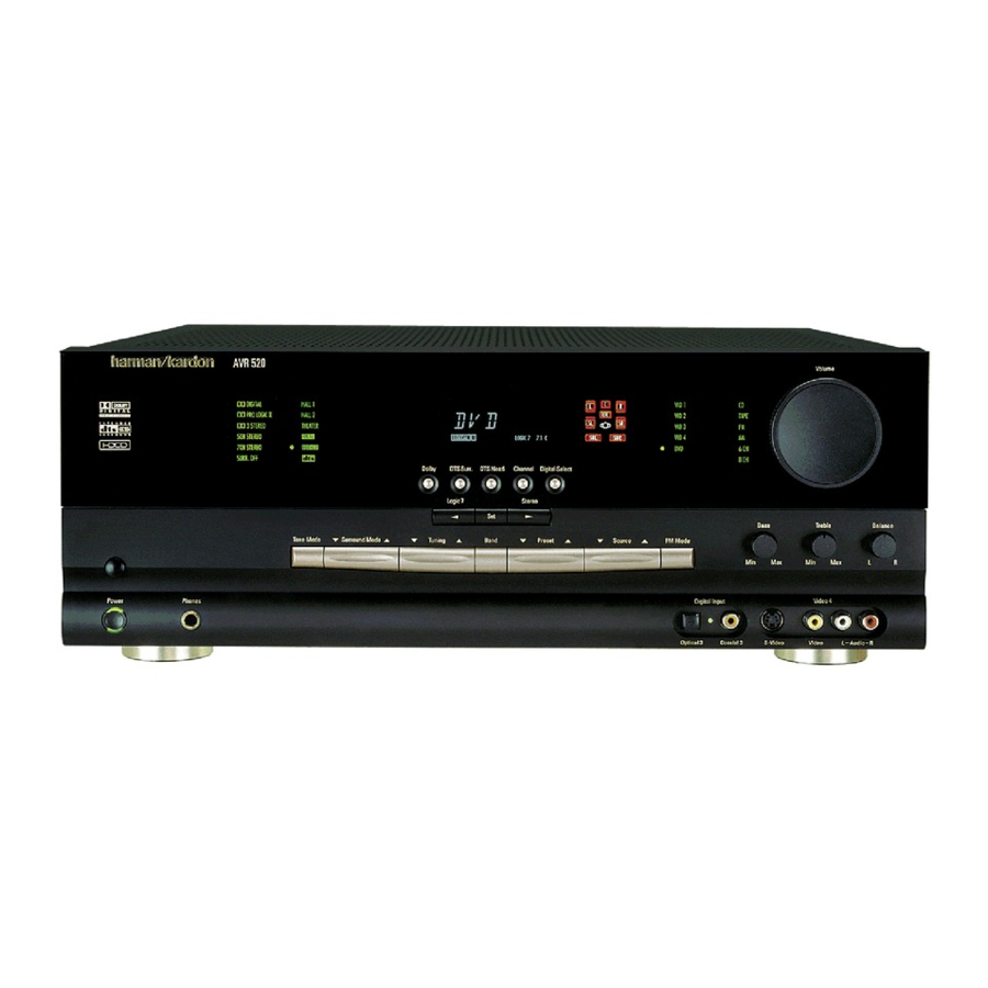
Page 5: Front Panel Controls
AVR520 Front Panel Controls ˘ ¯ ˜ ˆ ı Ù Û Ú Ò Ô & Ó 1 Main Power Switch @ Set Button Ò Balance Control 2 System Power Control # Preset Station Selector Ú Treble Control 3 Power Indicator $ Stereo Mode Selector / Û... - Page 6 AVR520 Front Panel Controls @ Set Button: When making choices during ( Input/Output Status Indicator: These was in use. Each subsequent press selects the next DTS mode in the following order: the setup and configuration process, press this LED indicators will normally light green to show...
- Page 7 AVR520 Front Panel Controls ı Volume Control: Turn this knob clockwise to increase the volume, counterclockwise to decrease the volume. If the AVR 520 is muted, adjusting volume control will automatically release the unit from the silenced condition. ˆ Input Indicators: A green LED will light to the left of the input that is currently the input source for the AVR 520.
-
Page 8: Front Panel Information Display
AVR520 Front Panel Information Display X W V H I J A Bitstream Indicators J Logic 7 Mode Indicators S Preset Indicator B Optical Source Indicators K 5-Channel/7-Channel Stereo Indicators T Sleep Indicator C Sample Rate Indicators L Hall Mode Indicators... - Page 9 AVR520 Front Panel Information Display mation on configuring speakers.) The letters inside each of the center boxes display the active input channels. For standard analog inputs, only the L and R will light, indicating a stereo input. When a...
-
Page 10: Rear Panel Connections
AVR520 Rear Panel Connections · ¡ ™ ° £ › ¢ § • ‚ ¤ fl fi ∞ ¶ ª ⁄ ‹ ‡ ¡ AM Antenna › Front Speaker Outputs h Video 1 Video Inputs ™ FM Antenna fi Center Speaker Outputs i Video 2 Video Outputs £... - Page 11 Connect this jack to that should be connected to the red (+) termi- or other video source. the “IR IN” jack on Harman Kardon (or other nal on speakers with the older color coding. compatible) equipment. Connect the black (–) terminal on the AVR to Video 1 Audio Inputs: Connect these the black negative (–) terminal on your speaker.
-
Page 12: Remote Control Functions
AVR520 Main Remote Control Functions a Power Off Button b IR Transmitter Window c Program/SPL Indicator d Power On Button e Input Selectors f AVR Selector g AM/FM Tuner Select h 6-Channel/8-Channel Direct Input i Test Button j Sleep Button... -
Page 13: Main Remote Control Functions
AVR 520’s remote is shipped from the factory to select the channel being adjusted, then press the choice. Pressing this button when the tuner is operate the AVR 520 and most Harman Kardon Set Button p, followed by the Buttons already in use will select between the AM and ⁄... - Page 14 AVR520 Main Remote Control Functions Buttons n to select the channel you weak will change to monaural reception. (See Skip Up/Down Buttons: These buttons ⁄ ¤ wish to set up. Press the Set Button p and page 31 for more information.) do not have a direct function with the AVR 520, then select another channel to configure.
-
Page 15: Troubleshooting Guide
• Amplifier is in protection mode • Contact your local Harman Kardon service depot due to internal problems No sound from surround or • Incorrect surround mode • Select a mode other than Stereo center speakers •... - Page 16 AVR520 A V R 5 2 0 MODEL P AR TS E XP LOD E D VIE W NAME S C ALE TOLER ANC E LES S ; ± NONE P AR TS S C ALE LES S ; ±...
- Page 17 AVR 5 2 0 EXP LODED VIEW P ART LIS T BLANK To c o m # S Na m e Q' TY 5 5 1 7 7 8 9 0 XX AC CP L REAR P ANEL AVR5 2 0 5 5 1 7 8 0 5 0 XX AC P UN COVER TOP 5 5 1 7 8 3 0 0 XX...
- Page 18 AVR 520Block.sch 1 Thu Mar 21 17:29:13 2002...
- Page 19 AVR520 harman/kardon Service Bulletin Service bulletin # H/K2003-07 Sept. 2003 Warranty labor rate: MINOR repair To: All harman/kardon Service Centers Model: AVR110/210/310/510, AVR120/220; AVR320/520 Subject: Various Complaints For Complaints: NO AUDIO NOISE INTERMITTENT NOISE INTERMITENT AUDIO Possible Solution: Voltages may be too high on DSP Buffer IC or DSP IC All modifications are done to the DSP board.
- Page 20 AVR520 MODELS: AVR110/210/310/510 AVR120/220 MODELS: AVR320/520...
- Page 21 AVR520 harman/kardon TECH TIPS harman/kardon Troubleshooting tips and solutions to common service problems TIP# HKTT2003-01 Rev5 For models: AVR7000/7200/7300/8000 AVR10 AVR100/200/300/500 DPR1001 AVR110/210/310/510 DPR1005 AVR120/220/320/520 DPR2005 AVR125/225/325/525 HK3370/3470/3375/3475 AVR130/230/330/430/630 HK3250 AVR135/235/335/435/635 Subject: Backup Memory on AVR/DPR/HK series receivers In the event of the complaint: “the receiver is losing its memory (any programmed system settings) when the unit is turned off, or after the unit is unplugged (briefly*)”:...
- Page 22 AVR210 AVR310 audio problems in an AVR receiver. Use the following AVR220 AVR320 procedures to help find what is working, then to quickly locate the problem area. AVR520 AVR225 AVR125 AVR525 Equipment needed: AVR130 AVR230 1 set of (RCA) Y adaptors.
- Page 23 AVR520 harman/kardon Isolating audio problems in an AVR receiver Using 6/8 Direct In At this point you will be able to check and assure all output levels are the same. 10) IF THE OUTPUT LEVELS ARE NOT THE SAME STOP! Go no further. At this point you will need to use the charts to see where you are losing your signal.
- Page 24 AVR520 harman/kardon Isolating audio problems in an AVR receiver Using 6/8 Direct In AVR,210,310,510 1 15 3 19 17 7 13 27 25 21 20 25 26 10 12 9 24 22 22 23 5 21 19 19 20 8 10...
- Page 25 AVR520 harman/kardon Isolating audio problems in an AVR receiver Using 6/8 Direct In AVR 525 21 22 21 23 7 28 7 29 27 25 26 11 11 26 24 22 23 13 13 8 10 1 13 15 15 23 21...
- Page 26 AVR520 Idle Adustment Procedure 1. MAIN B'D Turn POWER ON and wait 10 minutes, set controls VR401,VR402,VR501 in order to make voltages on both ends of WA401,WA402,WA403 20mV. See locations below...
- Page 27 AVR520 2. SURROUND B'D Turn POWER ON and wait 10 minutes, set controls VR601,VR602 in order to make voltages on both ends of WA601,WA602 20mV. See locations below...
- Page 28 AVR520...
- Page 29 AVR520 AVR520 Electrical Parts List Main PCB Ref. Part Number Description Designator Capacitors C101 20267830 1 PC CE 47U0F +20% 16.0V 85C C102 20267830 1 PC CE 47U0F +20% 16.0V 85C C103 15002130 1 PC CE 10U0F +20% 16.0V 85C...
- Page 30 AVR520 Ref. Part Number Description Designator C418 55179360 1 PC CPM 100N0F +10% 63.0V C419 55179360 1 PC CPM 100N0F +10% 63.0V C420 55179360 1 PC CPM 100N0F +10% 63.0V C425 11055540 1 PC CC 2N2F +10% -10% 50.0V Y5P...
- Page 31 AVR520 Ref. Part Number Description Designator Semiconductors D401 70436540 1 PC D-SLP 1N4148 100.0V 150E-3A D402 70436540 1 PC D-SLP 1N4148 100.0V 150E-3A D403 70436540 1 PC D-SLP 1N4148 100.0V 150E-3A D404 70436540 1 PC D-SLP 1N4148 100.0V 150E-3A...
- Page 32 AVR520 Ref. Part Number Description Designator Q510 55133240 1 PC TR-SLPLF KTC3206 Y N 50MI0A 150V Q511 55133260 1 PC TR-SLPLF KTA1024 Y P 50MI0A -150V Q512 55133240 1 PC TR-SLPLF KTC3206 Y N 50MI0A 150V Q514 20556600 1 PC...
- Page 33 AVR520 Ref. Part Number Description Designator R110 50882950 1 PC RCF 100R0 OHM +5% 250MI0W R111 50882970 1 PC RCF 470R0 OHM +5% 250MI0W R112 20469460 1 PC RCF 2K2 OHM +5% 250MI0W R113 30939510 1 PC RCF 100K0 OHM +5% 250MI0W...
- Page 34 AVR520 Ref. Part Number Description Designator R434 50882960 1 PC RCF 150R0 OHM +5% 250MI0W R435 50882960 1 PC RCF 150R0 OHM +5% 250MI0W R436 50882960 1 PC RCF 150R0 OHM +5% 250MI0W R437 50883010 1 PC RCF 15K0 OHM +5% 250MI0W...
- Page 35 AVR520 Ref. Part Number Description Designator R512 60441560 1 PC RCF 560R0 OHM +5% 250MI0W R513 60441560 1 PC RCF 560R0 OHM +5% 250MI0W R514 60441560 1 PC RCF 560R0 OHM +5% 250MI0W R515 60441560 1 PC RCF 560R0 OHM +5% 250MI0W...
- Page 36 CONN 2.0MM 9 MA ST NAT MOLEX 35336-0910 0 0 CP401 55182570 1 PC WIRECONASY UNIQUE 7P 240MM UL1533 SHIELD 28 1 55176400 1 PC AC HEATSINK REG 118*20*50H AVR520 -- ME FU481 20828790 1 PC FUSULSLWBL 2.0 A 250.0 V FU482 20828790 1 PC FUSULSLWBL 2.0 A 250.0 V...
- Page 37 AVR520 Ref. Part Number Description Designator FH401 55170330 1 PC TERMFUSEHLDR FUSE-HOLDER J4210020001X FH402 55170330 1 PC TERMFUSEHLDR FUSE-HOLDER J4210020001X FH403 55170330 1 PC TERMFUSEHLDR FUSE-HOLDER J4210020001X FH404 55170330 1 PC TERMFUSEHLDR FUSE-HOLDER J4210020001X FH405 55170330 1 PC TERMFUSEHLDR FUSE-HOLDER J4210020001X...
- Page 38 AVR520 Ref. Part Number Description Designator C136 20268880 1 PC CE 10U0F +20% 50.0V 85C C137 20267830 1 PC CE 47U0F +20% 16.0V 85C C138 20267830 1 PC CE 47U0F +20% 16.0V 85C Semiconductors IC101 55142710 1 PC IC-SWITCH KIC9162AF ANALOG SWITCH...
- Page 39 AVR520 Ref. Part Number Description Designator R131 30939510 1 PC RCF 100K0 OHM +5% 250MI0W R132 50882970 1 PC RCF 470R0 OHM +5% 250MI0W R133 50882950 1 PC RCF 100R0 OHM +5% 250MI0W R134 50882950 1 PC RCF 100R0 OHM +5% 250MI0W...
- Page 40 AVR520 Ref. Part Number Description Designator C374 20267830 1 PC CE 47U0F +20% 16.0V 85C C375 20267830 1 PC CE 47U0F +20% 16.0V 85C C386 20246470 1 PC CC 100N0F +80% -20% 25.0V Z5V C601 20268880 1 PC CE 10U0F +20% 50.0V 85C...
- Page 41 AVR520 Ref. Part Number Description Designator CA81 55095460 1 PC CPPMX 100N0F +20% -20% Semiconductors D601 70436540 1 PC D-SLP 1N4148 100.0V 150E-3A D602 70436540 1 PC D-SLP 1N4148 100.0V 150E-3A D603 70436540 1 PC D-SLP 1N4148 100.0V 150E-3A...
- Page 42 AVR520 Ref. Part Number Description Designator D984 20415060 1 PC D-SR 1N4004 400.0V 1.0A D985 20415060 1 PC D-SR 1N4004 400.0V 1.0A D986 20415060 1 PC D-SR 1N4004 400.0V 1.0A D989 20415060 1 PC D-SR 1N4004 400.0V 1.0A D990...
- Page 43 AVR520 Ref. Part Number Description Designator R612 20469450 1 PC RCF 220R0 OHM +5% 250MI0W R613 11059610 1 PC RCF 270R0 OHM +5% 250MI0W R614 11059610 1 PC RCF 270R0 OHM +5% 250MI0W R615 20469510 1 PC RCF 43K0 OHM +5% 250MI0W...
- Page 44 1 PC CONN-SPE AC OUTLET 2P 110V FE 12.75MM 2 BK 0 0 BKT1 55176420 1 PC AC PUN BRACKET BKT GROUND ET 0.5T AVR520 -- BKT2 55176420 1 PC AC PUN BRACKET BKT GROUND ET 0.5T AVR520 -- C378...
- Page 45 AVR520 Ref. Part Number Description Designator H020 55180170 1 PC WIRECONASY UNIQUE 1P 200MM UL1007 PVC DISCRETE 18 1 JA290 55176360 1 PC CON PHONO SCKT RCA 9P W/GNDCAP JK090122LN JK601 55191390 1 PC CONN-SPE TERMINAL SPKR 4P SH0410376P FE 19MM 4 BK 0 0...
- Page 46 AVR520 Ref. Part Number Description Designator C235 10364820 1 PC CPF 47N0F +10% 100.0V C236 10364820 1 PC CPF 47N0F +10% 100.0V CL201 15002130 1 PC CE 10U0F +20% 16.0V 85C CL202 30936230 1 PC CC 100P0F +5% -5% 50.0V NP0...
- Page 47 AVR520 Ref. Part Number Description Designator Q220 55133330 1 PC TR-SSD DTC114TKA N 10K0 OHM Q221 55133330 1 PC TR-SSD DTC114TKA N 10K0 OHM Q228 55133180 1 PC TR-SSD DTC114YKA N 10K0 OHM 47K0 OHM Q229 55133180 1 PC...
- Page 48 1 PC D-LEM CT-3SGTA GN RND 3.0 CL 60M0CD D268 55199400 1 PC D-LEM CT-3SGTA GN RND 3.0 CL 60M0CD IC201 5518246CMS 1 PC IC-MICROCONT CXP82860-353Q MAIN AVR520 IC205 55142240 1 PC IC-OPERAMP NJM2068DD DUAL OP Resistors R201 80440370 1 PC...
- Page 49 AVR520 Ref. Part Number Description Designator R231 80440370 1 PC RMGCFMIN 150R0 OHM +5% 100MI0W R232 80440370 1 PC RMGCFMIN 150R0 OHM +5% 100MI0W R233 80440370 1 PC RMGCFMIN 150R0 OHM +5% 100MI0W R234 80440370 1 PC RMGCFMIN 150R0 OHM +5% 100MI0W...
- Page 50 AVR520 Ref. Part Number Description Designator R292 50886630 1 PC RMGCFMIN 100K0 OHM +5% 100MI0W R293 11066460 1 PC RMGCFMIN 8K2 OHM +5% 100MI0W R294 50886610 1 PC RMGCFMIN 10K0 OHM +5% 100MI0W R295 20471950 1 PC RMGCFMIN 1K0 OHM +5% 100MI0W...
- Page 51 AVR520 Ref. Part Number Description Designator RR204 11066480 1 PC RMGCFMIN 47K0 OHM +5% 100MI0W RR205 90574400 1 PC RMGCFMIN 470R0 OHM +5% 100MI0W RR206 50886630 1 PC RMGCFMIN 100K0 OHM +5% 100MI0W RR207 20471940 1 PC RMGCFMIN 680R0 OHM +5% 100MI0W...
- Page 52 AVR520 Ref. Part Number Description Designator CP202 55182560 1 PC WIRECONASY UNIQUE 5P 300MM UL1007 PVC DISCRETE 26 1 CP203 55123340 1 PC CONN 2.0MM 8 MA ST NAT LW2002P08 0 0 CP204 55123320 1 PC CONN 2.0MM 5 MA ST NAT LW2002P05 0 0...
- Page 53 AVR520 Ref. Part Number Description Designator R406 50886590 1 PC RMGCFMIN 2K7 OHM +5% 100MI0W R407 11066440 1 PC RMGCFMIN 3K3 OHM +5% 100MI0W R408 80440400 1 PC RMGCFMIN 5K6 OHM +5% 100MI0W R409 11066460 1 PC RMGCFMIN 8K2 OHM +5% 100MI0W...
- Page 54 55123310 1 PC CONN 2.0MM 4 MA ST NAT LW2002P04 0 0 FN401 55176420 1 PC AC PUN BRACKET BKT GROUND ET 0.5T AVR520 -- FN402 55176420 1 PC AC PUN BRACKET BKT GROUND ET 0.5T AVR520 -- HP401 55088400 1 PC CONN-PHJAC 6.35 ST HORZ EST-J6313 BK 0 0...
- Page 55 AVR520 Ref. Part Number Description Designator C177 10138390 1 PC CCCFMIC 560P0F +10% -10% 50.0V X7R C178 10138550 1 PC CCCFMIC 1N0F +10% -10% 50.0V X7R C178 11059320 1 PC CCCFMIN 1N0F +10% -10% 50.0V X7R C179 10138390 1 PC CCCFMIC 560P0F +10% -10% 50.0V X7R...
- Page 56 AVR520 Ref. Part Number Description Designator C157 20288040 1 PC CCCFMIC 100N0F +80% -20% 16.0V Y5V C158 20288040 1 PC CCCFMIC 100N0F +80% -20% 16.0V Y5V C159 20288040 1 PC CCCFMIC 100N0F +80% -20% 16.0V Y5V C168 20288040 1 PC CCCFMIC 100N0F +80% -20% 16.0V Y5V...
- Page 57 AVR520 Ref. Part Number Description Designator C525 10121000 1 PC CE 10U0F +20% 16.0V 85C C526 10121000 1 PC CE 10U0F +20% 16.0V 85C C527 10121000 1 PC CE 10U0F +20% 16.0V 85C C528 10121000 1 PC CE 10U0F +20% 16.0V 85C...
- Page 58 1 PC IC-SWITCH NJU201AM ANALOG SWITCH IC127 55180060 1 PC IC-SPECFUNC NJU6324M SOP8 CMOS-CRYSTAL IC128 5518247B 1 PC IC-MICROCONT CXP82532-197Q SUB AVR520 IC129 55182540 1 PC IC-REGPOSFXD 2.7V MM1562H NORMAL Q101 55133330 1 PC TR-SSD DTC114TKA N 10K0 OHM Resistors...
- Page 59 AVR520 Ref. Part Number Description Designator R139 10135770 1 PC RMGCFMIC 1K0 OHM +5% 62MI5W R140 10134740 1 PC RMGCFMIC 100R0 OHM +5% 62MI5W R142 10135860 1 PC RMGCFMIC 2K2 OHM +5% 62MI5W R143 10135220 1 PC RMGCFMIC 47K0 OHM +5% 62MI5W...
- Page 60 AVR520 Ref. Part Number Description Designator R199 10135960 1 PC RMGCFMIC 5K6 OHM +5% 62MI5W R200 10135790 1 PC RMGCFMIC 1K2 OHM +5% 62MI5W R201 10135790 1 PC RMGCFMIC 1K2 OHM +5% 62MI5W R202 10135960 1 PC RMGCFMIC 5K6 OHM +5% 62MI5W...
- Page 61 AVR520 Ref. Part Number Description Designator R257 10135010 1 PC RMGCFMIC 10K0 OHM +5% 62MI5W R258 10135010 1 PC RMGCFMIC 10K0 OHM +5% 62MI5W R259 10135010 1 PC RMGCFMIC 10K0 OHM +5% 62MI5W R260 10135090 1 PC RMGCFMIC 20K0 OHM +5% 62MI5W...
- Page 62 AVR520 Ref. Part Number Description Designator BD16 55126690 1 PC FBEAD SURFACE MT 2500OHM FCM2012H-252T02 BD17 55126690 1 PC FBEAD SURFACE MT 2500OHM FCM2012H-252T02 BD20 55126650 1 PC FBEAD SURFACE MT 300OHM FCM2012V-301T07 BD21 55126650 1 PC FBEAD SURFACE MT 300OHM FCM2012V-301T07...
- Page 63 AVR520 Ref. Part Number Description Designator C642 11058670 1 PC CCCFMIN 100P0F +5% -5% 50.0V NP0 C657 20267290 1 PC CCCFMIN 100N0F +80% -20% 50.0V Y5V C658 11058670 1 PC CCCFMIN 100P0F +5% -5% 50.0V NP0 C659 11058670 1 PC CCCFMIN 100P0F +5% -5% 50.0V NP0...
- Page 64 AVR520 Ref. Part Number Description Designator C663 40433090 1 PC CE 1MI0F +20% 6.3V 85C C664 20252670 1 PC CE 470U0F +20% 10.0V 85C C665 20252670 1 PC CE 470U0F +20% 10.0V 85C C666 20269080 1 PC CE 220U0F +20% 10.0V 85C...
- Page 65 AVR520 Ref. Part Number Description Designator Q603 55157120 1 PC TR-SLPLF KTC2874 A N 300MI0A 20V Q604 55157120 1 PC TR-SLPLF KTC2874 A N 300MI0A 20V Q605 55101930 1 PC TR-SLPLF 2SA933ASR P -3.0A -20V Q609 55157120 1 PC...
- Page 66 AVR520 Ref. Part Number Description Designator R678 20471950 1 PC RMGCFMIN 1K0 OHM +5% 100MI0W R679 20471950 1 PC RMGCFMIN 1K0 OHM +5% 100MI0W R680 40438300 1 PC RMGCFMIN 6K8 OHM +5% 100MI0W R681 80440390 1 PC RMGCFMIN 2K2 OHM +5% 100MI0W...
- Page 67 AVR520 Ref. Part Number Description Designator R640 20469460 1 PC RCF 2K2 OHM +5% 250MI0W R674 11059640 1 PC RCF 1K0 OHM +5% 250MI0W R686 50883030 1 PC RCF 150K0 OHM +5% 250MI0W R695 60441550 1 PC RCF 330R0 OHM +5% 250MI0W...
- Page 68 AVR520 Ref. Part Number Description Designator Process PCB Capacitors C701 11058670 1 PC CCCFMIN 100P0F +5% -5% 50.0V NP0 C702 11058670 1 PC CCCFMIN 100P0F +5% -5% 50.0V NP0 C703 11058670 1 PC CCCFMIN 100P0F +5% -5% 50.0V NP0...
- Page 69 AVR520 Ref. Part Number Description Designator C863 80436820 1 PC CCCFMIN 680P0F +10% -10% 50.0V X7R C865 80436820 1 PC CCCFMIN 680P0F +10% -10% 50.0V X7R C868 11058670 1 PC CCCFMIN 100P0F +5% -5% 50.0V NP0 C869 11058670 1 PC CCCFMIN 100P0F +5% -5% 50.0V NP0...
- Page 70 AVR520 Ref. Part Number Description Designator C797 20267830 1 PC CE 47U0F +20% 16.0V 85C C798 20267830 1 PC CE 47U0F +20% 16.0V 85C C799 20267830 1 PC CE 47U0F +20% 16.0V 85C C800 10121000 1 PC CE 10U0F +20% 16.0V 85C...
- Page 71 AVR520 Ref. Part Number Description Designator IC710 55142610 1 PC IC-OPERAMP NJM2068M DUAL OP IC711 55142610 1 PC IC-OPERAMP NJM2068M DUAL OP IC712 55142610 1 PC IC-OPERAMP NJM2068M DUAL OP IC713 55142610 1 PC IC-OPERAMP NJM2068M DUAL OP IC714...
- Page 72 AVR520 Ref. Part Number Description Designator R706 40438350 1 PC RMGCFMIN 470K0 OHM +5% 100MI0W R707 90574400 1 PC RMGCFMIN 470R0 OHM +5% 100MI0W R708 40438350 1 PC RMGCFMIN 470K0 OHM +5% 100MI0W R709 70434200 1 PC RMGCFMIN 100R0 OHM +5% 100MI0W...
- Page 73 AVR520 Ref. Part Number Description Designator R764 50886630 1 PC RMGCFMIN 100K0 OHM +5% 100MI0W R765 70434200 1 PC RMGCFMIN 100R0 OHM +5% 100MI0W R766 80440390 1 PC RMGCFMIN 2K2 OHM +5% 100MI0W R767 80440390 1 PC RMGCFMIN 2K2 OHM +5% 100MI0W...
- Page 74 AVR520 Ref. Part Number Description Designator R822 80440390 1 PC RMGCFMIN 2K2 OHM +5% 100MI0W R823 30944340 1 PC RMGCFMIN 27K0 OHM +5% 100MI0W R830 11066480 1 PC RMGCFMIN 47K0 OHM +5% 100MI0W R831 90574400 1 PC RMGCFMIN 470R0 OHM +5% 100MI0W...
- Page 75 AVR520 Ref. Part Number Description Designator R886 20472020 1 PC RMGCFMIN 180K0 OHM +5% 100MI0W R887 50886630 1 PC RMGCFMIN 100K0 OHM +5% 100MI0W R888 90574400 1 PC RMGCFMIN 470R0 OHM +5% 100MI0W R889 20472020 1 PC RMGCFMIN 180K0 OHM +5% 100MI0W...
- Page 76 55088230 1 PC CON PHONO SCKT RCA-606P 6 PINS JK702 55176330 1 PC CON PHONO SCKT RCA 4P JW4104RS GND JK703 55176330 1 PC CON PHONO SCKT RCA 4P JW4104RS GND THE AVR520 TUNER IS A NON-SERVICEABLE MODULE - PART#55177300XX...
- Page 77 AVR520 harman/kardon...
- Page 78 AVR520 harman/kardon...
- Page 79 AVR520 harman/kardon...
- Page 80 AVR520 harman/kardon...
- Page 81 AVR520 harman/kardon...
- Page 82 AVR520 harman/kardon CXP82532/82540 CMOS 8-bit Single Chip Microcomputer Description The CXP82532/82540 microcomputer is composed 80 pin QFP (Plastic) of a CPU, ROM RAM, and I/O ports. These chips feature many other high-performance circuits in a single-chip CMOS design, including converter, serial interface, timer/counter, time-base timer, capture timer/counter, fluorescent display controller/driver, remote control receiver.
- Page 83 AVR520 harman/kardon Block Diagram CXP82532/82540 A/D CONVERTER AN0 to AN7 PA0 to PA7 SPC700 CLOCK GEN./ CPU CORE SYSTEM CONTROL T0 to T7 PB0 to PB6 T8/S28 T15/S21 CONTROLLER/ 80 BYTES DRIVER S0 to S20 PC0 to PC7 REMOCON FIFO...
- Page 84 AVR520 harman/kardon CXP82532/82540 Pin Assignment (Top View) 70 69 68 67 PE3/INT3 PE4/RMC T8/S28 T9/S27 PE7/TO T10/S26 PB0/CINT T11/S25 PB1/CS0 T12/S24 PB2/SCK0 T13/S23 T14/S22 PB3/SI0 T15/S21 PB4/SO0 PB5/SCK1 PB6/SI1 PB7/SO1 PC0/KR0 PC1/KR1 PC2/KR2 PF7/S15 PC3/KR3 PF6/S14 PC4/KR4 PF5/S13 PC5/KR5 PF4/S12...
- Page 85 AVR520 harman/kardon CXP82532/82540 Pin Description Symbol Description (Port A) PA0/AN0 8-bit port; single bit Analog input to A/D converter. I/O/Analog input addressable. (8 pins) PA7/AN7 (8 pins) PB0/CINT I/O/Input External capture input for 16-bit timer/counter. PB1/CS0 I/O/Input Chip select input for serial interface (CH0).
- Page 86 AVR520 harman/kardon CXP82532/82540 Symbol Description Provides voltage for FDP when on-chip resistor is selected under mask option. Connection for system clock oscillation crystal. When using an external EXTAL Input clock, input normal signal to EXTAL and reverse phase signal to the...
- Page 87 AVR520 harman/kardon...
- Page 88 AVR520 harman/kardon...
- Page 89 AVR520 harman/kardon...
- Page 90 AVR520 harman/kardon...
- Page 91 AVR520 harman/kardon...
- Page 92 AVR520 harman/kardon...
- Page 93 AVR520 harman/kardon...
- Page 94 AVR520 harman/kardon...
- Page 95 AVR520 harman/kardon...
-
Page 96: Block Diagram
AVR520 harman/kardon 8-channel analog multiplexer / demultiplexer BU4051BC / BU4051BCF / BU4051BCFV The BU4051BC, BU4051BCF and BU4051BCFV are analog multiplexers / demultiplexers which use three-input digi- tal signals for control via an 8-channel analog switch. These products feature high on / off output voltage ratio and low crosstalk between analog switches. - Page 97 AVR520 harman/kardon 8-bit compatible shift / store register BU4094BC / BU4094BCF / BU4094BCFV The BU4094BC, BU4094BCF, and BU4094BCFV are shift / store registers, each consisting of an 8-bit register and an 8-bit latch. As the data in the shift register can be latched by an asynchronous strobe input, it is possible to hold the output in the data transfer mode.
- Page 98 AVR520 harman/kardon...
- Page 99 AVR520 harman/kardon...
- Page 100 AVR520 harman/kardon...
- Page 101 AVR520 harman/kardon...
- Page 102 AVR520 harman/kardon...
- Page 103 AVR520 harman/kardon...
- Page 104 AVR520 harman/kardon...
- Page 105 AVR520 harman/kardon...
-
Page 106: Package
AVR520 harman/kardon MITSUMI 500mA Regulator MM156 500mA Regulator Monolithic IC MM156 Outline This IC is a small, stable power supply with output voltage precision of ±2% (when I = 250mA), maximum output current of 500mA, and I/O voltage difference of 0.3V typ. at 250mA. - Page 107 AVR520 harman/kardon...
- Page 108 AVR520 harman/kardon...
- Page 109 AVR520 harman/kardon...
- Page 110 AVR520 harman/kardon...
- Page 111 AVR520 harman/kardon...
- Page 112 AVR520 harman/kardon...
- Page 113 AVR520 harman/kardon...
- Page 114 AVR520 harman/kardon...
- Page 115 AVR520 harman/kardon...
- Page 116 AVR520 harman/kardon...
- Page 117 AVR520 harman/kardon Triple 2-channel analog multiplexer / demultiplexer BU4053BC / BU4053BCF / BU4053BCFV The BU4053BC, BU4053BCF, and BU4053BCFV are multiplexers / demultiplexers capable of selecting and combin- ing analog signals and digital signals in a 2 ch 3 configuration. Inhibit signals and control signals are used to turn on the switch corresponding to each of the channels.
- Page 118 AVR520 harman/kardon...
- Page 119 AVR520 harman/kardon...
- Page 120 AVR520 harman/kardon...
- Page 121 AVR520 harman/kardon...
- Page 122 AVR520 harman/kardon...
- Page 123 AVR520 harman/kardon...
- Page 124 AVR520 harman/kardon...
- Page 125 AVR520 harman/kardon...
- Page 126 AVR520 harman/kardon...
- Page 127 AVR520 harman/kardon...
- Page 128 AVR520 harman/kardon...
- Page 129 AVR520 harman/kardon...
- Page 130 AVR520 harman/kardon...
- Page 131 AVR520 harman/kardon...
- Page 132 AVR520 harman/kardon...
- Page 133 AVR520 harman/kardon...
- Page 134 AVR520 harman/kardon...
- Page 135 AVR520 harman/kardon...
- Page 136 AVR520 harman/kardon...
- Page 137 AVR520 harman/kardon...
- Page 138 R520VIDEO MP.sch 1 Thu Mar 21 17:41:04 2002...
- Page 139 R520VIDEO MP.sch 1 Thu Mar 21 17:41:04 2002...
- Page 142 AVR520 harman/kardon...
- Page 145 AVR520 harman/kardon...
- Page 146 AVR520 harman/kardon...
- Page 149 AVR520 harman/kardon...
- Page 160 BE10B00...