Table of Contents
Advertisement
Universal Air Conditioner
SVC MANUAL(Exploded View)
MODEL : LAN126HNP(ASNH121F2G1) LAU126HNP(ASUH121FUG1)
LAN096HNP(ASNH091F2G1) LAU096HNP(ASUH091FUG1)
LAN091CNP (ASNC091F2G0) LAU091CNP (ASUC091FUG0)
LAN121CNP (ASNC121F2G0) LAU121CNP (ASUC121FUG0)
LAN091HNP (ASNH091F2G0) LAU091HNP (ASUH091FUG0)
LAN121HNP (ASNH121F2G0) LAU121HNP (ASUH121FUG0)
LA090CPI (ASNC091F2G0)
LA120CPI (ASNC091F2G0)
LA090HPI (ASNH091F2G0)
LA120HPI (ASNH121F2G0)
CAUTION
Before Servicing the unit, read the safety precautions in General SVC manual.
Only for authorized service personnel.
Internal Use Only
http://biz.lgservice.com
LA090CPO (ASUC091FUG0)
LA120CPO (ASUC091FUG0)
LA090HPO (ASUH091FUG0)
LA120HPO (ASUH121FUG0)
Advertisement
Table of Contents

Related Manuals for LG LAN126HNP


Summary of Contents for LG LAN126HNP
- Page 1 Internal Use Only http://biz.lgservice.com Universal Air Conditioner SVC MANUAL(Exploded View) MODEL : LAN126HNP(ASNH121F2G1) LAU126HNP(ASUH121FUG1) LAN096HNP(ASNH091F2G1) LAU096HNP(ASUH091FUG1) LAN091CNP (ASNC091F2G0) LAU091CNP (ASUC091FUG0) LAN121CNP (ASNC121F2G0) LAU121CNP (ASUC121FUG0) LAN091HNP (ASNH091F2G0) LAU091HNP (ASUH091FUG0) LAN121HNP (ASNH121F2G0) LAU121HNP (ASUH121FUG0) LA090CPI (ASNC091F2G0) LA090CPO (ASUC091FUG0) LA120CPI (ASNC091F2G0) LA120CPO (ASUC091FUG0)
-
Page 2: Table Of Contents
Refrigeration Cycle Diagram.............................55 Pipe length and the elevation ...........................56 3-way Valve ................................57 Cycle Parts ................................63 Electronic Parts.................................64 Exploded View ................................73 - 2 - Copyright ©2010 LG Electronics. Inc. All right reserved. LGE Internal Use Only Only for training and service purposes... -
Page 3: Safety Precautions
• There is risk of fire or electric • There is risk of fire, electric shock, shock. shock. explosion, or injury. - 3 - Copyright ©2010 LG Electronics. Inc. All right reserved. LGE Internal Use Only Only for training and service purposes... - Page 4 • There is risk of fire or electrical shock. • There is risk of fire or electric shock. shock. - 4 - Copyright ©2010 LG Electronics. Inc. All right reserved. LGE Internal Use Only Only for training and service purposes...
- Page 5 • There is risk of electrical shock or • There is risk of property damage, fire failure of product, or electric shock. - 5 - Copyright ©2010 LG Electronics. Inc. All right reserved. LGE Internal Use Only Only for training and service purposes...
- Page 6 • A bad connection may cause water • To avoid vibration or water leakage. failure of product. leakage. 90˚ - 6 - Copyright ©2010 LG Electronics. Inc. All right reserved. LGE Internal Use Only Only for training and service purposes...
- Page 7 • There is risk of personal injury and or damage to the plastic parts of failure of product. the product. - 7 - Copyright ©2010 LG Electronics. Inc. All right reserved. LGE Internal Use Only Only for training and service purposes...
- Page 8 • They may burn or explode. • The chemicals in batteries could cause burns or other health hazards. - 8 - Copyright ©2010 LG Electronics. Inc. All right reserved. LGE Internal Use Only Only for training and service purposes...
-
Page 9: Dimensions
This symbol indicates special notes. Indoor Unit Hanger Hole Fix Hole Pipe Hole Model INDOOR UNIT Dimension mm(inch) 600(23.6) mm(inch) 600(23.6) mm(inch) 146(5.7) - 9 - Copyright ©2010 LG Electronics. Inc. All right reserved. LGE Internal Use Only Only for training and service purposes... -
Page 10: Outdoor Unit
(3-way valve) Liquid side (2-way valve) MODEL 9k, 12k Models unit 770(30.3) 540(21.3) 245(9.6) 285(11.2) 64(2.5) 518(20.4) 10(0.4) 100(3.9) - 10 - Copyright ©2010 LG Electronics. Inc. All right reserved. LGE Internal Use Only Only for training and service purposes... -
Page 11: Product Specifications
* For circuit breaker rating, please conform to local standards wherever necessary. ※ The specification may be subject to change without notic for purpose of improvement. - 11 - Copyright ©2010 LG Electronics. Inc. All right reserved. LGE Internal Use Only Only for training and service purposes... -
Page 12: Lge Internal Use Only
* For circuit breaker rating, please conform to local standards wherever necessary. ※ The specification may be subject to change without notic for purpose of improvement. - 12 - Copyright ©2010 LG Electronics. Inc. All right reserved. LGE Internal Use Only Only for training and service purposes... -
Page 13: Installation
Hexagonal wrench Measuring tape, Knife Ammeter Hole core drill Leak detector Thermometer, Spanner Horizontal meter Torque wrench Flaring tool set - 13 - Copyright ©2010 LG Electronics. Inc. All right reserved. LGE Internal Use Only Only for training and service purposes... -
Page 14: Installation Map
(Optional part) Liquid side piping (Optional part) Additional drain pipe More than 28"(70cm) Vinyl tape (Narrow) Connecting cable (Optional part) - 14 - Copyright ©2010 LG Electronics. Inc. All right reserved. LGE Internal Use Only Only for training and service purposes... -
Page 15: Confirm The Refrigerant
Do not handle the pipe by yourself (customer) High-pressure refrigerant may cause personal injury. - manifold gauge ,charging and any piping tools must be dedicated to R-410A systems. - 15 - Copyright ©2010 LG Electronics. Inc. All right reserved. LGE Internal Use Only Only for training and service purposes... -
Page 16: Select The Best Location
If the outdoor unit is installed on roof structures or walls, this may result in excessive noise and vibration, and may be also classed as non serviceable installation. - 16 - Copyright ©2010 LG Electronics. Inc. All right reserved. LGE Internal Use Only Only for training and service purposes... -
Page 17: Piping Length And Elevation
CAUTION: Capacity is based on standard length and maximum allowance length is on the basis of reliability. Oil trap should be installed every 16.4~23feets (5~7 meters). - 17 - Copyright ©2010 LG Electronics. Inc. All right reserved. LGE Internal Use Only Only for training and service purposes... -
Page 18: Preparing Work For Installation
Adhesive Only the Only the desired direction desired direction Connecting part Drain rubber cap hose - 18 - Copyright ©2010 LG Electronics. Inc. All right reserved. LGE Internal Use Only Only for training and service purposes... -
Page 19: Fixing Indoor Unit
Drill the piping hole at either the right or the left with the hole slightly slanted to the outdoor side. - 19 - Copyright ©2010 LG Electronics. Inc. All right reserved. LGE Internal Use Only Only for training and service purposes... -
Page 20: Flaring Work And Connection Of Piping
Outside diameter inch Copper pipe Ø6.35 1.1~1.3 Clamp handle Ø9.52 1.5~1.7 Red arrow mark Ø12.7 1.6~1.8 Ø15.88 1.6~1.8 Ø19.05 1.9~2.1 - 20 - Copyright ©2010 LG Electronics. Inc. All right reserved. LGE Internal Use Only Only for training and service purposes... -
Page 21: Connection Of Piping-Indoor
"sweating"(condensation) will not damage furniture or floors. *Foamed polyethylene or equivalent is recommended. - 21 - Copyright ©2010 LG Electronics. Inc. All right reserved. LGE Internal Use Only Only for training and service purposes... -
Page 22: Connection Of The Drain Hose
Wrap with vinyl tape Pipe Vinyl tape(wide) Drain hose - 22 - Copyright ©2010 LG Electronics. Inc. All right reserved. LGE Internal Use Only Only for training and service purposes... - Page 23 • Press on the upper side of clamp and unfold the tubing to downward slowly. Bad case • Following bending type from left to right may cause damage to the turbing. - 23 - Copyright ©2010 LG Electronics. Inc. All right reserved. LGE Internal Use Only Only for training and service purposes...
-
Page 24: Connection Of Piping-Outdoor
(Bigger diameter) Outside diameter Torque inch kgf.cm Ø6.35 180~250 Ø9.52 340~420 Ø12.7 550~660 Ø15.88 630~820 Ø19.05 980~1210 Torque wrench - 24 - Copyright ©2010 LG Electronics. Inc. All right reserved. LGE Internal Use Only Only for training and service purposes... -
Page 25: Connecting The Cable Between Indoor Unit And Outdoor Unit
AWG(MIN) Power Fuse or breaker Power supply Model ⓐ ⓑ source Capacity cord Cover control 9k/12k 1Ø, 115V - 25 - Copyright ©2010 LG Electronics. Inc. All right reserved. LGE Internal Use Only Only for training and service purposes... -
Page 26: Connection Method Of The Connecting Cable(Example)
4. Position the round terminal wire, and replace and Wire tighten the terminal screw using a screwdriver. - 26 - Copyright ©2010 LG Electronics. Inc. All right reserved. LGE Internal Use Only Only for training and service purposes... - Page 27 9) The means for disconnection from a power supply shall be incorporated in the fixed wiring and have an air gap contact separation of at least 3mm(0.12in) in each active(phase) conductors. - 27 - Copyright ©2010 LG Electronics. Inc. All right reserved. LGE Internal Use Only Only for training and service purposes...
-
Page 28: Checking The Drainage And Forming The Pipings
Less than Tip of drain hose 50mm gap dipped in water Water Water Water Waving leakage leakage leakage Ditch - 28 - Copyright ©2010 LG Electronics. Inc. All right reserved. LGE Internal Use Only Only for training and service purposes... -
Page 29: Forming The Piping
3. Fix the piping onto the wall by saddle or equivalent. Trap - 29 - Copyright ©2010 LG Electronics. Inc. All right reserved. LGE Internal Use Only Only for training and service purposes... -
Page 30: Air Purging
When the system pressure is reduced to normal, Nitrogen gas disconnect the hose from the cylinder. cylinder(in vertical standing position) - 30 - Copyright ©2010 LG Electronics. Inc. All right reserved. LGE Internal Use Only Only for training and service purposes... -
Page 31: Finishing The Job
This completes air purging with a vacuum pump. The air conditioner is now ready to test run. Vacuum pump - 31 - Copyright ©2010 LG Electronics. Inc. All right reserved. LGE Internal Use Only Only for training and service purposes... -
Page 32: Charging
7.5m(25ft). Confirm the refrigerant R-410A. Use manifold gauge and hose for R-410A. - 32 - Copyright ©2010 LG Electronics. Inc. All right reserved. LGE Internal Use Only Only for training and service purposes... -
Page 33: Panel Front Assembly
Panel Front Connector 3. Screw up panel front, and suspend the hook of panel front in the groove. - 33 - Copyright ©2010 LG Electronics. Inc. All right reserved. LGE Internal Use Only Only for training and service purposes... -
Page 34: Test Running
The air conditioner is now ready for use. Outside ambient The pressure of the Refrigerant TEMP. gas side service valve. R-410A 95°F(35°C) 8.5~9.5kg/cm G(120~135 P.S.I.G.) - 34 - Copyright ©2010 LG Electronics. Inc. All right reserved. LGE Internal Use Only Only for training and service purposes... -
Page 35: Pump Down
Now Pump Down procedure is completed, and all refrigerant is collected into the outdoor unit. - 35 - Copyright ©2010 LG Electronics. Inc. All right reserved. LGE Internal Use Only Only for training and service purposes... -
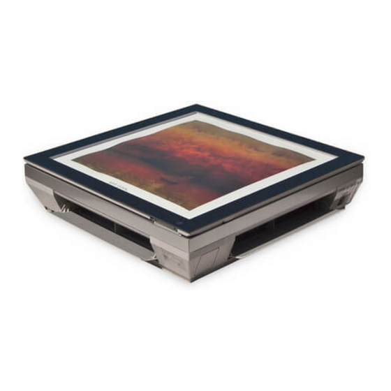
Page 36: How To Replace Picture & Photograph
In case a mat is not used, recommended size of a photo/picture: 522mm x 522mm When powering on after replacing filter and picture, the front panel doesn't intervene. 522mm 522mm - 36 - Copyright ©2010 LG Electronics. Inc. All right reserved. LGE Internal Use Only Only for training and service purposes... -
Page 37: Operation
• The louver can be set at the desired position or swing up indoor pipe temperature will be and down automatically. reached at 82°F(28°C). - 37 - Copyright ©2010 LG Electronics. Inc. All right reserved. LGE Internal Use Only Only for training and service purposes... -
Page 38: The Function Of Main Control
• Compressor and outdoor fan stop when indoor pipe temperature is below 32°F(0°C) and restart at the pipe temperature is above 45°F(7°C). - 38 - Copyright ©2010 LG Electronics. Inc. All right reserved. LGE Internal Use Only Only for training and service purposes... - Page 39 INTAKE AIR TEMP. SETTING TEMP. +1°F (Compressor OFF) SETTING TEMP. -1°F (Compressor ON) INDOOR FAN SPEED The electronic control operation COMPRESSOR - 39 - Copyright ©2010 LG Electronics. Inc. All right reserved. LGE Internal Use Only Only for training and service purposes...
- Page 40 ➲ Setting Temp-1°F Compressor OFF Temp. • In 10-min dehumidification operation, the indoor fan operates with the low airflow speed. - 40 - Copyright ©2010 LG Electronics. Inc. All right reserved. LGE Internal Use Only Only for training and service purposes...
- Page 41 • The operation diagram is shown below. INDOOR PIPE 1min TEMP. 82°F 78°F Selecting INDOOR FAN SPEED fan speed COMPRESSOR - 41 - Copyright ©2010 LG Electronics. Inc. All right reserved. LGE Internal Use Only Only for training and service purposes...
- Page 42 3 minutes 3 minutes 3 minutes INDOOR FAN SPEED Low or OFF Low or OFF Low or OFF COMPRESSOR - 42 - Copyright ©2010 LG Electronics. Inc. All right reserved. LGE Internal Use Only Only for training and service purposes...
-
Page 43: Test Operation
- Press and hold the ON/OFF button for 6 seconds, then the buzzer sound 2 "beep" and the indicator lamp (1) brights 4 times. - 43 - Copyright ©2010 LG Electronics. Inc. All right reserved. LGE Internal Use Only Only for training and service purposes... -
Page 44: Display Function
• Outdoor pipe temperature • Outdoor TH assy check thermistor open/short. 3sec 3sec (5times) • Communication line/circuit • Poor communication. check 3sec - 44 - Copyright ©2010 LG Electronics. Inc. All right reserved. LGE Internal Use Only Only for training and service purposes... -
Page 45: Remote Control Operations
Used to set Auto Clean mode. 18. °C/°F SWITCH BUTTON Used to switch temperature reading from Centigrade to Fahrenheit. - 45 - Copyright ©2010 LG Electronics. Inc. All right reserved. LGE Internal Use Only Only for training and service purposes... -
Page 46: Disassembly
- Remove securing screws. Motor Connector - Pull the control box out from the chassis carefully. Sensor Connector - 46 - Copyright ©2010 LG Electronics. Inc. All right reserved. LGE Internal Use Only Only for training and service purposes... - Page 47 - Remove 4 screws securing motor mount from the chassis and lift up the motor mount and the bracket. Motor Mount Bolt - 47 - Copyright ©2010 LG Electronics. Inc. All right reserved. LGE Internal Use Only Only for training and service purposes...
-
Page 48: Schematic Diagram
Schematic Diagram Schematic Diagram Heat Pump/Cooling Only Series(Indoor Unit) - 48 - Copyright ©2010 LG Electronics. Inc. All right reserved. LGE Internal Use Only Only for training and service purposes... -
Page 49: Heat Pump Series (Outdoor Unit)
Schematic Diagram Heat Pump Series/ Cooling Only Series (Outdoor Unit) - 49 - Copyright ©2010 LG Electronics. Inc. All right reserved. LGE Internal Use Only Only for training and service purposes... -
Page 50: Indoor Unit P.w.b. Assembly
Schematic Diagram INDOOR UNIT P.W.B. ASSEMBLY • P/No.: 6871A20999A (PCB ASSEMBLY, MAIN) Top View Bottom View - 50 - Copyright ©2010 LG Electronics. Inc. All right reserved. LGE Internal Use Only Only for training and service purposes... -
Page 51: Outdoor Unit P.w.b. Assembly
Schematic Diagram OUTDOOR UNIT P.W.B. ASSEMBLY • P/No.: 6871A20901C (PCB ASSEMBLY, MAIN) Top View Bottom View - 51 - Copyright ©2010 LG Electronics. Inc. All right reserved. LGE Internal Use Only Only for training and service purposes... -
Page 52: Display P.w.b. Asm
Schematic Diagram DISPLAY P.W.B. ASM • P/No.: 6871A20921A (PCB ASSEMBLY) - 52 - Copyright ©2010 LG Electronics. Inc. All right reserved. LGE Internal Use Only Only for training and service purposes... -
Page 53: Wiring Diagram
Schematic Diagram Wiring Diagram (1) Indoor Unit (Cooling Only Models, & Heating Models) - 53 - Copyright ©2010 LG Electronics. Inc. All right reserved. LGE Internal Use Only Only for training and service purposes... - Page 54 Schematic Diagram (2) Outdoor Unit(Cooling Only Models, & Heating Models) - 54 - Copyright ©2010 LG Electronics. Inc. All right reserved. LGE Internal Use Only Only for training and service purposes...
-
Page 55: Troubleshooting Guide
CHECK VALVE LIQUID SIDE CAPILLARY TUBE HEAT HEAT EXCHANGE EXCHANGE (EVAPORATOR) (CONDENSER) GAS SIDE REVERSING VALVE COOLING COMPRESSOR HEATING - 55 - Copyright ©2010 LG Electronics. Inc. All right reserved. LGE Internal Use Only Only for training and service purposes... -
Page 56: Pipe Length And The Elevation
CAUTION: Capacity is based on standard length and maximum allowance length is on the basis of reliability. Oil trap should be installed every 16.4~23feets (5~7 meters). - 56 - Copyright ©2010 LG Electronics. Inc. All right reserved. LGE Internal Use Only Only for training and service purposes... -
Page 57: 3-Way Valve
– Open the low-pressure valve on the charge set slightly to air purge from the charge hose. (5) Set the liquid side valve to the closed position. - 57 - Copyright ©2010 LG Electronics. Inc. All right reserved. LGE Internal Use Only Only for training and service purposes... -
Page 58: Re-Air Purging
– Close the valve on the gas cylinder and discharge the refrigerant until the gauge indicates 3 to 5 kg/cm - 58 - Copyright ©2010 LG Electronics. Inc. All right reserved. LGE Internal Use Only Only for training and service purposes... - Page 59 – Discharge the refrigerant gradually; if it is discharged too suddenly, the refrigeration oil will also be discharged. - 59 - Copyright ©2010 LG Electronics. Inc. All right reserved. LGE Internal Use Only Only for training and service purposes...
- Page 60 (4) Disconnect the charge hose from the vacuum pump. – Vacuum pump oil. If the vacuum pump oil becomes dirty or depleted, replenish as needed. - 60 - Copyright ©2010 LG Electronics. Inc. All right reserved. LGE Internal Use Only Only for training and service purposes...
-
Page 61: Gas Charging
This unit is charged with R-410A. minute and then repeat the procedure Pay attention not to charge R-22. (pumping down-pin). - 61 - Copyright ©2010 LG Electronics. Inc. All right reserved. LGE Internal Use Only Only for training and service purposes... - Page 62 P = 3 + 0.0123 x T + 0.8 x T . g) Where, P : Suction Pressure(kg/cm Tout : Outdoor Temperature(˚C) : Indoor Temperature(˚C) - 62 - Copyright ©2010 LG Electronics. Inc. All right reserved. LGE Internal Use Only Only for training and service purposes...
-
Page 63: Cycle Parts
2. The temperature can be measured by attaching the thermometer to the low pressure tubing and wrap it with putty. - 63 - Copyright ©2010 LG Electronics. Inc. All right reserved. LGE Internal Use Only Only for training and service purposes... -
Page 64: Electronic Parts
• Voltage of Outdoor unit Micom No. 18, OSC01B(4MHz) Voltage of Indoor unit Micom No. 43 and (Indoor/Outdoor unit) soldering condition • Replace faulty parts - 64 - Copyright ©2010 LG Electronics. Inc. All right reserved. LGE Internal Use Only Only for training and service purposes... -
Page 65: The Product Is Not Operate With The Remote Controller
• Check the connecting circuit between PIN ㊸ - R11L(1K) - C11L(680PF) - MICOM PIN • Check Receiver Ass'y - 65 - Copyright ©2010 LG Electronics. Inc. All right reserved. LGE Internal Use Only Only for training and service purposes... -
Page 66: Compressor/Outdoor Fan Are Unable To Drive
• Check the electrical wiring diagram of outdoor side. • Check the abnormal condition for the component of Compressor/Outdoor Fan Motor. - 66 - Copyright ©2010 LG Electronics. Inc. All right reserved. LGE Internal Use Only Only for training and service purposes... -
Page 67: When Indoor Fan Does Not Operate
※ Indoor Fan is to be stopped when Indoor pipe(coil) termperature is lower than 79°F. (At that times, Defrost indicator is turned on) - 67 - Copyright ©2010 LG Electronics. Inc. All right reserved. LGE Internal Use Only Only for training and service purposes... -
Page 68: When Vertical Louver Does Not Operate
• Confirm the assembly conditions that are catching and interfering parts in the rotation radial of the Vertical Louver - 68 - Copyright ©2010 LG Electronics. Inc. All right reserved. LGE Internal Use Only Only for training and service purposes... -
Page 69: When A Comunication Error Occurs
Outdoor unit is applied, a communication error will occur. Therefore, the power should be applied after connecting them. - 69 - Copyright ©2010 LG Electronics. Inc. All right reserved. LGE Internal Use Only Only for training and service purposes... - Page 70 • The operation indicator blinks once (on for 0.5 second, off for 3 seconds) (① and ②) of PIPE-TH. • Continuous operation - 70 - Copyright ©2010 LG Electronics. Inc. All right reserved. LGE Internal Use Only Only for training and service purposes...
- Page 71 (③ ↔ ④) • The RED indicator of the Outdoor unit blinks 5 times after 2 minutes with applying the power. - 71 - Copyright ©2010 LG Electronics. Inc. All right reserved. LGE Internal Use Only Only for training and service purposes...
- Page 72 DC/DC 15.87 15.87 15.87 15.87 15.87 35.5 32.96 25.17 17.28 OUTDOO R CN- DC/DC 15.87 15.87 15.87 15.87 15.87 - 72 - Copyright ©2010 LG Electronics. Inc. All right reserved. LGE Internal Use Only Only for training and service purposes...
-
Page 73: Exploded View
Please ensure GCSC since the replacement parts may be changed demending upon the buyer's request. Please check the correct parts in View RPL(Replacement Part List)on GCSC. (GCSC Website http://biz.Lgservice.com) - 73 - Copyright ©2010 LG Electronics. Inc. All right reserved. LGE Internal Use Only Only for training and service purposes... - Page 74 Please ensure GCSC since the replacement parts may be changed demending upon the buyer's request. Please check the correct parts in View RPL(Replacement Part List)on GCSC. (GCSC Website http://biz.Lgservice.com) - 74 - Copyright ©2010 LG Electronics. Inc. All right reserved. LGE Internal Use Only Only for training and service purposes...
- Page 75 Please ensure GCSC since the replacement parts may be changed demending upon the buyer's request. Please check the correct parts in View RPL(Replacement Part List)on GCSC. (GCSC Website http://biz.Lgservice.com) - 75 - Copyright ©2010 LG Electronics. Inc. All right reserved. LGE Internal Use Only Only for training and service purposes...
- Page 76 1. Please call the installing contractor of your product, as warranty service will be provided by them. 2. If you have service issues that have not been addressed by the contractor, please call 1-888-865-3026. CANADA Service call Number # : (888) LG Canada, (888) 542-2623 FEBRUARY, 2010 P/NO : 3828A20926C...