
Related Manuals for DèLonghi DSC 95 E

Summary of Contents for DèLonghi DSC 95 E
- Page 1 Users Operating Instructions Before operating this cooker, please read these instructions carefully DSC 95 E Ceramic Cooker...
- Page 2 Introduction Congratulations on your purchase of this Delonghi ceramic cooker which has been carefully designed and produced to give you many years of satisfactory use. Before using this appliance it is essential that the following instructions are carefully read and fully understood. We would emphasise that the installation section must be fully complied with for your safety to ensure that you obtain the maximum benefits from your appliance.
- Page 3 IMPORTANT INSTRUCTIONS AND ADVICE FOR THE USE OF ELECTRICAL APPLIANCES The use of any electrical appliance requires the compliance with some basic rules, namely: – do not touch the appliance with wet or damp hands (or feet) – do not use the appliance whilst in bare feet –...
- Page 4 IMPORTANT SAFEGUARDS AND RECOMMENDATIONS After having unpacked the appliance, check to ensure that it is not damaged. In case of doubt, do not use it and consult your supplier or a professionally qualified technician. Packing elements (i.e. plastic bags, polystyrene foam, nails, packing straps, etc.) should not be left around within easy reach of children, as these may cause serious injuries.
- Page 5 ■ The various components of the appliance are recyclable. Dispose of them in accordance with the regulations in force in your country. If the appliance is to be scrapped, remove the power cord. ■ Always use oven gloves when removing the shelves and food trays from the oven whilst hot.
-
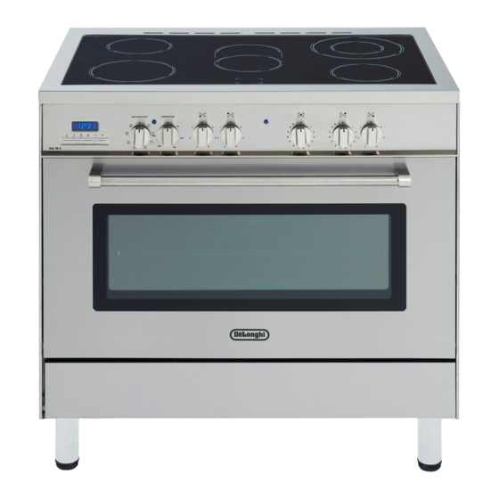
Page 6: Cooking Hob
Cooking hob Fig. 1.1 VITROCERAMIC COOKING HOB 1. 3 circuits cooking zone Ø 180 1700 W 2. 3 circuits cooking zone Ø 145 1200 W 3. Oval double cooking zone Ø 145 x 250 1800/1000 W 4. Double cooking zone Ø... -
Page 7: Control Panel
Control panel Fig. 2.1 CONTROL PANEL - Controls description 1. Electronic programmer 2. Multifunction oven switch knob 3. Multifunction oven thermostat knob 4. Front left cooking zone control knob 5. Rear left cooking zone control knob 6. Central cooking zone control knob 7. -
Page 8: Electronic Programmer
Electronic programmer The electronic programmer is a device that groups together the following functions: – 24 hour clock with illuminated display – Timer (up to 23 hours and 59 minutes) – Programme for automatic oven cooking – Programme for semi-automatic oven cooking. Description of the buttons: Automatic cooking taking place Timer... -
Page 9: Electronic Clock
ELECTRONIC CLOCK ELECTRONIC TIMER (fig. 3.2) The programmer is equipped with an The timer programme consists only of a electronic clock with lighted numbers buzzer which may be set for a which indicate hours and minutes. maximum period of 23 hours and 59 Upon immediate connection of the minutes. -
Page 10: Automatic Oven Cooking
AUTOMATIC OVEN 3.Set the temperature and the cooking programme by using the switch and COOKING thermostat knobs of the oven (see To cook food automatically in the oven, specific chapters). it is necessary to: 1.Set the length of the cooking time Now the oven is programmed and 2.Set the end of the cooking time everything will work automatically, that... -
Page 11: Semi-Automatic Cooking
At the end of cooking, the oven and SEMI-AUTOMATIC symbol will turn off, the AUTO COOKING will flash and a buzzer will sound; that can be stopped by pushing any of the This is used to automatically switch off buttons. the oven after the desired cooking time has elapsed. -
Page 12: How To Use The Vitroceramic Hob
How to use the vitroceramic hob The ceramic surface of the hob allows a IMPORTANT NOTE: fast transmission of heat in the vertical The heating elements incorporate a direction, from the heating elements thermolimiter that switches the element underneath the ceramic glass to the ON/OFF during all the settings to pro- pans sat on it. - Page 13 DOUBLE AND OVAL RADIANT ZONES The heating element is formed of a coil of resistant material which reaches the working temperature quickly. Operation of the cooking zone is con- trolled by a continuous energy regulator from 1 to 12 (maximum temperature) (fig.
-
Page 14: Cooking Hints
COOKING HINTS Cooking zone Cooking zone controlled by a controlled by Knob Type of cooking 7 position a 12 position setting switch energy regulator Switched OFF For melting operations (butter, chocolate). To maintain food hot and to heat small quantities of liquid (sauces, eggs). -
Page 15: Residual Heat Indicators
RESIDUAL HEAT INDICATORS COOKING HINTS: The hob also features 5 warning lights – To reduce the cooking time, you can which are connected to the correspond- turn the control knob to the max when ing plates. you switch the plate on. After a short time you can set the con- When the temperature of a cooking trol knob to the position required for... -
Page 16: Safety Hints
CLEANING THE HOB SAFETY HINTS: Before you begin cleaning make – Before you switch the hob on, make sure that the appliance is switched sure you know which knob controls the off. required cooking plate. We advise you to set the pan over the cooking plate before switching it on. -
Page 17: General Features
Multifunction oven OPERATING PRINCIPLES Attention: oven door becomes very hot during opera- Heating and cooking in the MULTI- FUNCTION oven are obtained in the tion. Keep children away. following ways: a. by normal convection The heat is produced by the upper GENERAL FEATURES and lower heating elements. -
Page 18: Thermostat Knob
Fig. 5.2 Fig. 5.1 THERMOSTAT KNOB (Fig. 5.2) This only sets the cooking temperature and does not switch the oven on. Rotate clock- wise until the required temperature is reached (from 50 to 250 °C). The light above the temperature selector will illuminate when the oven is swiched on and turns off when the oven reaches the correct temperature. -
Page 19: Fan Grill
GRILLING The infrared grill element comes on. The heat is dispersed by radiation. Set the thermostat knob to between 50 °C and 200 °C. Always grill with the oven door closed. For cooking hints, see the chapter “USE OF THE GRILL”. Recommended for: Intense grilling, browning, cooking au gratin and toasting etc. -
Page 20: Multi-Function
MAINTAINING TEMPERATURE AFTER COOKING OR SLOWLY HEATING FOODS The upper element, the circular element and the fan come on. The heat is circulated by forced convection with greater intensity in the upper part. The temperature can be set to between 50 °C and 140 °C via the thermostat knob. Recommended for: Keeping food warm after any type of cooking. -
Page 21: Use Of The Grill
WARMING BREAD Set the switch to position and the thermostat knob to position 150 °C. Bread becomes fragrant again if wet with a few drops of water and put into the oven for about 10 minutes at the highest temperature. SIMULTANEOUS COOKING OF DIFFERENT FOODS The oven set on position can cook several different foods together. -
Page 22: Cooking Guide
Cooking guide Temperature and times given are approximate, as they will vary depending on the quality and amount of food being cooked. Remember to use ovenproof dishes and to adjust the oven temperature during cooking if necessary. APPROX. HEAT OF TYPE OF DISH TO COOK TEMPERATURE OVEN... -
Page 23: Important Notes
Important notes Installation, and any demonstration, information or adjustments are not included in the warranty. The cooker must be installed by a qualified person in accordance with the relevant Standards. Attention The appliance gets very hot, mainly around the cooking areas. It is very important that children are not left alone in the kitchen when you are cooking. -
Page 24: For Your Safety
Do’ s and do not’ s • Do always grill with the oven door closed. • Do read the user instructions carefully before using the cooker for first time. • Do allow the oven to heat for one and a half hours, before using for the first time, in order to expel any smell from the new oven insulation, without the introduction of food. -
Page 25: Cleaning And Maintenance
Cleaning and maintenance GENERAL ADVICE As a safety measure, before you start cleaning the cooker be sure to disconnect it from the mains supply. Do not use a steam cleaner because the moisture can get into the appliance thus make it unsafe. The use of suitable protective clothing/gloves is recommended when han- dling or cleaning of this appliance. -
Page 26: Storage Compartment
OVEN DOOR STORAGE COMPARTMENT The internal glass panel can be easily The storage compartment is accessible removed for cleaning by unscrewing through the pivoting panel (fig. 7.2). the 4 retaining screws (Fig. 7.1). Do not use harsh abrasive cleaners Do not store flammable material or sharp metal scrapers to clean in the oven or in the storage the oven door glass since they can... -
Page 27: Replacing The Oven Light Bulb
INSIDE OF OVEN The oven should always be cleaned after use when it has cooled down. The cavity should be cleaned using a mild detergent solution and warm water. Suitable proprietary chemical cleaners may be used after first consulting with the manufacturers recommendations and testing a small sample of the oven cavity. -
Page 28: Oven Floor
OVEN TRAY The oven tray must be correctly placed on the wire support (fig. 7.5) then inserted into the side runners (fig. 7.6). OVEN FLOOR The oven floor “F” (fig. 7.6) can be easily removed to facilitate cleaning. Remember to replace the floor correctly afterwards. Be careful not to confuse the tray “L”... -
Page 29: Removing The Oven Doors
REMOVING THE OVEN Fig. 7.7A DOORS The oven doors can easily be removed as follows: – Open the door to the full extent (fig. 7.7A). – Attach the retaining rings to the hooks on the left and right hinges (fig. 7.7B). -
Page 30: Advice For The Installer
Advice for the installer IMPORTANT – Cooker installation must only be carried out by QUALIFIED TECHNICIANS and in compliance with local safety standards. Failure to observe this rule will invalidate the warranty. – Some appliances are supplied with a protective film on steel and aluminium parts. This film must be removed before using the cooker. -
Page 31: Installation
Installation Important – The appliance should be installed by a qualified electrician in compliance with the laws in force in your country and in observation of the instructions supplied by the manufacturer. Failure to comply with this condition will render the guarantee invalid. –... -
Page 32: Fitting The Adjustable Feet
FITTING THE ADJUSTABLE FEET The adjustable feet must be fitted to the base of the cooker before use. Rest the rear of the cooker on a piece of the polystyrene packaging exposing the base for the fitting of the feet. Fig. -
Page 33: Moving The Cooker
MOVING THE COOKER WARNING When raising cooker to upright position always ensure two people carry out this manoeuvre to pre- vent damage to the adjustable feet (fig. 8.5). WARNING Be careful: do not lift the cooker by the door handle when raising to the upright position (fig. -
Page 34: Stability Bracket
Stability bracket We recommend a stability bracket is fitted to the cooker. The type shown in fig. 8.8 can be purchased from most plumbers merchants and do it yourself (D.I.Y.) shops. Existing slot in rear of cooker Bracket Fig. 8.8 Dotted line showing the position of cooker when fixed Outline of cooker... -
Page 35: Electrical Section
Electrical section IMPORTANT: The cooker must be installed in accordance with the manufacturer’ s instructions. Incorrect installation, for which the manufacturer accepts no responsibility, may cause injury to persons, animals or equipment. FOR YOUR SAFETY PLEASE READ THE FOLLOWING INFORMATION: –... -
Page 36: Connecting The Mains Cable
Connecting the power cord must be entrusted to skilled personnel in accordance with the instructions supplied by the manufacturer and in compliance with established safety standards. CONNECTING THE MAINS CABLE To connect the feeder cable to the cooker it is necessary to: –... - Page 39 Descriptions and illustrations in this booklet are given as simply indicative. The manufacturer reserves the right, considering the characteristics of the models described here, at any time and without notice, to make eventual necessary modifications for their construction or for commercial needs.
- Page 40 cod. 1103178 ß4...