
Related Manuals for Honda HPD L15A7


Summary of Contents for Honda HPD L15A7
- Page 1 D L15 gine Insta allati on M Manu B-1 a and D DB-6 6 Cha assis /2010 ...
-
Page 2: Table Of Contents
Swift Chassis DB-1 & DB-6 L15A7 Engine Installation Manual Table of Contents 1. Safety Consideration and Warnings ............. Page 2 2. Title Page ..................... Page 3 3. Bell Housing Adapter Preparation ............Page 4 4. Install Slave Cylinder ................Page 6 5. -
Page 3: Safety Consideration And Warnings
Any person who intends to use a replacement part, a service procedure, or a tool that is not recommended by Honda or the race sanctioning body, must determine the risk to their personal safety, and the safe operation of the vehicle. -
Page 4: Title Page
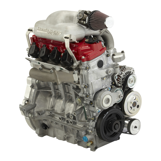
Swift Chassis DB-1 & DB-6 L15A7 Engine Installation Manual This manual details the steps necessary to install the Honda L15A7 engine with the HPD engine kit into a Swift DB-1 / DB-6 chassis. The converted L15A7 engine is designed to be installed utilizing the existing mounting points of your chassis without modification. -
Page 5: Bell Housing Adapter Preparation
Swift Chassis DB-1 & DB-6 L15A7 Engine Installation Manual Bell Housing Adapter Preparation Adaptor plate. Internal hex bolt 3/8-24 x 1-3/4” (2x) Internal hex bolt 3/8-24 x 1-1/2” (2x) Dowel - 12 x 10mm (2x) Dowel – 14 x 20mm (2x) Spherical Bearing (DB-1) Circlip, Internal –... - Page 6 Swift Chassis DB-1 & DB-6 L15A7 Engine Installation Manual Bell Housing Adapter Preparation cont’d Install the locating dowels. Dowels Mock up the adapter plate to the engine. Note the area where the shifter rod passes through. This area will need to be tapered towards the bearing.
-
Page 7: Install Slave Cylinder
Swift Chassis DB-1 & DB-6 L15A7 Engine Installation Manual Install Slave Cylinder For the DB-1 Install the HPD supplied slave cylinder using the same procedure used for the Swift slave cylinder. NOTE: Use new seals and backing rings. Install a new release bearing onto the slave cylinder. - Page 8 Swift Chassis DB-1 & DB-6 L15A7 Engine Installation Manual Install Slave Cylinder cont’d For the DB-6 Remove the release bearing from the Swift assembly. Press on the HPD supplied adapter. Install the new release bearing. Clutch Slave Cylinder Placement 1. Measure distance from the back of the engine block to the end of the clutch fingers. This is dimension “A”...
-
Page 9: Modify Shifter Rod
Swift Chassis DB-1 & DB-6 L15A7 Engine Installation Manual Modify Shifter Rod DB-1 Only The middle shifter rod will need to be modified to clear the C.V. joint flange. HPD has supplied the rod for the rear shifter link. C.V. Joint Flange Clearanced Area The middle Apex joint will need to be moved forward by 4 inches. -
Page 10: Bell Housing / Oil Tank Preparation
Swift Chassis DB-1 & DB-6 L15A7 Engine Installation Manual Bell Housing / Oil Tank Preparation – DB-1 & DB-6 Using Hondalock 2, or its equivalent, install the AN -10 plug in the upper left oil return port. This is now an engine mounting point. -
Page 11: Install Fuel System
Swift Chassis DB-1 & DB-6 L15A7 Engine Installation Manual Install Fuel System – DB-1 & DB-6 The Fit Fuel system consists of the fuel pump, fuel filter, regulator, assorted fittings and hoses. If you are using your own hose supply, ensure that it is rated for high pressure fuel injection systems. The HPD-kitted fuel system runs at 50-60 PSI. - Page 12 Swift Chassis DB-1 & DB-6 L15A7 Engine Installation Manual Install Fuel System – DB-1 & DB-6 cont’d Regulator Housing Install the regulator into the housing using a light oil or silicone lubricant on the O-rings. Make sure to insert the regulator square, as it will be easy to cut the O-rings.
- Page 13 Swift Chassis DB-1 & DB-6 L15A7 Engine Installation Manual Install Fuel System – DB-1 & DB-6 cont’d Using the pipe thread sealant, install the 5/16‟ Barb to AN-4 ORB adaptor into the housing, on the fuel cell (bottom) side. This will connect to the fuel pump.
- Page 14 Swift Chassis DB-1 & DB-6 L15A7 Engine Installation Manual Install Fuel System – DB-1 & DB-6 cont’d Find the depth of your fuel cell. Depending on your fuel cell configuration, you may need to remove the two middle sections of fuel cell foam.
- Page 15 Swift Chassis DB-1 & DB-6 L15A7 Engine Installation Manual Install Fuel System – DB-1 & DB-6 cont’d Clock the fuel pump pick up towards the rear of the cell. Clock the regulator housing so fuel is returned over the pickup. Tighten all of the connections.
- Page 16 Swift Chassis DB-1 & DB-6 L15A7 Engine Installation Manual Install Fuel System – DB-1 & DB-6 cont’d Fuel hose routing There are 4 cushion clamps supplied with the kit to mount the fuel filter. Using the adaptors and reducers connect the fuel test port to the „out‟ side of the fuel filter.
- Page 17 Swift Chassis DB-1 & DB-6 L15A7 Engine Installation Manual Install Fuel System – DB-1 & DB-6 cont’d ° Install the third 45 push-loc onto the supplied hose. Connect this to the „vent‟ fitting on the fuel cell cover, route it the same as the fuel feed line.
-
Page 18: Engine Installation
Swift Chassis DB-1 & DB-6 L15A7 Engine Installation Manual Engine Installation Install the lower rear mounting studs. This engine will install in the same manner as your previous engine. Be sure the water lines are installed on the engine per the engine race kit manual. - Page 19 Swift Chassis DB-1 & DB-6 L15A7 Engine Installation Manual Engine Installation cont’d Loosely install the upper front mount. Be sure the top hat is in the flange on the head from the bottom. (From Engine Kit Installation Manual – Pg 17). Slide the engine into position;...
- Page 20 Swift Chassis DB-1 & DB-6 L15A7 Engine Installation Manual Engine Installation cont’d Align the input shaft splines with the clutch and mate the bell housing to the engine. When you have the dowels engaged, you can thread in the four bolts and snug up the bell housing.
-
Page 21: Oil System
Swift Chassis DB-1 & DB-6 L15A7 Engine Installation Manual Oil System Layout all the hose and fittings before assembly to understand how the hoses are to be placed. NOTE: If you are cutting the braided hose to length and installing the fittings yourself be sure you are familiar with the proper procedures. - Page 22 Swift Chassis DB-1 & DB-6 L15A7 Engine Installation Manual Oil System cont’d Route the breather lines, being sure to check the following items: 1. That the 2mm breather restrictor is in the valve cover. 2. That the valve cover breather is not interfering with the operation of the rear anti roll bar.
-
Page 23: Install Modified Shifter Rod
Swift Chassis DB-1 & DB-6 L15A7 Engine Installation Manual Install Modified Shifter Rod Install the HPD supplied rear shifter rod. Install the bolt to the shaft and selector fork at the gearbox. Line up the shifter lever in the cockpit and mark through the middle Apex joint to place the new bolt hole. - Page 24 Swift Chassis DB-1 & DB-6 L15A7 Engine Installation Manual Install Modified Shifter Rod cont’d Install the middle shifter rod; tighten all bolts securing the shifter rod and check that you can select all the gears. Make fine adjustments at the lever- end in the cockpit if necessary.
-
Page 25: Miscellaneous
Install the exhaust system. Depending on your previous system you will need to adjust the height of the tail pipe support. Install the Lambda sensor per the Honda Fit service manual. Plug into the engine harness. 8/2010... -
Page 26: Completed Install
Swift Chassis DB-1 & DB-6 L15A7 Engine Installation Manual Completed Install Left Side View Right Side View 8/2010... - Page 27 See „Operating Parameters‟ section of your L15A7 Engine Kit Assembly Manual. NOTE: HPD recommends installing a 19-20psi radiator cap. Follow the Honda Fit Service manual guidelines for all fluid recommendations. Connect the brake and clutch lines. Bleed the systems as normal.
-
Page 28: Engine Side Cover Blister Installation
Swift Chassis DB-1 & DB-6 L15A7 Engine Installation Manual Engine Side Cover Blister Installation By Stan Clayton Dauntless Racing Cars, February 2010 Safety Precautions Personnel undertaking this procedure should read and understand all relevant MSDS documents before using resins, hardeners, catalysts and solvents, as they can be hazardous to one's health. Use appropriate safety equipment at all times while working with these materials, with a minimum of long sleeves, protective gloves, respirator and eye protection. - Page 29 2. Before attempting to match the blister to each side cover, fit the side cover to the chassis with the Honda Fit engine fully installed and mark the inside of the side cover where the obstruction strikes it. Remove the side cover from the chassis and carefully cut away a minimum of material to clear the obstruction.
- Page 30 Swift Chassis DB-1 & DB-6 L15A7 Engine Installation Manual Engine Side Cover Blister Installation cont’d 7. It is now time to fit the blister to the side cover and tape the outside with 2" masking tape. Ensure the entire outside outline of the opening is covered with masking tape, or resin may leak out onto the outer surface of the side cover.
-
Page 31: Contact Information
Swift Chassis DB-1 & DB-6 L15A7 Engine Installation Manual Contact Information Honda Performance Development, Inc. 25145 Anza Drive Santa Clarita, CA. 91355 661-294-7300 Honda Racing Line grmsadmin@hra.com Phone: 661-702-7777 Fax: 661-294-7367 8/2010...