Motorola CDM-Series Service & Installation Manual
Cdm-series control station
Hide thumbs
Also See for CDM-Series:
- Detailed service manual (686 pages) ,
- Service manual (180 pages) ,
- Basic service manual (92 pages)

Related Manuals for Motorola CDM-Series


Summary of Contents for Motorola CDM-Series
-
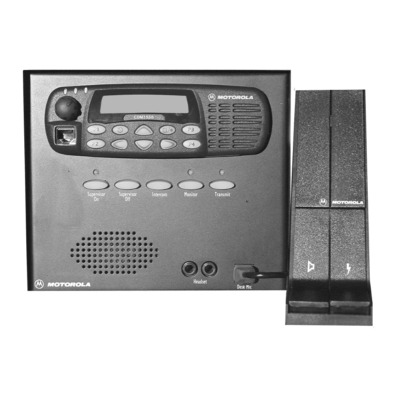
Page 1: Control Station
Professional Series Two-Way Radio Service & Installation Manual CDM-Series Control Station... -
Page 2: Computer Software Copyrights
You agree not to reverse engineer or create derivative works of the SOFTWARE; not to transmit the SOFTWARE electroni- cally; not to modify, configure, or use the SOFTWARE in any manner not authorized by MOTOROLA; and, except as an inte- gral part of the product, not to rent, lease, or convey the SOFTWARE. -
Page 3: Table Of Contents
Table of Contents Foreword Scope of Manual ................iii How to Use This Manual. - Page 4 Table of Contents CDM Control Station Receiving Calls................2 Initiating Calls .
-
Page 5: Foreword
Include the RMA number in the package with the defective unit. For a list of Motorola-approved antennas, batteries, and other accessories, visit the following web site which lists approved For information on warranty service, returns or repairs, accessories: http://www.motorola.com/cgiss/index.shtml. -
Page 6: Accessories
Foreword CDM Control Station Accessories Accessories Motorola offers several accessories to increase communications efficiency. Many of the accessories available are listed below, but for a complete list, consult your Motorola dealer. Desksets L3211 MC1000 Basic Local Deskset L3212 MC1000 DC Remote Control Deskset with 4 Freq. -
Page 7: Service Aids
CDM Control Station Foreword Service Aids Service Aids The following table lists service aids recommended for working on the CDM Control Station. Motorola Part No. Description Application HLN9214 Radio Interface Box Enables communication between the radio and the computer’s serial communications adapter. - Page 8 Foreword CDM Control Station Test Equipment 6880309N15-A October, 2004...
-
Page 9: Introduction To The Cdm Control Station
Section 1 Introduction to the CDM Control Station Overview Physical Description This section introduces you to the CDM Control Station; out- The following paragraphs describe the physical characteris- lines major components; physical appearance; accessories; tics of the Control Station. general information about cables, and basic assembly of the Control Station. -
Page 10: Cdm Control Station Interface Circuit Boards
(approximately 30%) or less power loss. Table 1-2 is a list of Station Audio Panel (CSAP) is located on the housing base Motorola part numbers for the various connectors and just behind the front panel. It provides the physical external cables. -
Page 11: Preventive Maintenance
Table 1-2. Part Numbers for firm. A detailed inspection of the interior electronic circuitry Connectors/Cables (Cont.) is not needed or desired. Part Motorola Part Number Periodic Cleaning type-N male connector 2884476G01 Periodically clean smudges and grime from the exterior type-N 1/2” hardline male TDN6677 housing. - Page 12 Introduction to the CDM Control Station CDM Control Station Preventive Maintenance 6880309N15-A October, 2004...
-
Page 13: Section
Section 2 CDM Control Station Operation Overview Hum and Noise Greater than 45 dB below rated out- puts This section contains information about the control func- tions, audio sources, audio states, programmable features Audio Frequency +/- 3 dB from 300 Hz to 3000 Hz at 1 and operator instructions for the CDM Control Station. -
Page 14: Intercom
CDM Control Station Operation CDM Control Station Audio Sources and Level Adjustments Headset volume of radio RX audio is adjustable via a pot NOTE located on the back panel of the inner chassis. The Control Station is configured at the fac- tory to operate with a desk microphone. - Page 15 CDM Control Station CDM Control Station Operation Operator Instructions button while speaking into the microphone. Release the but- • Internal Microphone ton to listen. Transmission is accomplished by using one of The Control Station comes equipped with an internal the following microphones: microphone intended for use in low noise environ- ments.
- Page 16 CDM Control Station Operation CDM Control Station Operator Instructions 6880309N15-A October, 2004...
-
Page 17: Overview
Section 3 CDM Control Station Installation Overview Switch 4, Mute Accessory RX Audio During Intercom This section contains information about the setup and instal- When switch 4 is on, radio RX audio to the accessory RX lation of the CDM Control Station. Audio line will be muted during Intercom (pushing the front panel "Intercom"... -
Page 18: Additional Considerations
Observe proper procedures for handling ESD sen- trol Station. Immediately report any missing or damaged sitive devices. items to Motorola Product Services. Remove the six (6) TT3.5mm, pan head Taptite The following steps explain how to disassemble the Control screws, located on the sides of the housing using a Station housing and how to reassemble it while installing the Torx T15 driver. -
Page 19: Assembling The Cdm Control Station Housing
CDM Control Station CDM Control Station Installation Basic Disassembly/Assembly sis. However, if jumper settings must be changed, Replace the lockwasher and nut onto the connec- disassembly of the inner chassis will be required. tor. Tighten to 2.26 N-m (20 in.-lbs.) torque. Connect the mini-UHF connector of the cable to Remove the screw which secures the CSIM board the antenna connector of the radio. -
Page 20: Attaching The Ac Power Cord
CDM Control Station Installation CDM Control Station Basic Disassembly/Assembly Attaching the AC Power Cord IMPORTANT Before connecting the AC line cord into an Locate the AC power cord and a nylon tie wrap. AC mains outlet, ensure that the "115/230" VAC switch on the power supply is in the Plug the female connector of the AC power cord appropriate position. - Page 21 SCREW, 4-40 x 0.25 LG, Pan, Phillips, Zinc see note NUT, Hex 4-40, Plain, Zinc Note: Non-referenced items cannot be ordered through Motorola, but can be pur- chased at any local hardware store. Figure 3-3. CDM Control Station October, 2004...
- Page 22 SCREW, 4-40 x 0.25 LG, Pan, Phillips, Zinc see note NUT, Hex 4-40, Plain, Zinc HEAD IC / Note: Non-referenced items cannot be ordered through Motorola, but can be pur- chased at any local hardware store. Grounding Stud (w/nut) Antenna “D” Hole...
-
Page 23: Audio Paths
Section 4 CDM Control Station Theory of Operation Audio Paths Digital functions Transmit Audio Mic Selection The mic source for base station transmit and intercom audio is selected by programming switches and the headset sense The headset mic is enabled whenever headset PTT is active. circuit consisting of Q1, Q2, and associated components. - Page 24 CDM Control Station Theory of Operation CDM Control Station Digital functions 6880309N15-A October, 2004...
-
Page 25: Troubleshooting
RX Audio on the radio is set for Fil- page 3-2. tered Audio. Unable to communicate with field ra- Ensure radios are programmed with CDM-Series Programming Software. dios. the correct TPL/DPL code. Verify correct I/O programming of the accessory connector of the control sta- tion radio. - Page 26 CDM Control Station Troubleshooting CDM Control Station 6880309N15-A October, 2004...
-
Page 27: Cdm Control Station Interface Module (Csim), Audio Section
600 mVRMS Reference Filtered Audio 4403 CONRXAUD CNSTNT RXAUD +10V G8_ONHI G1_ONHI 15KP HS_SNS SHEET 2 CTRL 3403 CTRL 10KP U4:B U2:C 4066 6.8K U4:D 4066 220, 25V 4401 POT2 6 IN- G2_ONHI ACC_RX ACC RX LEVEL 2 IN+ 220, 25V DGND U1:B CTRL... -
Page 28: Cdm Control Station Interface Module (Csim), Digital Section
+10V EXTERNAL INPUTS FROM SHEET 3 AUDIO GATING FUNCTIONS TO SHEET 1 U9:D HSRNG1 HSPTT HSPTT U10:A 100KP 1N4148W G1_ONHI DSKPTT U9:E HSRNG2 1N4148W 1N4148W HSPTT SPMUTE SHEET 1 DGND LCLIC +10V LCLPTT U12:B 10KP 1N4148W 1N4148W +10V U10:B U10:C 1N4148W 1N4148W 1N4148W... -
Page 29: Cdm Control Station I/O, Csap And Cskp
FP_LMIC1 LMIC1 P2:1 CBL2:1 Electret FP_LMIC2 P2:2 CBL2:2 LMIC2 FP_BTNGND DGND P2:3 CBL2:3 FP_SONBTN SONBTN P2:4 CBL2:4 FP_SOFFBTN P2:5 CBL2:5 SOFFBTN FP_ICBTN ICBTN P2:6 CBL2:6 FP_MONBTN MONBTN P2:7 CBL2:7 FP_PTTBTN P2:8 CBL2:8 PTTBTN LED1 R113 FP_SUPLED P2:9 CBL2:9 SUPLED LED2 R116 FP_MONLED MONLED... -
Page 30: Cdm Control Station Circuit Board Details
CDM Control Station Audio Panel (CSAP) CDM Control Station Key Panel (CSKP) CDM Control Station Interface Module (CSIM) CDM Control Station Circuit Board Details 6880309N15-A October, 2004... - Page 32 Motorola, Inc. 8000 West Sunrise Boulevard Ft. Lauderdale, FL 33322 MOTOROLA, and the Stylized M Logo, are registered in the U.S. Patent and Trademark Office. All other product or service names are the property of their respective owners. © Motorola, Inc. 2004.