Table of Contents
Advertisement
Printed Matter N°
2954 2100 01
04/2005
Instruction Manual
for AC Generators
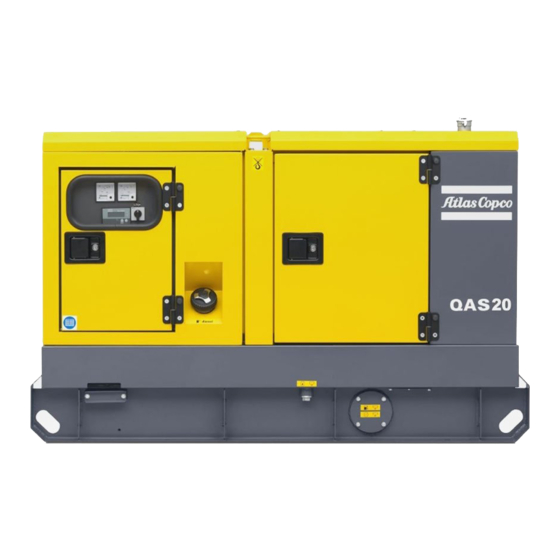
QAS 14 - 20 Pd
Instruction manual .................................................................................. 3
Circuit diagrams .................................................................................... 49
ATLAS COPCO - PORTABLE AIR DIVISION
www.atlascopco.com
Advertisement
Table of Contents
Troubleshooting

Related Manuals for Atlas Copco QAS 14


Summary of Contents for Atlas Copco QAS 14
- Page 1 Instruction Manual for AC Generators QAS 14 - 20 Pd Instruction manual .................. 3 Circuit diagrams ..................49 Printed Matter N° 2954 2100 01 ATLAS COPCO - PORTABLE AIR DIVISION 04/2005 www.atlascopco.com...
- Page 2 The manufacturer does not accept any liability for any damage arising for modifications, additions or conversions made without the manufacturer's approval in writing. Copyright 2005, Atlas Copco Airpower n.v., Antwerp, Belgium. Any unauthorized use or copying of the contents or any part thereof is prohibited.
-
Page 3: Table Of Contents
While every effort has been made to ensure that the information in this manual is correct, Atlas Copco does not assume responsibility for possible errors. Atlas Copco reserves the right to make changes without prior notice. -
Page 4: Safety Precautions For Portable Generators
If any statement in this manual does not comply with local legislation, the stricter of the two shall be applied. The policy of Atlas Copco is to provide the users of their equipment with safe, Statements in these safety precautions should not be interpreted as suggestions, reliable and efficient products. - Page 5 Never refill fuel while the unit is running, unless otherwise stated in the raised position, Atlas Copco Instruction Book (AIB). Keep fuel away from hot parts such - ascertain that the towing eye can swivel freely on the hook, as air outlet pipes or the engine exhaust. Do not smoke when fuelling.
- Page 6 17 Remember that where there is visible dust, the finer, invisible particles will Parts shall only be replaced by genuine Atlas Copco replacement parts. almost certainly be present too; but the fact that no dust can be seen is not a reliable indication that dangerous, invisible dust is not present in the air.
- Page 7 Instruction manual 22 Before clearing the generator for use after maintenance or overhaul, submit it to a testrun, check that the AC power performance is correct and that the control and shutdown devices function correctly. 1.6 Tool applications safety Apply the proper tool for each job. With the knowledge of correct tool use and knowing the limitations of tools, along with some common sense, many accidents can be prevented.
-
Page 8: Leading Particulars
Leading particulars 2.1 General description The QAS 14 and QAS 20 are AC generators, built for continuous The QAS 14 and QAS 20 generators are driven by a fluid-cooled running at sites where no electricity is available or as stand-by in diesel engine, manufactured by PERKINS. -
Page 9: Bodywork
The earthing rod, connected to the generator’s earth terminal is Indicates the 3-way valve. located at the side of the frame. 2.3 Markings QAS 14 Pd, QAS20 Pd Indicates the partnumbers of the different Yearly (max. 500h) 2912 6041 04... -
Page 10: Control And Indicator Panel Qc1001
QAS 14 - 20 Pd 2.5 Control and indicator panel Qc1001™ 2.5.1 General description Qc1001™ control 2.5.3 Pushbutton and LED functions panel Following pushbuttons are used on the Qc1001™: ENTER: Is used to select and confirm changed settings in the Configuration. - Page 11 Instruction manual Following LEDs are used on the Qc1001™: It's possible to scroll through the views, using the UP and DOWN buttons. The scrolling is continuous. ALARM POWER If a Special status comes up, the Status Display is shown. If a Warning comes up, the Warning Display is shown. If a Shutdown comes up, the Shutdown Display is shown.
- Page 12 QAS 14 - 20 Pd View 5 (Service Timers and Battery Voltage) These special statuses are: 150 h 300 h PREHEAT 24.0u The service timer indications count upwards and give an alarm START OFF when the configured value is reached.
- Page 13 Instruction manual > Warning Display (pop-up window) GENERATOR < OVERFREQUENCY 00000.8h GENERATOR UNDERFREQUENCY In case when a Warning occurs, a pop-up window will automatically be entered for as long as the warning is active, no matter which view is active. The warning icons will be shown (together with a continuous lit alarm LED at the fascia), which is SERVICE TIMER 1 centered at the display.
- Page 14 QAS 14 - 20 Pd Shutdown Display (pop-up window) SERVICE TIMER 1 00000.8h SERVICE TIMER 2 In case when a Shutdown occurs, a pop-up window will automatically be entered, no matter which view is active. This pop-up window will stay present until the unit is put in OFF.
- Page 15 The Configuration Menu's are pre-programmed! – Unit Type The Configuration Mode is entered by detection of activation of Unit type 1 for QAS 14 - 20! pushbuttons UP and DOWN at the same time for 3s. – Generator Underfrequency: failclass, enable, delay, setpoint A password will be asked for when an attempt to change a setting is about to be done (user password = “2003”).
-
Page 16: Event Log
QAS 14 - 20 Pd 2.5.5 Fail classes All the activated alarms of the Qc1001™ have their own pre- defined fail class. All alarms are enabled according to one of these three statuses: – disabled alarm, no supervision of alarm (OFF) –... -
Page 17: Control Panel Qc3001
Instruction manual 2.6 Control panel Qc3001™ 2.6.3 Pushbutton functions There are 16 pushbuttons on the display unit. 2.6.1 General description Qc3001™ control panel ALARM: Shows the active alarm list (up to 30 alarms can be listed). JUMP: Each programmable parameter has a channel number in the menu. - Page 18 QAS 14 - 20 Pd 2.6.5 Qc3001™ Menu Overview AUTO: Allows the user to set the generator in AUTO Main View mode. The display has 4 different lines. The information on these lines can change, depending on which view is used. There are 4 different SEMI-AUTO: Allows the user to set the generator in main views possible: SETUP / S3 / S2 / S1.
-
Page 19: Setup Menu
Instruction manual SETUP menu – The fourth line shows the different possible set points. In this example: The control and protection parameters can be programmed "LIM" LIMIT, setting of switch point according the application. This can be done by scrolling through "DEL"... - Page 20 QAS 14 - 20 Pd This is the described menu flow: The menu flow is similar in the CONTROL SETUP, POWER SETUP and SYSTEM SETUP. For more details on the Setup menu we refer to the Qc3001™ User Manual. The JUMP button...
- Page 21 Instruction manual Protection setup: overview of parameters 1090 Reverse Power SERVICE LEVEL 1250 Gen High Frequency 1 CUSTOMER LEVEL 1091 Setpoint -40.0% (-50.0 ... 0.0) 1251 Setpoint 110.0% (100.0 ... 120.0) 1092 Delay (0.1 ... 100.0) 1252 Delay 5.0s (0.2 ... 100.0) 1093 Output Relay A (R0 ...
- Page 22 QAS 14 - 20 Pd 1380 VDO 2.2 SERVICE LEVEL 1480 Oil Pressure SERVICE LEVEL 1381 Setpoint (40 ... 150) 1481 Setpoint (0.0 ... 15.0) 1382 Delay 5.0s 1482 Delay 5.0s (0.0 ... 100.0) (0.0 ... 600.0) 1383 Output Relay A (R0 ...
- Page 23 Instruction manual System setup: overview of parameters 4010 Nominal Settings CUSTOMER LEVEL 4360 Starter CUSTOMER LEVEL 4011 Frequency 50Hz (48.0 ... 62.0) 4361 Start Prepare 1.0s (0.0 ... 600.0) 4012 Generator Power 13kW (10 ... 20000) 4362 Start ON Time 12.0s (1.0 ...
- Page 24 QAS 14 - 20 Pd 4730 Start/Stop Cmd. 3 CUSTOMER LEVEL 4790 GSM Pin Code CUSTOMER LEVEL 4731 Enable (ON / OFF) 4791 Pin code 0000 (0 ... 9999) 4732 START/STOP STOP (START / STOP) 4733 Day(s) (0 / 1 / 2 / 3 / 4 / 5 / 6 / 7 / 8 / 9 / 10)
-
Page 25: Passwords/Fail Classes
Instruction manual 2.6.6 Passwords 2.6.9 Standard modes Changing different parameters requires different password levels. The following modes can be selected (push the dedicated button on Some parameters cannot be changed by the end-customer because the display unit). of safety reasons. Test mode There are 4 different password levels: Enables the user to test the generator on a regular basis. - Page 26 QAS 14 - 20 Pd 2.6.10 Standard applications Automatic Mains Failure (AMF) operation In the Qc3001™ module 3 application types can be selected (in This application is only possible in combination with the Auto channel ). A combination of each application type with the mode.
-
Page 27: Outlet Sockets (S)
Instruction manual 2.7 Outlet sockets (S) 2.8 Spillage free A brief description of all outlet sockets and circuit breakers A Spillage free skid with forklift slots allows the customer to provided on the generator is given hereafter: transport the generator easily with a forklift. X1.2...3-phase outlet socket (400 V AC) It avoids accidential spilling of engine fluids. -
Page 28: Operating Instructions
Consult Atlas Copco for measures against the adverse influence of The generator is wired for a TN-system to IEC 364- non-linear loads. 3, i.e. one point in the power source directly earthed - in this case the neutral. -
Page 29: Before Starting
Instruction manual 3.3 Before starting The voltage drop across a cable can be determined as follows: ⋅ ⋅ ⋅ ⋅ ϕ ⋅ ϕ – With the generator standing level, check the engine oil level and top 3 I L ----------------------------------------------------------------------------- - up if necessary. -
Page 30: Operating Qc3001
QAS 14 - 20 Pd 3.5 Operating Qc3001™ 3.4.2 During operation Qc1001™ Following points should be carried out regularly: 3.5.1 Starting Qc3001™ – Check the engine gauges and the lamps for normal readings. – Turn the optional battery switch to ON. -
Page 31: Maintenance
2912 6043 06 For the most important subassemblies, Atlas Copco has developed service kits that combine all wear parts. These service kits offer you the bene- fits of genuine parts, save on administration costs and are offered at reduced price, compared to the loose components. Refer to the parts list for more information on the contents of the service kits. -
Page 32: Storage Of The Generator
QAS 14 - 20 Pd Storage of the generator Checks and trouble shooting Never perform a test run with connected power 5.1 Storage cables. Never touch an electrical connector without a voltage check. – Store the generator in a dry, frost-free room which is well ventilated. -
Page 33: Alternator Trouble Shooting
Instruction manual 6.4 Alternator trouble shooting Symptom Possible cause Corrective action Alternator does not excite Blown fuse. Replace fuse. Insufficient residual voltage. Increase the speed by 15 %. No residual voltage. For an instant apply on the + and – terminals of the electronic regulator a 12 V battery voltage with a 30 Ω... - Page 34 QAS 14 - 20 Pd 6.5.4 Misfire – Fault in fuel lift pump. – Dirty fuel filter element. – Restriction in a fuel pipe. – Restriction in air filter/cleaner or induction system. – Fault in fuel lift pump. – Air in fuel system.
-
Page 35: Options Available For Qas 14 And Qas 20 Units
7.2 Overview of the electrical options output voltage can be set in the range 23.5-27.5 V respectively 11.8-13.8 V. The following “electrical” options are available for the QAS 14 and QAS 20 units: The LED on the front indicates that the unit is operational. -
Page 36: Output Terminal Board
Interrupts the power supply to X1.1 when a short-circuit occurs at the load side, or when the earth leak detector (30 mA) or the overcurrent protection (QAS 14: 20 A, QAS 20: 32 A) is activated or when the shunt trip is energized. It must be reset manually after eliminating the problem. - Page 37 R). It can be overridden by means of the earth protection (QAS 14: 50 Hz/60 Hz, 20 A, QAS 20: 50 Hz/60 Hz, leak switch (S13, labelled I∆N) but has to be tested monthly 32 A) is activated.
-
Page 38: It-Relay
Interrupts the power supply X.1.1 when a short-circuit occurs This refinery equipment option consists of : at the load side, or when the overcurrent protection (QAS 14: 20 A, QAS 20: 32 A) is activated. When activated, Q1 – Integrated spark arrestor interrupts the three phases towards X1. -
Page 39: Overview Of The Mechanical Options
When using this option, make sure to connect the fuel supply line as well as the fuel return line. Connections to fuellines ought to be The following "mechanical" options are available for the QAS 14 air-tight to prevent air from entering the fuel system. - Page 40 QAS 14 - 20 Pd 7.5.3 Wheel chocks The option “wheel chocks” allows to park the generator on sloping ground. Place wheel chocks in front of or behind the wheels to immobilize the generator. 7.5.4 Lighting tower The "Lighting tower" option provides an undercarriage (frame, axle and towbar) and 6 halogen projectors of 1500 W each.
-
Page 41: Technical Specifications
Instruction manual Technical specifications 8.1 Technical specifications for QAS 14 units 8.1.1 Readings on gauges Gauge Reading Unit Ammeter L3 (P1) Below max. rating Voltmeter (P4) Below max. rating Frequencymeter (P5) 50 Hz: Between 50 and 52.5 60 Hz: Between 60 and 62.5... - Page 42 QAS 14 - 20 Pd Climatic exposure open air open air Degree of protection (cubicle) IP54 IP54 Status of neutral earthed earthed Alternator 4) Standard IEC34-1 IEC34-1 ISO 8528-3 ISO 8528-3 Make NEWAGE NEWAGE Model BCI 164 D1 BCI 164 D1 Rated output, class H temp.
- Page 43 Instruction manual Notes Reference conditions for engine performance to ISO 3046-1. See derating diagram or consult the factory for other conditions. At reference conditions unless otherwise stated. Rating Definition (ISO 8528-1): • LTP: Limited Time Power is the maximum electrical power which a generating set is capable of delivering (at variable load), in the event of a utility power failure (for up to 500 hours per year of which a maximum of 300 hours is continuous running).
-
Page 44: Technical Specifications For Qas 20 Units
QAS 14 - 20 Pd 8.2 Technical specifications for QAS 20 units 8.2.1 Readings on gauges Gauge Reading Unit Ammeter L3 (P1) Below max. rating Voltmeter (P4) Below max. rating Frequencymeter (P5) 50 Hz: Between 50 and 52.5 60 Hz: Between 60 and 62.5... - Page 45 Instruction manual Alternator 4) Standard IEC34-1 IEC34-1 ISO 8528-3 ISO 8528-3 Make NEWAGE NEWAGE Model BCI 184 E1 BCI 184 E1 Rated output, class H temp. rise 20 kVA 25.3 kVA rating type acc. ISO 8528-3 Degree of protection IP 23 IP 23 Insulation stator class Insulation rotor class...
- Page 46 QAS 14 - 20 Pd Notes Reference conditions for engine performance to ISO 3046-1. See derating diagram or consult the factory for other conditions. At reference conditions unless otherwise stated. Rating Definition (ISO 8528-1): • LTP: Limited Time Power is the maximum electrical power which a generating set is capable of delivering (at variable load), in the event of a utility power failure (for up to 500 hours per year of which a maximum of 300 hours is continuous running).
-
Page 47: Conversion List Of Si Units Into British Units
Nominal rated current cos phi Power factor " Manuf. year/Baujahr/Année de fabrication Manufacturing year MADE BY ATLAS COPCO AIRPOWER n.v. WILRIJK, BELGIUM EEC mark in accordance with Machine Directive 89/392E Mode of operation 1615 6945 00 Winding connections # $... - Page 48 QAS 14 - 20 Pd 2954 2100 01...
- Page 49 Circuit diagrams 2954 2100 01...
-
Page 50: Circuit Diagram
CIRCUIT DIAGRAM 9822 0992 00/04 Applicable for QAS 14 - 20 Power Circuit diagram 50 60 Canopy Cubicle to Circ. Diagr ENGINE Qc3001 - A1.25 10 11 12 12 11 10 to K7.85 Note 4: Do NOT connect (N) to (PE) R<... - Page 51 CIRCUIT DIAGRAM Legend U6 V6 Wire size : Colour code : aa = 0.5 mm² 0 = black Wire Size x mm² 1 = brown 30/5A 2.5mm² X+(F1) 400-480V = 1.5 mm² 2 = red 30/5A 6mm² XX–(F2) = 2.5 mm² 3 = orange V1 W1 mm²...
- Page 52 CIRCUIT DIAGRAM 9822 0992 01/02 Applicable for QAS 14 - 20 Power Circuit diagram - Low voltage 50 60 C Canopy Cubicle 10 11 12 12 11 10 to K7.85 Note 4: Do NOT connect (N) to (PE) R< ∆...
-
Page 53: Circuit Diagram
CIRCUIT DIAGRAM Wire Size x 30/5A 6mm² 30/5A 10mm² X+(F1) 230V–50Hz XX–(F2) V1 W1 to Circ. Diagr. ENGINE Ampere-meter to Circ. Diagr. ENGINE Ampere-meter to Circ. Diagr. ENGINE V-meter & Control Module See Note 1 Notes Note 1: The PE-N connection has to be made at the alternator-side of main Circuit Breaker Q1. - Page 54 CIRCUIT DIAGRAM 9822 0992 08/02 Applicable for QAS 14 - 20 Qc1001™ to Circ.Diagr POWER to Control Module A1 X9.441 & X9.442 Sx=Remote Start/Stop-switch min. 24Vdc, 4A MAINS SUPPL Y Plant contactor output: 12Vdc / 8A dc1 Customer's Installation (see Instruction Manual) –...
- Page 55 CIRCUIT DIAGRAM to Circ.Diagr POWER CurrentTransfoT3 to Circ.Diagr POWER Fuses F1-F2 to Circ.Diagr POWER Legend Colour code : Wire size : aa = 0.5 mm² 0 = black mm² 2 = red = 1.5 mm² 3 = orange = 2.5 mm² 4 = yellow mm²...
- Page 56 CIRCUIT DIAGRAM 9822 0992 09/03 Applicable for QAS 14 - 20 Qc3001™ to Circ.Diagr POWER to Circ.Diagr POWER to Circ.Diagr POWER CurrentTransfoT1-T3 Fuses F1-F3 to Circ.Diagr POWER 50/60Hz-switch S12 – to Circ.Diagr POWER Generator Control Unit Fuse 10A Panel Light...
- Page 57 CIRCUIT DIAGRAM to X25.10 to Circ.Diagr POWER X9.441 & X9.442 N(*) L1 L1 L2 L3 Sx= Remote Start/Stop-switch MAINS SUPPLY (3P+N+PE) min. 24Vdc, 4A Customer's Installation (see Instruction Manual) (*)= Connect L2 to X25.1 for 230 Vd-systems Legend Wire size : Colour code : aa = 0.5 mm²...
- Page 60 www.atlascopco.com...
- Page 61 Instruction Manual for AC Generators QAS 14 - 20 Pd...