Table of Contents
Advertisement
• Important operating and
maintenance instructions
included.
WARNING: If the information in these
instructions is not followed exactly, a fi re
or explosion may result causing property
damage, personal injury, or death.
• Do not store or use gasoline or other fl am-
mable vapors and liquids in the vicinity of this
or any other appliance.
• What to do if you smell gas
- Do not try to light any appliance.
Do not touch any electrical switch. Do not
use any phone in your building.
- Immediately call your gas supplier from a
neighbor's phone. Follow the gas supplier's
instructions.
- If you cannot reach your gas supplier, call
the fi re department.
• Installation and service must be performed
by a qualifi ed installer, service agency, or the
gas supplier.
Installation and service of this appliance should be
performed by qualifi ed personnel. Hearth & Home
Technologies suggests NFI certifi ed or factory-trained
professionals, or technicians supervised by an NFI
certifi ed professional.
Page 1
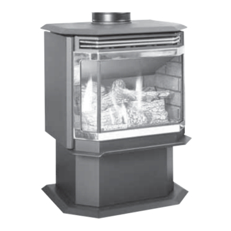
COLUMBIA BAY
DIRECT VENT GAS APPLIANCE
Owner's Manual
Installation and Operation
Model:
COLBAY-FS-B
CAUTION
DO NOT DISCARD THIS MANUAL
• Read, understand and
follow these instructions
for safe installation and
operation.
Quadra-Fire • Columbia Bay • 250-5195 Rev. K
R
• Leave this manual with
party responsible for use
and operation.
WARNING
HOT SURFACES!
Glass and other surfaces are hot during
operation AND cool down.
Hot glass will cause burns.
• Do not touch glass until it is cooled
• NEVER allow children to touch glass
• Keep children away
• CAREFULLY SUPERVISE children in same room as
fi replace.
• Alert children and adults to hazards of high temperatures.
High temperatures may ignite clothing or other fl ammable
materials.
• Keep clothing, furniture, draperies and other fl ammable
materials away.
In the Commonwealth of Massachusetts:
• installation must be performed by a licensed plumber or gas
fi tter.
See Table of Contents for additional Commonwealth of Mas-
sachusetts requirements.
This appliance may be installed as an OEM installation in manufactured
home (USA only) or mobile home and must be installed in accordance
with the manufacturer's instructions and the manufactured home con-
struction and safety standard, Title 24 CFR, Part 3280 or Standard for
Installation in Mobile Homes, CAN/CSA Z240MH.
This appliance is only for use with the type(s) of gas indicated on
the rating plate.
Portland
Tested and
O-T L
Oregon USA
Listed by
C
US
OMNI-Test Laboratories, Inc.
10/08
Advertisement
Table of Contents

Related Manuals for Quadra-Fire Direct Vent Gas Appliance COLBAY-FS-B


Summary of Contents for Quadra-Fire Direct Vent Gas Appliance COLBAY-FS-B
-
Page 1: What To Do If You Smell Gas
• Important operating and maintenance instructions included. WARNING: If the information in these instructions is not followed exactly, a fi re or explosion may result causing property damage, personal injury, or death. • Do not store or use gasoline or other fl am- mable vapors and liquids in the vicinity of this or any other appliance. - Page 2 and Welcome to the Quadra-Fire Family Hearth & Home Technologies welcomes you to our tradition of excellence! In choosing a Quadra-Fire appliance, you have our assurance of commitment to quality, durability, and performance. This commitment begins with our research of the market, including ‘Voice of the Customer’...
-
Page 3: Table Of Contents
Section 1: Listing and Code Approvals A. Appliance Certifi cations ...4 B. Glass Specifi cations ...4 C. BTU Specifi cations ...4 D. High Altitude Installations ...4 E. Non-Combustible Materials ...4 F. Combustible Materials ...4 G. Electrical Codes ...4 H. Requirements for the Commonwealth of Massachusetts ...5 Section 2: Getting Started A. -
Page 4: Section 1: Listing And Code Approvals
Listing and Code Approvals A. Appliance Certifi cation MODEL: Columbia Bay FS LABORATORY: OMNI Test Laboratories, Inc. 061-S-17b-5 TYPE: Direct Vent Gas Heater STANDARD: ANSI Z21.88a-2000 ּ UL307b CAN/CBA 2.17-M91 The product is listed to ANSI standards for “Vented Gas Appliance Heaters”... -
Page 5: Requirements For The Commonwealth Of Massachusetts
NOTE: The following requirements reference various Massachusetts and national codes not contained in this document. H. Requirements for the Commonwealth of Massachusetts For all side wall horizontally vented gas fueled equipment installed in every dwelling, building or structure used in whole or in part for residential purposes, including those owned or operated by the Commonwealth and where the side wall exhaust vent termination is less than seven (7) feet above... -
Page 6: Section 2: Getting Started
Getting Started A. Design & Installation Considerations Quadra-Fire direct vent gas appliances are designed to operate with all combustion air siphoned from outside of the building and all exhaust gases expelled to the outside. No additional air source is required. CAUTION Check building codes prior to installation. -
Page 7: Section 3: Appliance Location & Clearances A. Selecting Appliance Location
Appliance Location and Clearances NOTE: · Illustrations refl ect typical installations and are FOR DESIGN PURPOSES ONLY. · Illustrations/diagrams are not drawn to scale. · Actual installation may vary due to individual design preference. A. Selecting Appliance Location When selecting a location for your appliance it is important to consider the required clearances to walls (see Figure 3.1). -
Page 8: Section 4: Termination Locations
Termination Locations A. Vent Termination Minimum Clearances WARNING Fire Risk. Explosion Risk. Maintain vent clearance to combustibles as specifi ed. • Do not pack air space with insulation or other materials. Failure to keep insulation or other materials away from vent pipe may cause fi re. Measure vertical clearances from this surface. - Page 9 = VENT TERMINAL = 12 inches ... clearances above grade, veran- (See Note 1) da, porch, deck or balcony = 12 inches ... clearances to window or door that may be opened, or to per- manently closed window. (Glass) = 18 inches ... vertical clearance to unventilat- ed soffit or to ventilated soffit lo- cated above the terminal *30 inches ...
-
Page 10: Section 5: Vent Information
Vent Information A. Venting Components In order to comply with applicable codes and product warranties, use only following venting components: • Hearth & Home Technologies (HHT) • Security Chimney's Secure Vent Chimney System • Selkirk Metalbestos • AmeriVent • Simpson Dura-Vent (SDV) FIELD-FABRICATED COMPONENTS. -
Page 11: How To Use The Vent Graph
How to Use the Vent Graph Measure the vertical distance from the center line of the flue pipe to the center of the 90° elbow. On the graph below, draw a horizontal line from that measurement on the vertical axis across until it intersects with the slanted line. -
Page 12: Horizontal Termination
F. Horizontal Termination HHW2 - Recommended for optimum performance. 90 DEGREE ELBOW PIPE LENGTH PIPE LENGTH Figure 5.3 Step 1. Determine the desired location of the appliance. Check to ensure that wall studs or roof rafters are not in the way when the venting system is attached. - Page 13 CENTER LINE WALL THIMBLE Figure 5.5 NOTE: (1) Installation requires a minimum of 6 in. (152mm) horizontal run of vent with a 1/4 in. (6mm) rise run towards the termination. Each 1 ft. (305mm) of horizontal venting must include a 1/4 in. (6mm) rise. Never allow the vent to run downward.
- Page 14 VINYL SIDING APPLY SEALANT TO ALL FOUR SIDES WALL THIMBLE VINYL SIDING COVER STANDOFF WITH SIDING BENEATH WALL THIMBLE REMOVED Figure 5.8 Step 5. Place the wall thimble cover over the pipe assembly and slide the appliance and vent assembly towards the wall, carefully inserting the vent pipe into the vent cap assembly.
-
Page 15: Vertical Termination
G. Vertical Termination 1. Direct Vent Pipe STORM COLLAR FIRESTOP PIPE LENGTH Figure 5.10 Step 1. Check the installation instructions for required 1 in. (25mm) clearances (air space) to combustibles when passing through ceilings, walls, roofs, enclosures, attic rafters, or other nearby combustible surfaces. - Page 16 Step 2. et the gas appliance in its desired location. Drop a plumb bob down from the ceiling to the position of the appliance flue exit, and mark the location where the vent will penetrate the ceiling. Drill a small hole at this point. Next, drop a plumb bob from the roof to the hole previously drilled in the ceiling, and mark the spot where the vent will penetrate the roof.
- Page 17 Step 7. Continue to assemble pipe sections until the height of the vent (before adding the termination cap) meets the minimum code requirements as outlined in the current CAN/CGA-B149 Installation Codes (in Canada), the National Fuel Gas Code NFPA 54/ANSI Z223.1 (in USA), or local codes. Note that for steep roof pitches, the vent height must be increased.
-
Page 18: Cathedral Ceiling
2. Cathedral Ceiling Step 1. Follow installation Steps 1 and 2 under vertical installation section, pages 15-16. Step 2. Remove shingles or other roof covering as necessary to cut the rectangular hole for the support box. Cut the hole 1/8 in. (3mm) larger than the support box outline. - Page 19 3. Class A Metal Chimney EXISTING METAL CHIMNEY SYSTEM DIRECT VENT PIPE Figure 5.21 CAUTION Ensure that existing chimney is functionally sound and clean. • Have inspection done by qualified chimney sweep or professional installer BEFORE converting to direct vent appliance.
-
Page 20: Existing Masonry Chimney
4. Existing Masonry Chimney TOP ADAPTOR RETRO CONNECTOR 90 DEGREE ELBOW DIRECT VENT PIPE Figure 5.25 CAUTION Ensure that existing chimney is functionally sound and clean. • Have inspection done by qualified chimney sweep or professional installer BEFORE converting to direct vent appliance. - Page 21 WARNING Fire Risk. Explosion Risk. • Do not let the fl ex liner sag below the level at which it will connect to the appliance or connector. This could allow hot gas to become trapped and potentially become a fi re hazard. The fl ex liner path should always be sloped up toward the termination cap.
-
Page 22: Section 6: Gas Information
Gas Information A. Fuel Conversions Before making gas connections ensure that the appliance being installed is compatible with the available gas type. Any natural or propane gas conversions necessary to meet the appliance and locality needs must be made by a quali- fi... - Page 23 2. Valve Regulator Replacement WARNING Fire Risk. Explosion Risk. • Disconnect any electrical cords and turn off gas supply to unit before proceeding if converting fuel on an appliance already fully installed. Remove upper and lower back shield. Loosen the set col- lars on the extension rods with the 3/32 in.
-
Page 24: Gas Pressures
B. Gas Pressures Proper input pressures required for optimum appliance per- formance, gas line sizing requirements need to be followed from NFPA54. WARNING Fire Risk. Explosion Hazard. High pressure will damage valve. • Disconnect gas supply piping BEFORE pressure testing gas line at test pressures above 1/2 psig. - Page 25 WARNING Fire or Explosion Hazard • Gas build-up during line purge may ignite. • Purge should be performed by qualifi ed technician. • Ensure adequate ventilation. • Ensure there are no ignition sources such as sparks or open fl ame. •...
-
Page 26: Section 7: Electrical Information
Electrical Information A. Recommendation for Wire See B5 below for recommended maximum lead length (two wire) when using wall thermostat/switch. NOTE: This appliance must be electrically wired and grounded in accordance with local codes or, in the absence of local codes, with National Electric Code ANSI/NFPA 70-latest edition or the Canadian Electric Code, CSA C221.1. - Page 27 IGNITOR ON/OFF SWITCH Figure 7.1 CAUTION Label all wires prior to disconnection when servicing controls. Wiring errors can cause improper and dangerous operation. Verify proper operation after servicing. 10/08 Red 28 in. (711MM) Red 28 in. (711MM) Quadra-Fire • Columbia Bay • 250-5195 Rev. K VALVE CAUTION Shock hazard.
-
Page 28: Section 8: Appliance Setup
Appliance Setup A. Remove Shipping Materials Remove shipping materials from inside or underneath the fi rebox. B. Accessories Install approved accessories per instructions included with accessories. Refer to Section 12 for appropriate accesso- ries. WARNING Shock or fi re risk. Use ONLY optional accessories approved for this appliance. -
Page 29: Positioning The Logs
Figure 8.4 Holding both sides of the metal refractory brick piece, pull slightly together and rotate out of the firebox. INSTALL NEW BRICK SET Figure 8.5 Install rear panel, gently wedging it between sup- port shelf and baffle base. Install the brick brackets that are enclosed with the brick set. -
Page 30: Mineral Wool
Figure 8.9 Place right and left front logs on burner in the grooves provided on the burner surface. Figure 8.10 Place twig over the locator pin on the rear log, gently laying the log across the two front logs. To complete your log set application reinstall the front of the unit. -
Page 31: Blower Installation
H. Blower Installation INCLUDED IN KIT: Blower; 2 female spade wire connec- tors. OOLS REQUIRED: Phillips head screwdriver. Blower motor comes standard with 2 male spade wire connectors. If your appliance has a different connec- tion, use the two female spade wire connectors provided to modify the appliance wiring harness. -
Page 32: Vertical Damper Adjustment
I. Vertical Damper Adjustment Refer to the vent graph on page 11. If your installation falls within the range of the gray shaded area of graph, it may be necessary to make an adjustment to the vertical damper to improve the flame appearance in your appliance. Figure 8.13 The vertical damper adjustment is located on the right side of the unit behind the side curtain. -
Page 33: Section 9: Operating Instructions
Operating Instructions A. Before Lighting Appliance Read this entire manual prior to using the appliance. Failure to follow the instructions may result in property damage, bodily injury, or even death. • Remove all shipping materials from inside and/or underneath the fi rebox. •... -
Page 34: Lighting Appliance
C. Lighting Appliance FOR YOUR SAFETY READ BEFORE LIGHTING FOR YOUR SAFETY READ BEFORE LIGHTING WARNING: If you do not follow these instructions exactly, a fire or explosion may result causing property damage, personal injury or loss of life A. This appliance has a pilot that must be lit manually. When lighting the pilot, follow these instructions exactly. B. -
Page 35: After Appliance Is Lit
D. After Appliance is Lit Initial Break-in Procedure When you light your appliance, you may notice that it pro- duces heat which does have an associated odor or smell. If you feel this odor is excessive it may require the initial three to four hour continuous burn on high followed by a second burn up to 12 hours to fully drive off any odor from paint and lubricants used in the manufacturing process. -
Page 36: Section 10: Troubleshooting
Troubleshooting With proper installation, operation, and maintenance your gas appliance will provide years of trouble-free service. If you do experience a problem, this troubleshooting guide will assist a qualifi ed service person in the diagnosis of a problem and the corrective action to be taken. - Page 37 Symptom Possible Cause 3. (Continued) c. Defective valve. d. Plugged burner orifi ce. e. Wall switch or wires are defective. 4. Frequent pilot outage a. Pilot fl ame may problem. be too high or too low, or blowing (high), causing safety pilot to drop out.
- Page 38 Maintaining and Servicing Your Appliance Although the frequency of your appliance servicing and maintenance will depend on use and the type of installation, a qualifi ed service technician should perform an appliance check-up at the beginning of each heating season. WARNING Risk of injury or property damage.
-
Page 39: Maintenance Tasks
A. Maintenance Tasks Inspect Doors 1. Inspect for scratches, dents or other damage and repair as necessary. 2. Verify no obstructions to air fl ow. 3. Verify maintenance of proper clearance to combustible household objects. Gasket Seal, Glass 1. Inspect gasket seal and its condition. Assembly and Glass 2. -
Page 40: Service And Maintenance Log
B. Service and Maintenance Log Date of Service Performed By Description of Service Page 40 Quadra-Fire • Columbia Bay • 250-5195 Rev. K 10/08... -
Page 41: Section 12: Reference Materials
Reference Materials A. Appliance Dimension Diagram Dimensions are actual appliance dimensions. Use for reference only. For clearances refer to Section 3. Location Figure 12.1 Appliance Dimensions 10/08 Inches Millimeter Location 22-1/2 28-1/2 18-3/4 28-1/2 22-1/2 Quadra-Fire • Columbia Bay • 250-5195 Rev. K Inches Millimeter 11-1/4... -
Page 42: Vent Components Diagram
B. Vent Components Diagram 9-7/16 in. 240 mm 6-5/8 in. 168 mm 7-1/4 in. 184 mm 6-9/16 in. 167 mm SLP6A 6-5/8 in. 168 mm 13-1/4 in. 337 mm 6-9/16 in. 167 mm SLP12 Note: Pipes overlap 1-3/8 inches (34.93 mm) at each joint. Figure 12.2 SLP Series Vent Components Page 42 6-9/16 in. -
Page 43: Vent Components List
C. Vent Components List COMPONENTS SLP-WT-BK Ceiling Support / Wall Thimble, Black SLP-CCS-BK Cathedral Ceiling Support, Black SLP6-BK 6 inch Pipe Length, Black SLP4-BK 9 inch Pipe Length, Black SLP12-BK 12 inch Pipe Length, Black SLP34-BK 24 inch Pipe Length, Black SLP36-BK 36 inch Pipe Length, Black SLP48-BK... -
Page 44: Service Parts List
COLBAY-FS-B Service Parts List Service Parts Diagram Beginning Manufacturing Date: Feb 2005 Columbia Bay Free Standing Ending Manufacturing Date: ______ Log Set Assembly Part number list on following page. Page 44 Quadra-Fire • Columbia Bay • 250-5195 Rev. K 10/08... - Page 45 IMPORTANT: THIS IS DATED INFORMATION. When requesting service or replacement parts for your appliance please provide model number and serial number. All parts listed in this manual may be ordered from an authorized dealer. ITEM DESCRIPTION Log Set Assembly Top Assembly Curtian Side Refractory Assembly Burner Assembly...
-
Page 46: Service Parts
Valve Components IMPORTANT: THIS IS DATED INFORMATION. When requesting service or replacement parts for your appliance please provide model number and serial number. All parts listed in this manual may be ordered from an authorized dealer. ITEM DESCRIPTION Speed Control Knob On/Off Rocker Switch Piezo Ignitor... -
Page 47: Warranty Policy
E. Limited Lifetime Warranty Hearth & Home Technologies LIMITED WARRANTY Hearth & Home Technologies (“HHT”) and its respective brands extends the following warranty for HHT gas, wood, pellet and electric appliances purchased from an authorized HHT dealer and installed in the United States of America or Canada. Warranty starts with date of purchase by the original owner (End User) except as noted for replacement parts. - Page 48 E. Limited Lifetime Warranty (continued) • This limited warranty does not extend to or include surface fi nish on the appliance or terminations, door gasketing, glass gasketing, glass discoloration, fi rebrick, pellet logs, kaowool or other ceramic insulating materials. Rust and/or corrosion on any of the metal surfaces, cast iron components, baffl...
-
Page 49: Contact Information
Please contact your Quadra-Fire dealer with any questions or concerns. For the number of your nearest Quadra-Fire dealer, please visit our web site www.quadrafi re.com SERIAL NUMBER: DATE PURCHASED: DATE INSTALLED: This product may be covered by one or more of the following patents: (United States) 4593510, 4686807, 4766876, 4793322, 4811534, 5000162, 5016609, 5076254, 5113843, 5191877, 5218953, 5263471, 5328356, 5341794, 5347983, 5429495, 5452708, 5542407, 5601073, 5613487, 5647340, 5688568, 5762062, 5775408, 5890485, 5931661, 5941237, 5947112, 5996575, 6006743, 6019099, 6048195, 6053165, 6145502, 6170481, 6237588, 6296474, 6374822, 6413079, 6439226,...