Samsung SMH1713 Series Service Manual
Hide thumbs
Also See for SMH1713 Series:
- User manual (48 pages) ,
- Fast track troubleshooting (4 pages) ,
- User manual (52 pages)

Related Manuals for Samsung SMH1713 Series


Summary of Contents for Samsung SMH1713 Series
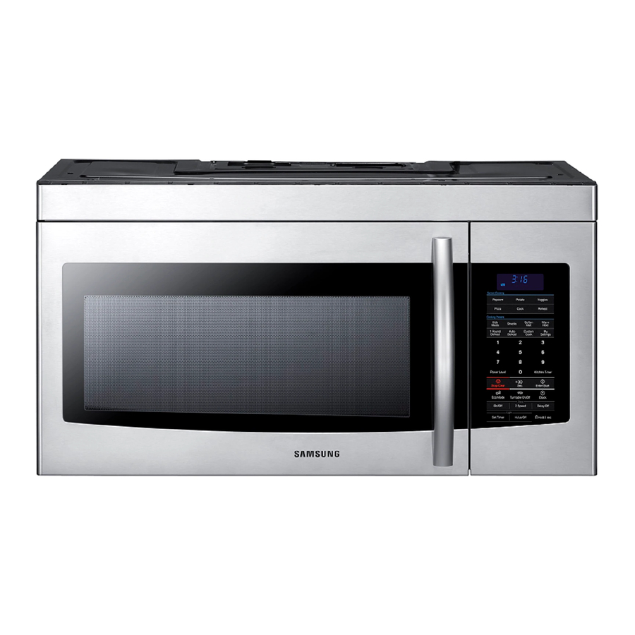
- Page 1 BASIC: 85043 MODEL: SMH1713 MODEL CODE: SMH1713B/XAA SMH1713W/XAA SMH1713S/XAA 1. Precaution 2. Product Specification 3. Disassembly and Reassembly 4. Troubleshooting 5. PCB Diagrams 6. Wiring Diagrams 7. Schematic Diagrams...
-
Page 2: Table Of Contents
• Contents 1. Precaution ................3 1-1 Safety precautions . -
Page 3: Precaution
1. Precaution... -
Page 4: Safety Precautions
1. Precaution Follow these special safety precautions . Although the microwave oven is completely safe during ordinary use, repair work can be extremely hazardous due to possible exposure to microwave radiation, as well as potentially lethal high voltages and currents . 1-1 Safety precautions ( 1. All repairs should be done in accordance with the 13. Design Alteration Warning: Use exact replacement... -
Page 5: Special High Voltage Precautions
1. Precaution 1-2 Special High Voltage Precautions 1. High Voltage Warning Do not attempt to measure any of H. V. Capacitor the high voltages --this includes the filament voltage of the magnetron . High voltage is present during any cook cycle . Before touching any components or wiring, always unplug the oven and discharge the high voltage capacitor (See Figure 1-1) 2. The high-voltage capacitor remains charged about 30... -
Page 6: Specifications
2. Specifications 2-1 Features Product Features • Stirrer and Turntable Continually rotates food to ensure even cooking. • Instant Cook Instant On Controls - Allow quick, one touch cooking and reheating. Two speed, 300CFM venting system - Q uickly removes smoke and • Venting System steam from cook top 2-2 Accessory Item Description Code No. Q’ty TRAY-COOKING DE63-00624A ASSY-GUIDE ROLLER DE92-90495C ASSY-HOOD DAMPER DE92-90242D ASSY-HARD WARE DE92-90505G FILTER-AIR DE63-00666A FILTER-CHARCOAL DE63-00367E... -
Page 7: Table Of Specifications
2. Specifications 2-3 Table of Specifications Basic Model New Model Items 85043 SMH1713 Cavity Size (cu .ft .) 1 .7 1 .7 Power Power Source 120 V / 60 Hz 120 V / 60 Hz Output Power (Watts) 1000 1000 Power Consumption (Watts/Amp) 1580/13 .5 1580/13 .5 Characteristics Control Method Touch... -
Page 8: Disassembly And Reassembly
3. Disassembly and Reassembly 3. Disassembly and Reassembly MAGNETRON, MOTOR ASSEMBLY, VENT BLOWER AND HIGH VOLTAGE TRANSFORMER Oven must be removed from wall. REMOVING OVEN FROM WALL (2 PEOPLE REQUIRED) Disconnect the power cord from the outlet . The oven is hooked on the metal tabs of the wall mounting plate that is secured to the wall . It is not necessary to remove this mounting plate to service this unit . -
Page 9: Replacement Of High Voltage Transformer
3. Disassembly and Reassembly 3-1 Replacement of High Voltage Transformer Parts Explaination Photo Explaination 1. Disconnect oven power . 2. Remove Grille . 1) Remove 3 screws . (Flat Head) 2) S lide the Grille to Grille the left, then pull it straght out . Arrange the screw hole of the Grill with Outer Panel’s when you reassemble the Grill . - Page 10 3. Disassembly and Reassembly 3-1 Replacement of High Voltage Transformer Parts Explaination Photo Explaination 4. Discharge the High voltage capacitor . High voltage capacitor 5. Disconnect all the leads . Base 6. Remove Base Bottom bottom . HV Trans 7. Take out the HV Trans .
-
Page 11: Replacement Of Magnetron
3. Disassembly and Reassembly 3-2 Replacement of Magnetron Parts Explaination Photo Explaination Magnetron generates microwave . Remove the magnetron including the shield case, permanent magnet, choke coils and capacitors . (all of which are contained in one assembly) 1. Disconnect all lead wires from the magnetron . Magnetron 2. Remove nuts (2) securing the magnetron to the wave guide . -
Page 12: Replacement Of Door Assembly
3. Disassembly and Reassembly 3-3 Replacement of Door Assembly Parts Disassembly Photo Explaination 1. Insert flat screwdriver into the gap between Door “A” and Door “C” to remove Door “C” . Be careful when handling Door “C” because it is fragile .Then remove the door assembly . Removal of Door Assembly 2. Insert flat screwdriver into the gap between Door... - Page 13 3. Disassembly and Reassembly 3-3 Replacement of Door Assembly Removal of 4. Remove 2 screws, then handle is detached from Handle Door “A” . 5. Following the procedure as shown in the figure, insert and bend a thin metal plate between Door Removal of “E” and Door “A” until you hear the ‘tick’ sound . Door “E”...
-
Page 14: Replacement Of Fuse
3. Disassembly and Reassembly 3-4 Replacement of Fuse Parts Explaination Photo Explaination 1. Disconnect oven power . 2. Remove Grille . 1) Remove 3 screws . (Flat Head) Grille 2) S lide the Grille to the left, then pull it straght out . Arrange the screw hole of the Grill with Outer Panel’s when you reassemble the Grill . -
Page 15: Replacement Of Drive Motor
3. Disassembly and Reassembly 3-5 Replacement of Drive Motor Parts Explaination Photo Explaination 1. Disconnect power and remove bottom plate screws(5) . 2. Remove bottom plate and disconnect the turntable motor drive . Drive 3. Remove turntable motor screws(1) and pull Motor the turntable motor out . 4. When replacing the drive motor, be sure to remount it in the correct position with the coupler . -
Page 16: Replacement Of Control Circuit Board
3. Disassembly and Reassembly 3-7 Replacement of Control Circuit Board Parts Explaination Photo Explaination 1. Disconnect power and remove grille . 2. Be sure to ground any static electric charge in your body and never touch the control circuit . Removal of Control Box 3. Remove a screw securing the control box Assembly assembly . -
Page 17: Replacement Of Cooktop Lamp
3. Disassembly and Reassembly 3-8 Replacement of Cooktop lamp When replacing the night light, make sure that you are wearing gloves to avoid injury from the heat of the bulb . Parts Explaination Photo Explaination Cooktop lamp is on the bottom of the set . 1. Unplug the oven or turn off the power at the main power . -
Page 18: Replacement Of Oven Light
3. Disassembly and Reassembly 3-9 Replacement of Oven Light Parts Explaination Photo Explaination 1. Remove the Grille 2. Remove the COVER LAMP by push Oven Light the hook and put up the lever . 3. Replace the bulb with a 40 watt appliance bulb . -
Page 19: Troubleshooting
4. Troubleshooting 4. Troubleshooting 4-1 Parts checking method Parts Photo Good No Good Fuse 0 .1 ~ 1 Ω 100 MΩ exceed T .C .O 0 .1 ~ 1 Ω 100 MΩ exceed 1 ~ 9 Ω H .V Trans 100 MΩ exceed 100 ~ 990 Ω Convection 100 MΩ... -
Page 20: Error Code Numbering Rule
4. Troubleshooting 4-2 Error Code Numbering Rule 1. ERROR CODE NUMBERING RULE is applied to a microwave oven and an oven .(CMO, OTR, Grill, Convection, Commercial etc .) 2. All sensors and devices have their own number . ex) Gas Sensor = 1, Temp . Sensor = 2, . . . 3. Of each device, No .1 and No .2 refer to “Open Error”... - Page 21 4. Troubleshooting Weight Sensor Error Gas Sensor Error Case (E-1X) Solution Page Code 22 Page E-31 Open (When value of HEX is above “FF” for 5 seconds) 23 Page E-32 Short In case the initial value of HEX is under “14” for 30 E-33 seconds while a weight sensor in operation . Check Sensor .
-
Page 22: Electrical Malfunction
4. Troubleshooting 4-4 Electrical Malfunction 4-4-1 E-11, E-21, E-27, E-29, E-2B, E-31, E-32, E-41, E-46, E-61 Sensor Open Error (E-11, E-21, E-27, E-29, E-2B, E-31, E-32, E-41, E-46, E-61) : Check if the sensor housing is inserted into the connector Connect the sensor. of the main PCB. Is the sensor disconnected? sensor Is the sensor wire Connect the : Check if the sensor wire is damaged, if the connected properly? - Page 23 4. Troubleshooting 4-4-2 E-12, E-22, E-28, E-32, E2A, E-2C ,E-42, E-2C, E-42 or E-62 Sensor Short Error (E-12, E-22, E-28, E-32, E2A, E-2C, E-42, or E-62) : Check if both terminals of the sensor are slightly shorted. Remove the shorted part Is the sensor shorted? of the temperature sensor. sensor : Check if the sensor and related parts such as the connector or Is the sensor terminal part Remove any foreign...
- Page 24 4. Troubleshooting 4-4-3 E-13, E-14, E-43, E-44, E-63 Sensor Max Time Error (E-13, E-14, E-43, E-44, E-63) Does it heat up without Insert food : Since heating without placing food into placing food into it? and heat it again. the oven may damage the product, take care. Does it heat with completely Place food with : Since heating completely dried food...
- Page 25 4. Troubleshooting 4-4-4 -SE- Key Short Error (- SE -) Is the key not recognized at all? Is the key recognized intermittently? Is a specific key not recognized? The membrane is defective. S/W Error Replace the Control Panel. After Power > On, does the symptom continue? Replace the PCB.
- Page 26 4. Troubleshooting 4-4-5 E-33, E-34 or E-35 Weight Sensor Error (E-33, E-34 or E-35) Has the turntable been placed over the roller properly? Place the turntable over the roller properly. Is the weight sensor Remove the foreign contaminated by any foreign substance. substance? Does the roller turn Place the food : Check if the turntable turns abnormally and press against the...
- Page 27 4. Troubleshooting 4-4-6 E-36 or E-47 Door Open Error(PH-Sensor, Weight Sensor), (E-36 or E-47) Was the door open during Close the door. the operation? Check the Door S/W : Check the housing connected to Is the door sensing part normal? and the housing. the door S/W and PCB and if it is opened or shorted intermittently.
- Page 28 4. Troubleshooting 4-4-7 E-45 Cooling Error (E-45) : To remove moisture from the sensor, open the door for 5 minutes. Remove any moisture Is the sensor wet? of the sensor. sensor : Check if the GND and sensor terminal Check the sensor Is the sensor voltage over 3V? is maintained over 3V continuously during terminal and housing.
- Page 29 4. Troubleshooting 4-4-8 E-51, E-53 or E-54 EEPROM Error (E-51, E-53, or E-54) Insert and solder : An R4LCO40 or 24LCO4 EEPROM EEPROM이 삽입 되었는가? Has the EEPROM been inserted? an EEPROM is to be used. Check if a proper EEPROM has been installed. Replace the Is the EEPROM terminal opened or EEPROM 단자가...
- Page 30 4. Troubleshooting 4-4-11 E-0b, E-2b, E-2C, 0t Cooling Fan Motor Sensor Error (E-0b, E-2b, E-2C, Ot) Is the temperature An “E-2b” error sensor of the PCB open? occurred. Insert the Was there a short- temperature sensor. circuit in the temperature An “E-2C, 0t” error occurred. sensor of the PCB? Repair the short circuit.
- Page 31 4. Troubleshooting 4-4-12 E-23, E-26 Preheating Error (E-08, E-23, E-26) : Check the voltages of both heater terminals. Check the heater Does the heater work? related drive part. Heater terminal Replace the Is the heater temperature heater. very low? : After operating the heater for more then 10 minutes check if the heater temperature remains low.
- Page 32 4. Troubleshooting 4-4-13 E-02, E-03, E-04 or E-05 Cooling Time Over Selection Error (E-02, E-03, E-04, or E-05) Is this happening during the MW operation? Is it happening during the Grill operation? Over Time is Over Time is set? set? Is it happening during the Convection operation? An “E-03”...
- Page 33 4. Troubleshooting 4-4-14 E-24 Oven Temperature Error (E-24) “E-09, E-24, E-0A” 가 표시된다 Is the oven internal temperature An “E-09” error maintained over 320 degrees? occurred. Has the oven internal temperature An “E-24, E-0A” error reached over 350 degrees? occurred. Reconnect the Is the temperature sensor temperature connectivity normal?
- Page 34 4. Troubleshooting 4-4-15 E-25 Initial Temperature Error (at MW mode), (E-25) Is the oven in MW mode? An “E-25” error Is the internal temperature occurred. over 200 degrees? Press the Cancel key. Press the Cancel key to cancel the current state. Connect it Is the sensor connectivity properly normal?
- Page 35 4. Troubleshooting 4-4-16 E-06 Swing Heater Detection Error (E-06) Is the oven in Bake Toast mode? Has the switch heater After waiting for 20 seconds, check if the micro-switch has operated for 20 seconds? been detected. The micro-switch is Has the micro-switch defective Replace it.
- Page 36 4. Troubleshooting 4-4-17 If oven malfunction *Inspection method Oven does not operate. Is Primary interlock Is Fuse OK? switch normal? Is Power Relay normal? Is the magnetron Replace switch temperature switch normal? Power supply circuit check point Do check power supply Is SMPS power supply cirduit normal? circuit Do check...
- Page 37 4. Troubleshooting 4-4-18 If button malfunction Buttons of the control panel do not work. *Inspection method Are button pressed Refer to User Manual in the correct order? Tact type Is the connector of the control panel normal? Replace PCB. Menbrane type...
- Page 38 4. Troubleshooting 4-4-19 If food is not heated even though an oven works *Inspection method Food is not heated even though an oven works. Is the latch switch Method to control latch switch operating normally? Checking high voltage circuits...
-
Page 39: Pcb Diagrams
5. PCB Diagrams 5-1 PCB Diagrams (This Document can not be used without Samsung’s authorization) -
Page 40: Pcb Diagrams
5. PCB Diagrams 5-2 PCB Diagrams (This Document can not be used without Samsung’s authorization) -
Page 41: Wiring Diagrams
6. Wiring Diagrams 6. Wiring Diagrams 6-1 Wiring Diagrams (This Document can not be used without Samsung’s authorization) - Page 42 6. Wiring Diagrams 6-1 Wiring Diagrams (This Document can not be used without Samsung’s authorization)
-
Page 43: Schematic Diagrams
7. Schematic Diagrams 7-1 Schematic Diagrams (This Document can not be used without Samsung’s authorization) TR207 KRC246 TR206 KRC246 TR205 KRC246 TR211 KRC246 TR210 KRC246 TR209 KRC246 TR212 KRC246 IC101 TMP86CM72FG-CHUN,MH3 R708 R709 R710 R711 R712 R713 R714 DSP101 VFD25-0717... - Page 44 .samsungportal .com Latin America latin .samsungportal .com cis .samsungportal .com Europe europe .samsungportal .com China china .samsungportal .com Asia asia .samsungportal .com Mideast & Africa mea .samsungportal .com © Samsung Electronics Co ., Ltd . June . 2011 Printed in Korea...