Samsung SMH1622B/XAA Installation Instructions Manual
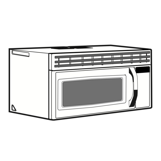
Over the range microwave oven
Hide thumbs
Also See for SMH1622B/XAA:
- Installation instructions manual (20 pages) ,
- User manual (6 pages)
Table of Contents
Advertisement
Installation Instructions
Over the Range Microwave Oven
BEFORE YOU BEGIN
IMPORTANT
Save these instructions for local inspector's use.
IMPORTANT
Observe all governing codes and ordinances.
• Note to Installer
• Note to Consumer
• Skill level
• Proper installation is the responsibility of the installer.
• Product failure due to improper installation is not covered under the Warranty.
READ CAREFULLY. KEEP THESE INSTRUCTIONS.
SMH8165_XAA DE68-03587A-04-EN_120725.indd 1
(Read these instructions completely and carefully.)
- B e sure to leave these instructions with the Consumer.
- K eep these instructions for future reference.
- I nstallation of this appliance requires basic mechanical and electrical skills.
2012-07-25
8:05:23
Advertisement
Table of Contents

Related Manuals for Samsung SMH1622B/XAA


Summary of Contents for Samsung SMH1622B/XAA
-
Page 1: Installation Instructions
Installation Instructions Over the Range Microwave Oven BEFORE YOU BEGIN (Read these instructions completely and carefully.) IMPORTANT Save these instructions for local inspector’s use. IMPORTANT Observe all governing codes and ordinances. • Note to Installer - B e sure to leave these instructions with the Consumer. • Note to Consumer - K eep these instructions for future reference. -
Page 2: Table Of Contents
Contents General information Step-by-step installation guide Important safety instructions....... 3 1. Placement of the mounting plate .... 8 A. Removing the microwave oven from the Electrical requirements ........ 3 carton/removing the mounting plate ..8 Hood exhaust ..........4 B. Finding the wall studs ........ 8 Damage – Shipment/Installation .... -
Page 3: General Information
General information ImPORTANT SAFETY INSTRUCTIONS This product requires a three-prong grounded The power cord of this outlet. The installer must perform a ground appliance is equipped continuity check on the power outlet box before with a three-prong beginning the installation to insure that the (grounding) plug which outlet box is properly grounded. If not properly mates with a standard grounded, or if the outlet box does not meet three-prong (grounding) electrical requirements noted (under ELECTRICAL... -
Page 4: Hood Exhaust
General information HOOD EXHAUST NOTE: Read these next two pages only if you plan to vent your exhaust to the outside. If you plan to recirculate the air back into the room, proceed to page 11. OUTSIDE TOP EXHAUST (EXAmPLE ONLY) The following chart describes an example of one possible ductwork installation. EqUIVALENT NUMBER EqUIVALENT DUCT PIECES LENGTH USED LENGTH Roof Cap 24 ft. 24 ft. 12 ft. Straight Duct 12 ft. 12 ft. (6˝ Round) Rectangular-to- Round Transition 5 ft. 5 ft. Adaptor* Equivalent lengths of duct pieces are based on actual tests and reflect requirements for good venting performance with Total Length 41 ft. - Page 5 General information maximum duct length: NOTE: If you need to install ducts, note that the total duct length of 3 ¼˝ x 10˝ rectangular or 6˝ diameter For satisfactory air movement, the total duct length of round duct should not exceed 140 equivalent feet. 3 ¼˝ x 10˝ rectangular or 6˝ diameter round duct should Outside ventilation requires a HOOD EXHAUST DUCT. not exceed 140 equivalent feet. Read the following carefully. Elbows, transitions, wall and roof NOTE: It is important that venting be installed using caps, etc., present additional resistance to airflow the most direct route and with as few elbows as and are equivalent to a section of straight duct which is possible. This ensures clear venting of exhaust and longer than their actual physical size. When calculating...
-
Page 6: Damage - Shipment/Installation
General information DAmAGE – SHIPmENT/INSTALLATION • If the unit is damaged in shipment, return the unit to the store in which it was bought for repair or replacement. • If the unit is damaged by the customer, repair or replacement is the responsibility of the customer. • If the unit is damaged by the installer (if other than the customer), repair or replacement must be made by arrangement between customer and installer. -
Page 7: Tools You Will Need
General information TOOLS YOU WILL NEED #1 and #2 Phillips Pencil Ruler or tape measure and Carpenter square (optional) screwdriver straight edge Tin snips (for cutting Scissors (to cut Electric drill with ˝, ½˝ and Filler blocks or scrap wood damper, if required) template, if necessary) ⅝˝ drill bits pieces, if needed for top cabinet spacing (used on recessed bottom cabinet... -
Page 8: Step-By-Step Installation Guide
Step-by-step installation guide 1. PLACEmENT OF THE mOUNTING PLATE A. REmOVING THE B. FINDING THE WALL STUDS mICROWAVE OVEN FROm THE CARTON/REmOVING THE mOUNTING PLATE Wall Studs 1. Remove the installation instructions, Exhaust adaptor, filters, glass tray and the small hardware bag. Do not remove the Styrofoam Center protecting the front of the oven. 2. Fold back all 4 carton flaps fully against carton sides. Then carefully roll the oven and carton over onto the top side. The oven should be 1. Find the studs, using one of the following resting in the Styrofoam. -
Page 9: Determining Wall Plate Location Under Your Cabinet
Step-by-step installation guide C. DETERmINING WALL PLATE LOCATION UNDER YOUR CABINET Plate position – beneath flat bottom cabinet Plate position – beneath framed recessed cabinet bottom 16-1/2 ² 16 ½˝ Draw a vertical line on the wall at the center of the 30˝ 30˝ to Cooktop At least 30˝ wide space. Tape the Rear Wall Template Draw a vertical line on the wall at the center of the 30˝ onto the wall matching the space. centerline and touching the Tape the Rear Wall Template onto the wall matching bottom of the cabinet. -
Page 10: Aligning The Wall Plate
Step-by-step installation guide D. ALIGNING THE WALL PLATE Draw a Vertical Line Centerline Hole A on Wall from Center notches of Top Cabinet Horizontal Line Area E Hole C Hole B Horizontal Line Draw a Horizontal line on wall from bottom of “Rear Wall Template˝. CAUTION: Wear gloves to avoid cutting fingers on sharp edges. 1. Draw a Vertical line on the wall at the center NOTE: Holes A, B and C are inside area E. of the 30˝ wide space. If none of A, B and C is in a stud, find a stud somewhere in area E and draw a forth circle to 2. Draw a Horizontal line on the wall at the line up with the stud. -
Page 11: Ventilation Types (Choose A, B Or C)
Step-by-step installation guide 2. VENTILATION TYPES (CHOOSE A, B OR C) This microwave oven is designed for adaptation to the NOTE: This microwave is shipped assembled for following three types of ventilation: Outside Top Exhaust (except for non-vented models). And exhaust adaptor is shipped assembled to the A. Outside Top Exhaust (Vertical Duct) filler-upper. Select the type of ventilation required for B. Recirculating (Non-Vented Ductless) your installation and proceed to that section. C. Outside Back Exhaust (Horizontal Duct) A. OUTSIDE TOP EXHAUST B. RECIRCULATING (VERTICAL DUCT) (NON-VENTED DUCTLESS) Adaptor in Place for Outside Top Exhaust See page 12 See page 13 A Charcoal Filter Accessory Kit is required for the nonvented exhaust. (See your Owner’s Manual for the... -
Page 12: Outside Top Exhaust (Vertical Duct)
Step-by-step installation guide A. OUTSIDE TOP EXHAUST (VERTICAL DUCT) A1. INSTALLATION PROCEDURE NOTE: The house duct is needed to connect to the exhaust adaptor after installation completion. FOR EXHAUST ADAPTOR AND PROPER DAMPER OPERATION House Duct CHECK Exhaust Adaptor and Damper is shipped assembled to the filler-upper. 1. Slide exhaust adaptor following the instructions show in diagram. 2. Make sure tape securing damper is removed and damper pivots easoly before mounting microwave. -
Page 13: Recirculating (Non-Vented Ductless)
Step-by-step installation guide B. RECIRCULATING (NON-VENTED DUCTLESS) B1. ADAPTING mICROWAVE BLOWER 5. Place the blower unit back into the opening. FOR RECIRCULATION 2. Lift up the blower plate. CAUTION: Do not pull or stretch the blower unit Back of wiring. Make sure the wires are not pinched. Microwave 6. Secure blower unit to microwave with the screw. 1. Remove and save screw that holds blower plate to microwave. -
Page 14: Outside Back Exhaust (Horizontal Duct)
Step-by-step installation guide C. OUTSIDE BACK EXHAUST (HORIzONTAL DUCT) C1. ADAPTING mICROWAVE BLOWER 5. Place the blower unit back into the opening. FOR OUTSIDE BACK EXHAUST AFTER: Fan Blade Openings Facing Back 1. Remove and save screw that holds blower Plate End A to microwave. Screw End B 2. Lift up the Blower Plate. Blower Motor Back of Microwave CAUTION: Do not pull or stretch the blower unit wiring. Make sure the wires are not pinched. Blower Plate Screw NOTE: The blower unit exhaust openings 3. Carefully pull out the blower unit. The wires will should match exhaust openings on rear of extend far enough to allow you to adjust the microwave oven. -
Page 15: Installation
Step-by-step installation guide 3. INSTALLATION INSTALLATION OVERVIEW A. Prepare Rear Wall (only horizontal duct) B. Attach Mounting Plate to Wall C. Prepare Top Cabinet D. Mount the Microwave Oven E. Connecting Ductwork (only vertical duct) A. PREPARING THE REAR B. ATTACH THE mOUNTING WALL FOR OUTSIDE BACK PLATE TO THE WALL EXHAUST You need to cut an opening in the rear wall for outside exhaust. Attach the plate to the wall using toggle bolts. At least one wood screw must be used to attach the plate to a wall stud. -
Page 16: Use Top Cabinet Template For Preparation Of Top Cabinet
Step-by-step installation guide B. ATTACH THE mOUNTING D. mOUNT THE mICROWAVE PLATE TO THE WALL (CONT.) OVEN To use toggle bolts: Spacing for Toggles more Than Wall Thickness Toggle Wings Mounting Toggle Plate Bolt FOR EASIER INSTALLATION AND PERSONAL SAFETY, WE RECOMMEND THAT TWO PEOPLE INSTALL THIS MICROWAVE OVEN. Wall Bolt End ImPORTANT: Do not grip or use handle during 3. Place the mounting plate against the wall and installation. insert the toggle wings into the holes in the wall NOTE: If your cabinet is metal, use the nylon to mount the plate. grommet around the power cord hole to prevent NOTE: Before tightening toggle bolts and wood cutting of the cord. -
Page 17: Connecting Ductwork For Outside Top Exhaust
Step-by-step installation guide D. mOUNT THE mICROWAVE E. CONNECTING DUCTWORK OVEN (CONT.) FOR OUTSIDE TOP EXHAUST Cabinet Front House Duct Cabinet Bottom Shelf Filler Block Equivalent to Depth of Cabinet Recess Self-Aligning Screw Microwave Oven Top 4. Attach the microwave oven to the top cabinet. Insert the 2 self-aligning screws 1. Extend the house duct down to connect to the through the cabinet bottom shelf and exhaust adaptor. -
Page 18: Before You Use Your Microwave
Before You Use Your Microwave BEFORE YOU USE YOUR mICROWAVE Read the Owner’s Manual. Make sure the microwave oven has been installed according to instructions. Keep installation instructions for the local inspector’s use. Remove all packing material from the microwave oven. 3. Install turntable and ring in cavity. Replace house fuse or turn breaker back on. 5. Plug power cord into a dedicated 15 amp electrical outlet. - Page 19 Note SMH8165_XAA DE68-03587A-04-EN_120725.indd 19 2012-07-25 8:05:33...
- Page 20 Code No.: DE68-03587A-04 SMH8165_XAA DE68-03587A-04-EN_120725.indd 20 2012-07-25 8:05:33...