Rinnai RHFE-950ETR Operation & Installation Manual
Power flued flamefire gas space heater
Hide thumbs
Also See for RHFE-950ETR:
- Operation & installation manual (32 pages) ,
- Installation manual (24 pages)
Table of Contents
Advertisement
Quick Links
OPERATION & INSTALLATION MANUAL
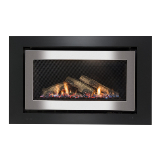
Power Flued Flamefire
Gas Space Heater RHFE-950ETR
This appliance shall be installed in accordance with:
• Manufacturer's Installation Instructions
• Current AS/NZS 5601 AS/NZS 3000
• Local Regulations and Municipal Building Codes including local OH&S requirements
This appliance must be installed, maintained and removed by an Authorised Person.
All Rinnai gas products
For continued safety of this appliance it must be installed and maintained in
are A.G.A. certified.
accordance with the manufacturers instructions.
Advertisement
Chapters
Table of Contents

Related Manuals for Rinnai RHFE-950ETR


Summary of Contents for Rinnai RHFE-950ETR
- Page 1 OPERATION & INSTALLATION MANUAL Power Flued Flamefire Gas Space Heater RHFE-950ETR This appliance shall be installed in accordance with: • Manufacturer’s Installation Instructions • Current AS/NZS 5601 AS/NZS 3000 • Local Regulations and Municipal Building Codes including local OH&S requirements This appliance must be installed, maintained and removed by an Authorised Person.
- Page 2 Congratulations on the purchase of your Rinnai RHFE-950ETR Flamefire. We trust you will have many years of comfort and enjoyment from your appliance. BEFORE PROCEEDING WITH THE OPERATION OR INSTALLATION OF YOUR NEW HEATER PLEASE READ THIS MANUAL THOROUGHLY AND GAIN A FULL UNDERSTANDING OF THE REQUIREMENTS, FEATURES AND OPERATION OF YOUR NEW APPLIANCE.
-
Page 3: Table Of Contents
INSTALLATION REQUIREMENTS ........................4 CERTIFICATION .............................. 4 FLUE INSTALLATION MANUAL ........................4 CARTON CONTENTS / ITEM CHECKLIST ..................... 4 ABOUT YOUR NEW RHFE-950ETR SPACE HEATER.............. 5 GENERAL DESIGN LAYOUT........................... 5 REMOTE CONTROL GENERAL LAYOUT ...................... 6 REMOTE CONTROL DISPLAY........................7 FEATURES............................... -
Page 4: Before You Start
Please keep these instructions in a safe place for future reference. FLUE INSTALLATION MANUAL These instructions are to be used in conjunction with the Rinnai “Power Flued Flamefire Space Heater Co-axial Flue System Installation Manual” supplied with flue kits ASPDFK or ASPKIT03. -
Page 5: About Your New Rhfe-950Etr Space Heater
ABOUT YOUR NEW RHFE-950ETR SPACE HEATER GENERAL DESIGN LAYOUT CONTROL PANEL DETAIL ROOM AIR RETURN / ERROR DISPLAY INLET FILTERS GLAZED FLAME WINDOW Displays error codes (located behind Dust filter meshing is fixed to the fascia and viewed through grill). -
Page 6: Remote Control General Layout
ABOUT YOUR NEW RHFE-950ETR SPACE HEATER REMOTE CONTROL GENERAL LAYOUT FRONT REAR STANDBY / ON BUTTON Stops and Operates the heater remotely. Lock Override Extra Low Flame CONTROL BUTTONS Used to select the temperature, Temperature Time flame picture and adjust timers. -
Page 7: Remote Control Display
ABOUT YOUR NEW RHFE-950ETR SPACE HEATER REMOTE CONTROL DISPLAY MAIN DISPLAY OVERRIDE INDICATOR Displays current Clock, Timer or Displays when Override has been Temperature status. selected. MAIN DISPLAY MODE EXTRA LOW INDICATOR Indicates that controller is in Time Displays when Extra Low function or Temperature display modes. -
Page 8: Safety
Young children should be supervised to ensure they do not play with the appliance. g. If the supply cord is damaged or requires replacing, it must be replaced by the manufacturer or the manufacturer's agent or similarly qualified person in order to avoid a hazard. Rinnai Australia Operation Manual... - Page 9 This effect may be amplified if the air in the room contains cooking vapours or cigarette smoke. To avoid this possibility, it is recommended that a mat be placed in front of the appliance, extending at least 750 mm in front of it. Rinnai Australia Operation Manual...
-
Page 10: Basic Heater Operation
NOTE time. To re-activate the remote control press any button on the keypad. This returns the display to the previous mode. No information is transmitted from the controller to the heater when re-activating the display. Rinnai Australia Operation Manual... -
Page 11: Turning On The Power
The Temperature Can Be Pre-set To: A.L (Low) – Continuous combustion on low. B.16°C ~ 26°C (in 1°C steps) – Thermostatic control to pre-set temperature selected. Combustion rate varies to maintain the selected temperature. C.H (High) – Continuous combustion on high. Rinnai Australia Operation Manual... -
Page 12: Flame Function
Should the room temperature reach 40°C whilst the flame function is activated the heater will switch off automatically. This is a safety feature. NOTE Lock OverrideAuto Off Flame Temperature Time Timer 1 Set ON OFF Timer 2 Set ON OFF Rinnai Australia Operation Manual... -
Page 13: Programmed Heater Operation
Remote Control Display When operated by the Timer(s) the Flame Function is not available. If desired the flame picture can be controlled by raising or lowering the set NOTE temperature. Rinnai Australia Operation Manual... -
Page 14: Pre-Heat
The Remote Control Display will show "Lock" in the top left hand corner. Temperature Time Timer 1 Set ON OFF To cancel the Lock function hold down the Lock button for 3 seconds. Timer 2 Set ON OFF Rinnai Australia Operation Manual... -
Page 15: Care And Maintenance
Receiver Window will illuminate RED and the combustion state reduces to front burner, low operation only. To restore normal operation remove the obstruction and use the remote control to resume normal heater operation. Rinnai Australia Operation Manual... -
Page 16: General Heater Characteristics
SERVICE Rinnai recommend that this appliance and installation be inspected and serviced every 2 years. If the power supply cord or any other component of the heater are damaged, they must be replaced by Rinnai or a suitably qualified person. -
Page 17: Trouble Shooting Checklist
ERROR CODES Your Rinnai space heater is also fitted with self diagnostic electronics that monitor the appliance during start-up and operation. Should a fault occur the heater will shut down, the fault that has caused the shut down will be indicated by a pair of flashing digits in the Error Display window and a ‘RED’... -
Page 18: Installation Manual
INSTALLING THE DRESS GUARD & INNER FASCIA PANEL ............28 INSTALLATION AND COMMISSIONING CHECKLIST ................. 29 10. INSTALLATION RECORD ........................29 11. FINAL CHECKLIST ..........................29 WIRING DIAGRAM ........................30 INSTALLATION NOTES ......................31 CONTACT INFORMATION......................32 Rinnai Installation Manual... -
Page 19: Installation General
INSTALLATION GENERAL PRODUCT SPECIFICATIONS Model: RHFE-950ETR General description: Inbuilt Fan Exhaust Balanced Flued Convection Flame Fire with Electronic Temperature Control, Timer and Remote. Gas input rate: Natural Gas Propane Low (MJ/hr): High, Extended flue / Direct flue (MJ/hr): 31/34 32/34 Gas control: Manual On/Off, 3 Heat Settings (electrical touch control). -
Page 20: Heater Location
ENCLOSURE REQUIREMENTS The Rinnai RHFE-950ETR has a cool outer casing allowing it to be installed into existing Masonry fireplace or into a decorative fireplace constructed from combustible materials such as wood or plaster. For all installations, ONLY Rinnai ASP & ES Flue components MUST BE used. The Rinnai RHFE- 950ETR MUST NOT be flued into ‘natural draft’... -
Page 21: Gas Supply
This heater has a power cord with a three pin plug supplied. The power cord passes through the gap at the rear left of the appliance. Rinnai recommend the heater be plugged into a 240V, 10A earthed power point. The power point must be a maximum of 1500 mm to the side of the heater (it must not be above the heater). -
Page 22: Flue Installation
FLUE INSTALLATION TYPES OF FLUE INSTALLATIONS Consult the Rinnai “Power Flued Flamefire Space Heater Co-axial Flue System Installation Manual” supplied with flue kits ASPDFK or ASPKIT03 for detailed flue installation instructions. IMPORTANT Use only Rinnai RHFE-950ETR flue components with this appliance. -
Page 23: Flue Terminal Location
FLUE INSTALLATION FLUE TERMINAL LOCATION The flue terminal should be positioned away from flammable materials. The RHFE-950ETR flue terminal is ‘Fan Assisted’ with a maximum input of WARNING 34 MJ/h Ensure that the location of the flue terminal can comply with the requirements of AS/NZS 5601 - Fig. -
Page 24: Heater Installation
The heater does not come supplied with flue components. These are purchased separately. ONLY the specified Rinnai flue components MUST be used with this appliance. IMPORTANT Connections between the heater and the flue system MUST BE made in accordance with the Rinnai “Power Flued Flamefire Space Heater Co-axial Flue System Installation Manual”... -
Page 25: Securing The Engine
Remove the four retaining screws that secure the combustion chamber glass panel to the heater engine. Then Rotate and lift the combustion chamber glass clear of the combustion chamber. Place both glass and screws in a safe location until required. Rinnai Australia Installation Manual... - Page 26 Confirm the correct location of all the logs Fit the log to slot in the middle of the burner box before proceeding with the placement of the and onto the pin of log as shown. granular burner medium. Rinnai Australia Installation Manual...
- Page 27 ¼ of a turn to ensure the combustion chamber class retaining springs are engaged. To test this gently pull the top of the glass frame forward and release, a correctly fitted the glass will spring firmly back into place and seal the combustion chamber. Rinnai Australia Installation Manual...
-
Page 28: Commissioning
Rotate the bottom of the inner fascia in towards the engine body allowing the magnets to secure both the inner fascia and the dress guard to the heater engine. Rinnai Australia Installation Manual... -
Page 29: Installation And Commissioning Checklist
1. Appliance positioned in a suitable location (clearances, combustible clearances, mantels & surrounds, etc.). 2. Is a Rinnai approved flue system installed & tested in accordance with the instructions? 3. Gas pressure checked and set? 4. Has the burner media been installed as per instructions? 5. -
Page 30: Wiring Diagram
4 3 2 1 3 2 1 bl w y bk bk bk bk y pl gy or y or bk br bl w 8 6 3 4 1 Rear Burner Rear Burner REARB Pilot Front Burner Rinnai Australia Installation Manual... -
Page 31: Installation Notes
INSTALLATION NOTES Rinnai Australia Installation Manual... -
Page 32: Contact Information
Braeside, Victoria 3195 For further information visit: www.rinnai.com.au Rinnai has a Service and Spare Parts network with personnel who are fully trained and equipped to give the best service on your Rinnai appliance. If your appliance requires service, please call our National Help Line. Rinnai recommends that this appliance be serviced every 2 years.