Yanmar 1GM Operation Manual
Diesel engine
Hide thumbs
Also See for 1GM:
- Shop manual (241 pages) ,
- Shop manual (241 pages) ,
- User manual (240 pages)
Advertisement
Quick Links
Advertisement

Related Manuals for Yanmar 1GM


Summary of Contents for Yanmar 1GM
- Page 2 This may result in some discrepancies in the contents of this manual. This manual is concerned with the 2 cylinder model. Although the 1GM, 3GMD and 3HM seem to be different on the outside, their handling is the same.
- Page 3 In order to deliver correct parts to you, we need accurate data on the engine you purchased. The information needed is described in the illustrations below. For ready reference, please record the information in the spaces provided under the illustrations.
-
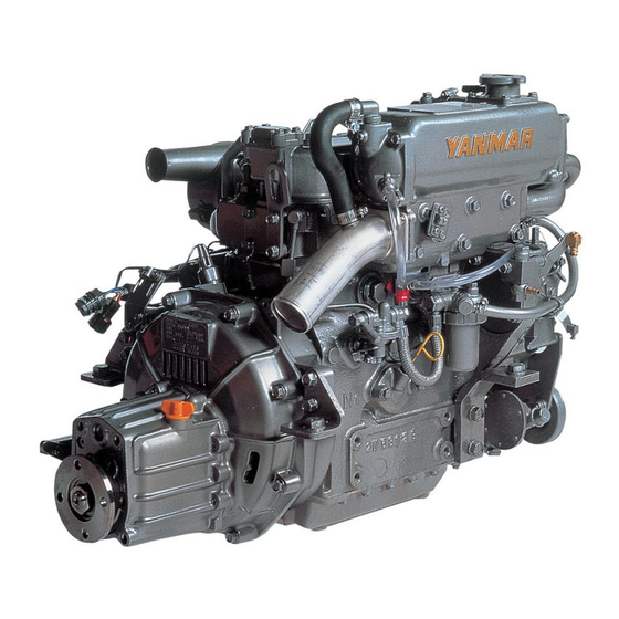
Page 5: Name Of Parts
I. Name of parts 1 Reduction and reversing gear 2 Output shaft coupling 3 Clutch control lever 4 Installation foot 5 Engine tube oil dipstick 6 Clutch tube oil dipstick/Supply port 7 Cooling water pump 8 Fuel feed pump 9 Exhaust manifold 10 Mixing elbow 11 Air intake silencer 12 Alternator... -
Page 7: Engine Installation
[3-3.1 Engine installation 1) For the engine installation, be sure to use the flexible rubber mount. Yanmar prepared the flexible mounts which match the respective engine characteristics as a standard accessory. 1. Lock Nut 2. - Page 8 Note Avoid splashing the flexible mount with water, oil etc. Indication # Installation distance (unit: mm) Engine model Front Rear 3GMD It is convenient for installation to make the GUIDE PLATE as illustrated. 2) Be sure the propeller shaft lines up with and matches both shaft joints. If necessary adjust the height of the engine with a jack nut to line up the propeller shaft and the engine.
- Page 9 1. Gap gauges [3-4.1 Propeller, propeller shaft 1) Select a propeller which is suitable for the size and shape of the vessel, as well as for its intended usage. An extremely small or large propeller will reduce the speed of the vessel and overload the engine, which may lead to engine break down.
- Page 10 Piping Diagram 1. Inside Packing 2. Kingston cock cover 3. Outside Packing 4. Direction of vessel movement 5) Seawater strainer The seawater pump will be damaged if foreign matter is allowed to get into it. Therefore, attach a seawater strainer between the seawater pump inlet and the seawater cock when the sea water cock is not already equipped with a strainer.
- Page 11 1. Seawater pump 2. Seawater strainer 3. Kingston cock 1. W.L. 2. Waterlock 3. Above seawater line 1. W.L. 2. Waterlock 3. Vacuum valve...
- Page 12 I3-6.] Remote control 1) Control cable Use only the single lever remote control device with 1GM 2GM, 3GM and 3HM engines. Note The dual lever remote control device cannot be used. Recommended Control Cable Cable Clamp Connecting metal Cable fittings...
- Page 13 850-900 rpm, after all preparations for starting the engine have been completed. 1. Cable clamp 3) Clutch Control 3-a) Cone Clutch (for 1GM, 2GM, 3GMD) 3-a)-1. Remove the spring joint from the operation lever. 3-a)-2. With the spring joint disconnected from the operation lever, move the operation lever forward and reverse, to make sure that the strokes from the neutral position are the same.
- Page 14 1. Remote Control Cable 2. M5 Thread 3. Operation Lever 4. Shaft 5. Clutch Case side cover 6. Spring joint 3-a)-4 Move the remote control lever to the forward position, and make sure that the M5 thread of the spring joint reaches to the inside of the joint. In this position, the output shaft (propeller shaft) of the clutch should rotate clockwise as viewed from the stern.
- Page 15 3-a)-7. Make sure that the angle made between the spring joint and the clutch control lever forms 90 degrees. 3-b) Kanzaki-Hurth clutch (for 3GMD and 3HM) To connect the cable, the operating cable must be positioned at right angles to the shift lever when the shift lever is in the neutral position.
- Page 16 1. Clamp 2. Engine Stop lever 3. Engine stop remote control cable [3-7.] Recommended battery capacity Use sufficient capacity of battery. 1GM, 2GM, 3GMD - 12V - 70AH (Mini) 12V - 100AH (Mini)
-
Page 17: After Launching
IV. After launching 1) Check for water or air intake around the gland part of the stern tube and the kingston cock fitting. 2) Make sure that the engine installation bolts and shaft joints are firmly secured. 3) Release compression with the decompression lever and slowly run the engine with the engine starting handle. -
Page 18: Fuel And Lubricating Oil
V. Fuel and lubricating oil [5-1.] Selection and handling of fuel oil 1) Choice of fuel oil Fuel oils available in countries other than those listed above which are to equipment specification may be used. Use the chart at below to determine correct grade of fuel. - Page 19 [5-2.] Selection of lubricating oil 1) Choice of lube oil The selection of lube oil is very important to a diesel engine. If an unsuitable oil is used, or oil change is neglected, it may result in damage, and a shorter engine life. When selecting the lube oil, it must be one of the following.
- Page 20 1. Precipitation Tank 2. Drain Cock [6-2.] Supply of lubricating oil 1) Lube oil to the crankcase 1-a) Remove the lube oil supply port (yellow cap) and supply approved lube oil. FOR 1GM 1. Oil Supply Port...
- Page 21 FOR 2GM, 3GMD, 3HM 1. Oil Supply Port 1-b) Check the amount of lobe oil by inserting the dipstick as far as possible. The oil level should correspond to the upper mark on the dipstick. Volume of the tube oil corresponding to the upper mark on the dipstick (with an installation angle of 8°) Engine crankcase 3GMD...
- Page 22 1. Dipstick 2. Empty 3. Full 1. Oil Supply Port 1. Oil Gauge Rod 2. Lower Limit 3. Upper Limit...
- Page 23 [6-3.] Air bleeding in the fuel system See section [9.1] Fuel oil system - 2) Air bleeding in the fuel system. [6-4.] External Inspection 1) Thoroughly check for loose nuts and bolts. 2) Check the area around the revolving parts and the upper part of the engine where jigs and other tools may have been placed and forgotten.
- Page 24 [6-6.] Check of instrument panel alarm system Turn on the battery switch. Then place the key in the "ON" position and check the condition of the lamps on the panel (with the engine stopped). 1) Lube oil warning lamp. Should be lit. A-TYPE B-TYPE 1.
- Page 25 3) Open the kingston cock. 4) Turn on the battery switch, insert the key into the switch, and turn it to "ON". FOR 1GM 5) Push the starter button and simultaneously pull the "STOP" wire; turn the engine over 5-10 times and make sure there are no abnormal sounds.
-
Page 26: Direction Of Rotation
1. Push Button DIRECTION OF ROTATION... -
Page 27: Method Of Operation
V II. Method of operation Caution Before starting the engine reconfirm that there are no tools, etc. left in the engine area, especially areas where there are revolving parts. 3. Full Speed 1. Neutral 2. Slow Speed (7-1.) Starting 1) Electric starting 1. - Page 28 2) Emergency start 1GM, 2GM, 3GMD model can be started in an emergency by manual starting. 2-a) Pull out the engine warm up knob and place the control lever in the "FULL SPEED" position.
- Page 29 2-b) Raise the decompression handle to the "NO COMPRESSION" position. 2-c) Attach the starter handle with priming shaft as the angle shown in the figure and turn the starting handle hard, 5-6 times, and if the flywheel gains momentum... 2-d) Pull the decompression lever down to the compression position.
- Page 30 BUZZ (Above trouble Except no-charge If any of the warning lamps do not go off above 1000 rpms, they are malfunctioning. Stop the engine immediately and contact the nearest Yanmar dealer. [7-3.] Cautions during operation. The following should be checked once or twice a day.
- Page 31 3. L.O. Press 7) Water/oil leaks Check for any water or oil leaks, gas leakage, loose bolts, abnormal sounds, excessive generation of heat, and vibration. If there is anything wrong, consult your nearest Yanmar dealer. 8) Engine resonance A sudden, large vibration of the vessel may be caused when the vibrations (resonance) of the engine and the vibrations of the hull occur at the same time.
- Page 32 Important Clutch life will be significantly shortened if engaged suddenly at high speeds, or if used in a partially engaged condition. 10) Abnormal sounds during operation If abnormal sounds are detected, or the warning buzzer sounds during operation, you should promptly stop the engine and consult the nearest dealer.
- Page 33 Important Do not stop the engine with the decompression lever. If the decompression lever used to stop the engine, fuel will spray out and accumulate on top of the pistons. This will create the danger of an explosion the next time the engine is started.
- Page 34 4) While the engine is still warm, wipe off any dirt and grime that has accumulated. 5) Turn off the battery switch. Note When stopping the engine with the starter switch "ON", the tube oil pressure warning buzzer will sound. This does not indicate engine trouble.
- Page 35 V III. Storage [8-1.] Storing Whenever the engine will not be used for several months, use the following procedure to properly store it. This minimizes corrosion and deterioration. 1) Drain fuel completely from fuel tank, otherwise moisture from the fuel system will mix with the fuel.
- Page 36 2-c) Terminals must be covered and protected. 3) Unseal all openings sealed in step 1-5). 4) Also, observe points in section IV. Starting the new engine for the first time. For an ever better service, ask advice from a Yanmar dealer.
- Page 39 [9-1.] Fuel oil system 1) Fuel tank and fuel supply. 1-a) Fill the tank up. 1-b) Drain the fuel tank every 250 hours of operation. Open the fuel tank drain cock to drain out any foreign matter which may have accumulated in the bottom of the tank.
- Page 40 2-e) Loosen the high pressure pipe from the fuel pump. Turn the engine with the starter motor, and at the same time tighten the cap nut of the high pressure pipe if fuel comes out. Perform the same operation for each cylinder. 2-f) After bleeding air from all of the cylinders, turn the engine by the starter motor and make...
- Page 41 Check the fuel injection equipment in the following procedure. 3-a) Remove the starter motor to check the fuel injection timing mark. Note "IT" shows No. 1 cylinder which is the cylinder on the flywheel side and not the timing gear case side.
- Page 42 For 1GM/2GM/3GMD Injection timing mark on flywheel (1T, 2T. 3T) 1. Cylinder block side timing mark 2. Flywheel 3. Crankshaft pulley 4. M8 bolt 3-f) Remove the fuel injection nozzle and check the injection spray condition. Cone-shaped condition is proper.
- Page 43 3-f)-2. The fuel may be bad; Important For the disassembly, adjustment and inspection of the fuel injection pump and fuel injection valve, consult the nearest Yanmar dealer. Note It is convenient to check simultaneously the exhaust/intake value clearance when removing the starter motor.
- Page 44 [9-2.] Lubricating oil system 1) Engine lube oil 1. Engine oil evacuation port 1-a) Check the oil level before every operation. 1-b) Replace the oil after 50 hours of operation (for the first time, after long storage) and every 100 hours of operation.
- Page 45 Important If the canister is overtightened, difficulty may be experienced in its removal and the filter may be damaged. 2. New Lub. Oil 1-c)-6. Start engine and check for leaks. Check oil level after running the engine for several minutes and fill up when necessary.
- Page 46 Location of anticorrosion zinc Number of Pieces 3GMD Cylinder Head – Cylinder Body 3) Inspection and replacement of cooling water pump. 3-a) Impeller of the cooling water pump. 3-a)-1. Remove the cooling water pump cover, take out the impeller, and check for damage to the impeller and mechanical seal parts.
- Page 47 Important When installing the impeller, make sure the direction of the impeller cor- responds to that indicated in the figure. 3-b) Adjust the V-belt tension. Check the tension of the cooling water pump drive belt. If there is too much tension premature damage to the V-belt will occur.
- Page 48 1) Retightening cylinder head nuts Retighten each nut with a torque wrench before starting a new engine and after 50 hours of operation. Sequence for tightening the nuts is shown in the figure. 1. For 1GM M10 bolts are used for main 2. Sub 3. Number shows tightening order...
- Page 49 2-b) Crank the engine and set the No. 1 (flywheel side) piston to top dead center (TDC) on the compression stroke. Note Set the position at which the valve rocker arm shaft does not move even when the crankshaft is turned to the left and right, centered around the T mark.
- Page 50 [9-6.] Electrical equipment 1) Checking of the warning lamps on the instrument panel. Check the "ON" and "OFF" function of the warning lamps before every operation. 2) Checking and maintenance of the battery. Proper battery maintenance is vital for dependable service. 2-a) Keep battery clean by wiping it with a damp cloth.
- Page 51 3-b) If the belt needs adjustment, loosen adjusting bolt. Pry away from charging generator (alternator). While holding alternator in position, tighten adjusting bolt. A well worn or cracked belt should be replaced. Important Make sure there is no oil on the belt. If the belt is oily it will slip.
- Page 52 With connecting the spring joint to the control cable, check the function of the spring of the spring joint. If the M5 thread does not move even when you shift the control handle, the cone inside of the clutch might be damaged. See your Yanmar dealer.
- Page 53 2-c) Tighten all nuts and bolts After inspection and maintenance, retighten all nuts and bolts securely. Caution 1) Always stop the engine when inspect and maintain the control cable. 2) Be carefully when conduct inspection and maintenance imi.-;ediately after stopping the engine. Lube oil might be high temperature in several reason.