Yanmar 1GM10 Operation Manual
Marine engines
Hide thumbs
Also See for 1GM10:
- Service manual (464 pages) ,
- Shop manual (241 pages) ,
- Operation manual (94 pages)
Table of Contents
Advertisement
Quick Links
Advertisement
Table of Contents
Troubleshooting

Related Manuals for Yanmar 1GM10


Summary of Contents for Yanmar 1GM10
-
Page 1: Marine Engines
OPERATION MANUAL MARINE ENGINES 1GM10 1GM10C 1GM10V English... - Page 2 We reserve the right to make any change at any time without notice. Yanmar and are registered trademarks of YANMAR CO., LTD. in Japan, the United States and/or other countries. All Rights Reserved:...
-
Page 3: Table Of Contents
YANMAR GM FEATURES AND APPLICATIONS ..9 New Engine Break-In......... 10 COMPONENT IDENTIFICATION ......11 Service Side - 1GM10 with KM2P ..... 11 Non-Service Side - 1GM10 with KM2P....12 LOCATION OF NAMEPLATES........ 13 MAJOR COMPONENTS AND FUNCTIONS ... 14 CONTROL EQUIPMENT ......... - Page 4 TABLE OF CONTENTS ENGINE OIL ............. 29 Engine Oil Specifications ........29 Engine Oil Viscosity ........... 30 Checking the Engine Oil........30 Adding Engine Oil ..........31 MARINE GEAR OR SAIL-DRIVE OIL ...... 31 Marine Gear Oil Specifications......31 Sail-Drive Oil Specifications - SD20....31 Checking Marine Gear Oil........
- Page 5 The Importance of Daily Checks ....... 49 Keep a Log of Engine Hours and Daily Checks 49 Yanmar Replacement Parts ......49 Tools Required ..........49 Ask Your Authorized Yanmar Marine Dealer or Distributor for Help..........49 Tightening Fasteners ......... 50 PERIODIC MAINTENANCE SCHEDULE ....51 PERIODIC MAINTENANCE PROCEDURES ..
- Page 6 TABLE OF CONTENTS This Page Intentionally Left Blank GM Series Operation Manual...
-
Page 7: Introduction
• Make sure this manual is transferred to manufacture. subsequent owners. This manual should To help you enjoy your Yanmar GM series be considered a permanent part of the engine for many years to come, please engine and remain with it. -
Page 8: Record Of Ownership
INTRODUCTION RECORD OF OWNERSHIP Take a few moments to record the information you need when you contact Yanmar for service, parts or literature. Engine Model: __________________________________________________________ Engine Serial No.: _______________________________________________________ Date Purchased: ________________________________________________________ Dealer: ________________________________________________________________ Dealer Phone: __________________________________________________________ GM Series Operation Manual... -
Page 9: Safety
SAFETY Yanmar considers safety of great DANGER importance and recommends that anyone that comes into close contact with its Indicates a hazardous situation which, products, such as those who install, if not avoided, will result in death or operate, maintain or service Yanmar serious injury. -
Page 10: Safety Precautions
• Safety signs and labels are additional reminders for safe operating and maintenance techniques. Store any containers containing fuel or • Consult authorized Yanmar Marine other flammable products in a dealer or distributor for additional well-ventilated area, away from any training. - Page 11 SAFETY 12/05 Exhaust Hazard WARNING Never block windows, vents Sever Hazard or other means of ventilation if the engine is Rotating parts can cause operating in an enclosed severe injury or death. area. All internal Never wear jewelry, combustion engines create carbon unbuttoned cuffs, ties or monoxide gas during operation and loose-fitting clothing and...
- Page 12 If a Yanmar Marine Engine is installed at an angle that exceeds the specifications stated in the Yanmar Marine Installation Manuals, engine oil may enter the...
- Page 13 This water could cause seizure of the non-running engine(s). Consult authorized Yanmar Marine dealer or distributor for a complete explanation of this condition. If you have an installation with two or three...
-
Page 14: Location Of Safety Decals
SAFETY LOCATION OF SAFETY DECALS Figure 1 show the location of safety decals on Yanmar GM series marine engines. GM Engines WARNING 128296-07350 0005961 Figure 1 1–Part Number: 128296-07350 GM Series Operation Manual... -
Page 15: Product Overview
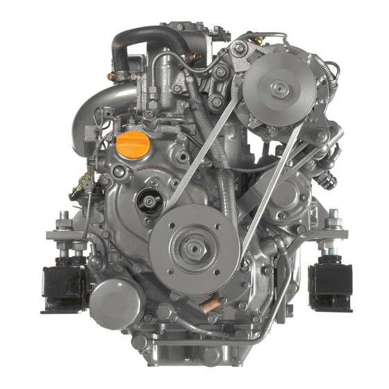
Any auxiliary equipment attached to the engine should be easy to The 1GM10 is a naturally aspirated use and accessible for service. To handle 1-cylinder engine equipped with a KM2P the drive equipment, propulsion systems marine gear. -
Page 16: New Engine Break-In
Low idle speed does not allow break-in of sliding A new Yanmar diesel engine must be parts. operated at suitable speeds and power settings during the break-in period to allow... -
Page 17: Component Identification
PRODUCT OVERVIEW 12/05 COMPONENT IDENTIFICATION Service Side - 1GM10 with KM2P Figure 1 and Figure 2 illustrate a typical version of a 1GM10 engine. Your engine may have different equipment from that illustrated. Figure 1 (16) (15) (14) (13) (12) -
Page 18: Non-Service Side - 1Gm10 With Km2P
PRODUCT OVERVIEW Non-Service Side - 1GM10 with KM2P Figure 2 (10) 0005849 Figure 2 1 – Decompression Lever 6 – Marine Gearbox 7 – Output Shaft Coupling 2 – Fuel Injection Valve 8 – Shift Lever 3 – Intake Silencer (Air Cleaner) 9 –... -
Page 19: Location Of Nameplates
PRODUCT OVERVIEW 12/05 LOCATION OF NAMEPLATES The nameplate of the Yanmar GM series The sail drive nameplate (Figure 5) is engine is shown in Figure 3. Check the attached to the sail drive. Check the sail engine’s model, output, engine speed and drive model and serial number. -
Page 20: Major Components And Functions
PRODUCT OVERVIEW MAJOR COMPONENTS AND FUNCTIONS Name of Component Function Decompression Lever Opens the exhaust valve and releases cylinder pressure to aid in manual engine starting Fuel Filter Removes dirt and water from the fuel. Drain the filter periodically. The filter element (filter) should be replaced periodically. -
Page 21: Control Equipment
PRODUCT OVERVIEW 12/05 CONTROL EQUIPMENT The control equipment at the helm makes remote control operation possible. It consists of the instrument panel, which is connected to the engine by a wire harness, and the throttle and shift console, which is connected by control cables to the engine control lever and marine gear. - Page 22 PRODUCT OVERVIEW Key Switch When the key is in the OFF position (Figure 7, (1)) the electric current is off. The key can be inserted or removed in this position. Figure 6 ( 1 ) ( 2 ) 0005847 Figure 7 1–OFF Position 2–ON Position The ON position (Figure 7, (2)) allows electrical current to the controls and equipment and...
- Page 23 PRODUCT OVERVIEW 12/05 B20-Type Figure 7Instrument Panel Options and Components 042563-00X01 Figure 8 1–“B20” instrument panel 2–Tachometer 3–Engine oil low pressure alarm lamp 4–Cooling water temperature alarm lamp 5–Seawater in sail drive alarm lamp (Optional) 6–Battery low charge alarm lamp 7–LCD (Hour meter) 8–Start switch 9–Power switch...
- Page 24 PRODUCT OVERVIEW Indicators and Alarms (Optional) When a sensor detects a problem during operation, the indicator on the instrument panel will light and an alarm will sound. Indicators are located on the instrument panel and the alarms are located on the back of the panel. Under normal operating conditions, the indicators are off.
- Page 25 Charge lamp Cooling water temperature lamp Engine lubricating oil pressure lamp LCD display Yanmar Full display Hourmeter When the warning devices are activated and normal operation is impossible, stop the engine and do not use it until the problem has been solved.
- Page 26 PRODUCT OVERVIEW Accessory power output The harness attached to the panel has a terminal where the signal that is synchronized to the panel power supply can be taken off. (Figure 9) (Refer to the See Wiring Diagrams on page 80.) The maximum current of this output terminal is 3A.
- Page 27 PRODUCT OVERVIEW 12/05 LCD control (hourmeter, coolant temperature, display brightness, oil pressure, battery voltage) Figure 9 You can switch (scroll) between displays by pressing the buttons on the bottom. Scroll Press the power switch. hourmeter. Pressing the right button on the bottom of Pressing the right button again shows the To set the brightness of the backlight: Press the left button continuously and...
-
Page 28: Single-Lever Throttle And Shift Console (Optional)
PRODUCT OVERVIEW Engine Stop Control Raising the decompression lever to the decompression position (Figure 11, (2)) The engine is stopped by pulling out the opens the exhaust valve and makes hand engine stop knob (Figure 10, (1)). This cranking of the engine possible. Returning cable is connected to the engine stop lever the lever to its RUN position (DOWN) and cuts off the fuel supply to the engine. - Page 29 The clutch is disengaged and the vessel is in NEUTRAL (no-load position). Note: Yanmar recommends the use of a single-lever type console for the remote control system. If only a two-lever type is available...
- Page 30 PRODUCT OVERVIEW This Page Intentionally Left Blank GM Series Operation Manual...
-
Page 31: Before You Operate
BEFORE YOU OPERATE INTRODUCTION SAFETY PRECAUTIONS This section of the Operation Manual Before performing any operations within describes the diesel fuel, engine oil and this section, review the Safety section on engine coolant specifications and how to page 3. replenish them. GM Series Operation Manual... -
Page 32: Diesel Fuel
• In the United States, biodiesel fuels must comply with the American Standard Only use diesel fuels recommended by ASTM D-6751 Grade-S15, D7467 Grade Yanmar for the best engine performance, B7-S15. to prevent engine damage. Only use clean diesel fuel. - Page 33 BEFORE YOU OPERATE 12/05 • Even biodiesel fuels that comply with a Handling of Diesel Fuel suitable standard as delivered will WARNING require additional care and attention to maintain the quality of the fuel in the Fire and Explosion Hazard. equipment or other fuel tanks.
- Page 34 BEFORE YOU OPERATE 2. Keep the fuel container stationary for Fuel System several hours to allow any dirt or water Install the fuel line from the fuel tank to the to settle to the bottom of the container. fuel injection pump as shown in Figure 3. Use a pump to extract the clear, filtered The recommended fuel / water separator fuel from the top of the container.
-
Page 35: Engine Oil
BEFORE YOU OPERATE 12/05 ENGINE OIL To fill the fuel tank: WARNING Engine Oil Specifications Fire and Explosion Hazard. Operate bilge ventilation (blowers) for a Only use the engine oil specified. Other minimum of 5 minutes to purge fumes engine oils may affect warranty coverage, from engine compartment after cause internal engine components to seize refueling. -
Page 36: Engine Oil Viscosity
See the SAE Service Grade Viscosity Chart (Figure 4). • Yanmar does not recommend the use of If you intend to operate your equipment at engine oil “additives.” temperatures outside the limits shown, you... -
Page 37: Adding Engine Oil
(Figure 5, (3)) on the dipstick (Figure 5, (2)). Never overfill the engine with engine oil. Engine Oil Capacity 1GM10 (V) (C) Full: 1.5 L (1.6 qt) 3. Insert the dipstick fully to check the level. Always keep the oil level between upper and lower lines on the oil cap / dipstick. -
Page 38: Checking Marine Gear Oil
BEFORE YOU OPERATE Checking Marine Gear Oil Adding Marine Gear Oil 1. Turn the engine off. Make sure the 1. Make sure the engine is as level as engine is as level as possible and wipe possible. area clean around the marine gear filler 2. -
Page 39: Cranking The Engine Manually
BEFORE YOU OPERATE 12/05 CRANKING THE ENGINE 5. Slide the starter handle (Figure 8, (1)) on the starter shaft (Figure 8, (1)), MANUALLY align the groove and pin, and turn the engine over about 10 times. Figure 6 When performing engine break-in or if the engine has not been used for a long period of time, engine oil will not be distributed to all the operating parts. -
Page 40: Cranking The Engine Electrically
BEFORE YOU OPERATE CRANKING THE ENGINE 5. With the key in the ON position, push the start button and the engine will ELECTRICALLY begin cranking. 6. Continue cranking for about 5 seconds and listen for any unusual noises. When performing engine break-in or if the engine has not been used for a long period of time, engine oil will not be distributed to If the engine stop knob is released... -
Page 41: Daily Checks
6. Check the electrical harnesses for cracks, abrasions, and damaged or Before starting for the day, make sure the corroded connectors. Yanmar engine is in good operating 7. Check hoses for cracks, abrasions, and condition. damaged, loose or corroded clamps. -
Page 42: Checking The Alternator Belt
BEFORE YOU OPERATE Checking the Alternator Belt Check the belt tension before use. See Checking and Adjusting the Alternator V-Belt Tension on page 56. Checking the Throttle and Shift Console Check the operation of the throttle and shift control lever. Make sure it moves smoothly. -
Page 43: Engine Operation
ENGINE OPERATION INTRODUCTION SAFETY PRECAUTIONS This section of the Operation Manual Before performing any operations within describes the diesel fuel, engine oil and this section, review the Safety section on engine coolant specifications and how to page 3. replenish them. It also describes the daily WARNING engine checkout. - Page 44 3 seconds premature engine wear and damage. after the ignition switch is turned on, • Contact your authorized Yanmar Marine consult authorized Yanmar Marine dealer engine dealer or distributor if the engine or distributor for service before operating...
-
Page 45: Starting The Engine Electrically
ENGINE OPERATION 12/05 STARTING THE ENGINE 4. Turn the master battery switch (if equipped) to ON. ELECTRICALLY 5. Turn the key switch to the ON position (Figure 2, (2)). Ensure that the instrument panel indicators light and the alarm sounds. This indicates that If the vessel is equipped with a water lift the indicators and the alarm are (water lock) muffler, excessive cranking... -
Page 46: Starting The Engine Manually
5. Raise the decompression lever up. See the key switch is in the ON position, Cranking the Engine Manually on consult authorized Yanmar Marine page 33. dealer or distributor for service before 6. Slide the starter handle (Figure 3, (2)) operating the engine. -
Page 47: Starting At Low Temperatures
Have your authorized 4. Pump fuel with the fuel feed pump by Yanmar Marine dealer or distributor moving the lever on the left side of the repair the damage. Avoid skin contact fuel feed pump up and down. -
Page 48: Throttle And Shift Lever Operation
Troubleshooting Chart on page 67 . clutch to NEUTRAL (Figure 4, (2)) and pause before slowly shifting to the If necessary, consult authorized Yanmar desired position. Do not shift abruptly Marine dealer or distributor. from FORWARD to REVERSE or vise versa. -
Page 49: Cautions During Operation
ENGINE OPERATION 12/05 CAUTIONS DURING Figure 4 OPERATION Engine trouble can arise if the engine is NEUTRAL operated for a long time under overloaded IPULLI CLUTCH conditions with the control handle in the full throttle position (maximum engine speed position), exceeding the continuous rated output engine speed. - Page 50 ENGINE OPERATION • Are there abnormal vibrations or noise? Racing the engine: With the gear in NEUTRAL, accelerate from the Excessive vibration may cause damage low-speed position to the high-speed to the engine, marine gear, hull and position and repeat this process about onboard equipment.
-
Page 51: Shutting Down The Engine
SHUTTING DOWN THE Figure 5 ENGINE Never stop the engine abruptly during operation. Yanmar recommends that when shutting the engine down, allow the engine 0005842 to run, without load, for 5 minutes. This will allow the engine components that operate... -
Page 52: Checking The Engine After Operation
ENGINE OPERATION CHECKING THE ENGINE AFTER OPERATION • Check that the key switch is in the OFF position and master battery switch (if equipped) is turned to OFF. • Fill the fuel tank. See Filling the Fuel Tank on page 28. •... -
Page 53: Periodic Maintenance
PERIODIC MAINTENANCE INTRODUCTION SAFETY PRECAUTIONS This section of the Operation Manual Before performing any maintenance describes the procedures for proper care procedures within this section, read the and maintenance of the engine. following safety information and review the Safety section on page 3. WARNING Crush Hazard If the engine needs to be... - Page 54 Any • When welding is completed, alterations to this engine may void its reconnect the alternator and engine warranty. Be sure to use Yanmar genuine control unit prior to reconnecting the replacement parts. batteries. Entanglement Hazard...
-
Page 55: Precautions
Yanmar Replacement Parts operating in an enclosed area. All internal combustion engines create Yanmar recommends that you use genuine carbon monoxide gas during operation. Yanmar parts when replacement parts are Accumulation of this gas within an needed. -
Page 56: Tightening Fasteners
When working on critical components that require calibrated tools, special procedures and specific tightening sequences, consult with your Yanmar distributor or dealer. The tightening torque in the Standard Torque Chart should be applied only to the bolts with a "7"... -
Page 57: Periodic Maintenance Schedule
Consult authorized Yanmar Marine dealer or distributor for assistance when checking items marked with a ●. GM Series Operation Manual... - Page 58 PERIODIC MAINTENANCE : Check or Clean ✧: Replace ●: Contact your authorized Yanmar Marine dealer or distributor Periodic Maintenance Interval Before Every Starting See Initial Every Every Every 1000 System Item Daily Hours or 4 Hours or Checks on...
-
Page 59: Periodic Maintenance Procedures
PERIODIC MAINTENANCE 12/05 PERIODIC MAINTENANCE Draining the Fuel Tank PROCEDURES WARNING When you are draining the fuel tank to After Initial 50 Hours of perform maintenance, put an approved Operation container under the opening to catch the fuel. Never use a shop rag to catch Perform the following maintenance after the fuel. - Page 60 PERIODIC MAINTENANCE Draining the Fuel Filter / Water Changing the Engine Oil Separator The engine oil in a new engine becomes contaminated from the initial break-in of WARNING internal parts. It is very important that the initial oil replacement is performed as When removing any fuel system scheduled.
- Page 61 PERIODIC MAINTENANCE 12/05 5. Approximately 10 minutes after Changing the Marine Gear Oil stopping the engine, remove the oil Note: Refer to the Operation Manual dipstick and check the oil level. Add oil supplied with your marine gear as necessary. or sail-drive unit for service and maintenance details.
- Page 62 Consult authorized WARNING Yanmar Marine dealer or distributor to adjust the intake / exhaust valve Perform this check with the key clearances. removed (the power switch off) and the...
-
Page 63: Every 50 Hours Of Operation
After the first 50 hours of operation, the alignment should be checked and readjusted if necessary. This is considered normal maintenance and the adjustment requires specialized knowledge and techniques. Consult your authorized Yanmar Marine dealer or distributor. GM Series Operation Manual... -
Page 64: Every 150 Hours Of Operation
PERIODIC MAINTENANCE 2. Turn the master battery switch to OFF Every 150 Hours of Operation (if equipped) or disconnect the negative (-) battery cable. Perform the following maintenance every 3. Remove the plugs and check the 150 hours of operation. electrolyte level in all cells. -
Page 65: Every 250 Hours Of Operation
If power is being used for onboard lights and other systems, the • Inspecting the Seawater Pump charging system may be inadequate. Impeller Consult your authorized Yanmar Marine • Inspecting the Zinc Anode dealer or distributor. • Cleaning the Intake Silencer (Air Filter) •... - Page 66 Wipe up any Bleeding from the Fuel System After spilled fuel immediately. Starting Failure on page 41. Dispose of waste properly. Inspecting the Fuel Injection Nozzle Spray Pattern Consult authorized Yanmar Marine dealer or distributor. GM Series Operation Manual...
- Page 67 If excessive amounts of performing this inspection. water leak continuously, the oil seal needs to be replaced. Consult authorized Yanmar 1. Loosen the cover bolts and remove the Marine dealer or distributor. pump side cover (Figure 5, (7)).
- Page 68 3. If the mixing elbow is damaged, repair The inspection intervals and replacement or replace it. Consult authorized schedule for the zinc anode are Yanmar Marine dealer or distributor. determined by seawater characteristics 4. Inspect the gasket and replace if and your operating environment. Inspect necessary.
-
Page 69: Every 1000 Hours Of Operation
PERIODIC MAINTENANCE 12/05 Checking the Wiring Connectors Every 1000 Hours of Operation Consult authorized Yanmar Marine dealer or distributor. Perform the following maintenance every 1000 hours or every 4 years of operation, Inspecting and Adjusting the whichever comes first. Intake / Exhaust Valve Clearances •... - Page 70 PERIODIC MAINTENANCE This Page Intentionally Left Blank GM Series Operation Manual...
-
Page 71: Troubleshooting
TROUBLESHOOTING SAFETY PRECAUTIONS TROUBLESHOOTING AFTER STARTING Before performing any troubleshooting procedures within this section, review the Just after the engine has started, check Safety section on page the following items at a low engine speed: If a problem occurs, stop the engine Is sufficient water being discharged immediately. -
Page 72: Troubleshooting Information
Check the engine room daily for any leaks refer to the Troubleshooting Chart on page or loose connections. 67 or consult authorized Yanmar Marine Is there sufficient fuel in the fuel tank? dealer or distributor. Refill fuel in advance to avoid running out Supply the authorized Yanmar Marine of fuel. -
Page 73: Troubleshooting Chart
Stop the engine and inspect. If no abnormality is identified and there is no problem alarm sounds during with operation, return to port at lowest speed and consult authorized Yanmar operation. Marine dealer or distributor. • Engine oil low pressure Engine oil level is low. - Page 74 Improper fuel Replace with recommended See Diesel Fuel fuel. Specifications on page 26. Problem with fuel injection Consult authorized Yanmar — Marine dealer or distributor. Compression leakage from Consult authorized Yanmar — intake / exhaust valve Marine dealer or distributor.
- Page 75 TROUBLESHOOTING 12/05 Symptom Probable Cause Measure Reference Abnormal Exhaust Color: Engine is overloaded. Consult authorized Yanmar — • Black smoke Marine dealer or distributor. Improper propeller Consult authorized Yanmar — matching Marine dealer or distributor. Dirty intake silencer (air Clean element.
- Page 76 TROUBLESHOOTING This Page Intentionally Left Blank GM Series Operation Manual...
-
Page 77: Long-Term Storage
6 months. If it remains unused for longer than this, please contact your authorized 1. Wipe off any dust or oil from the outside Yanmar Marine dealer or distributor. of engine. Before performing any storage procedures 2. Drain water from fuel filters. -
Page 78: Drain Seawater Cooling System
LONG-TERM STORAGE DRAIN SEAWATER RETURNING THE ENGINE COOLING SYSTEM TO SERVICE In cold temperatures or before long-term 1. Replace the oil and the oil filter before storage, be sure to drain the seawater running the engine. from the cooling system. 2. -
Page 79: Specifications
SPECIFICATIONS PRINCIPAL ENGINE SPECIFICATIONS GM Series Operation Manual... -
Page 80: 1Gm10 Engine
SPECIFICATIONS 1GM10 Engine Type Vertical 4-cycle water-cooled diesel engine Combustion System Swirl pre-combustion chamber Number of Cylinders Bore and Stroke 75 mm x 72 mm (2.95 in. x 2.83 in.) Displacement 0.318 L (19.4 cu. in.) Continuous Rating Output at Crankshaft / 5.9 kW (8 hp metric) / 3400 min... -
Page 81: 1Gm10C Engine
SPECIFICATIONS 12/05 1GM10C Engine Type Vertical 4-cycle water-cooled diesel engine Combustion System Swirl pre-combustion chamber Number of Cylinders Bore and Stroke 75 mm x 72 mm (2.95 in. x 2.83 in.) Displacement 0.318 L (19.4 cu. in.) Continuous Rating Output at Crankshaft / 5.9 kW (8 hp metric) / 3400 min Output Engine Speed... -
Page 82: 1Gm10V Engine
SPECIFICATIONS 1GM10V Engine Type Vertical 4-cycle water-cooled diesel engine Combustion System Swirl pre-combustion chamber Number of Cylinders Bore and Stroke 75 mm x 72 mm (2.95 in. x 2.83 in.) Displacement 0.318 L (19.4 cu. in.) Continuous Output at Crankshaft / 5.9 kW (8 hp metric) / 3400 min Rating Output Engine Speed... -
Page 83: System Diagrams
GM Series Operation Manual SYSTEM DIAGRAMS PIPING DIAGRAMS Notation Screw Joint (Union) Spherical Pipe Joint Drilled Hole Cooling Seawater Piping Lubricating Oil Piping Fuel Oil Piping Steel Pipe Rubber Hose Vinyl Pipe GM Series Operation Manual... - Page 84 SYSTEM DIAGRAMS 1GM10 Piping Diagram Figure 1 GM Series Operation Manual...
- Page 85 SYSTEM DIAGRAMS 12/05 1 – Engine oil pressure adjusting Notation valve Fuel Pump 2 – Oil pressure switch 3 – Fuel injection nozzle Engine Oil Pipe 4 – Fuel return pipe 5 – To main bearing Cooling Water Pipe 6 – To main bearing Drilled Hole 7 –...
-
Page 86: Wiring Diagrams
SYSTEM DIAGRAMS WIRING DIAGRAMS Figure 11GM10 Series A-Type Instrument Panel Figure 2 GM Series Operation Manual... - Page 87 SYSTEM DIAGRAMS 12/05 1 – Instrument panel (A Type) 2 – Alarm lamps (3 to 6) Color Coding Engine Harness 3 – Battery low charge indicator 4 – Cooling water high temperature indicator Black 5 – Engine oil low pressure White Ignition indicator...
- Page 88 SYSTEM DIAGRAMS Figure 21GM10 Series B20-Type Instrument Panel Figure 3 GM Series Operation Manual...
- Page 89 SYSTEM DIAGRAMS 12/05 1 – Instrument panel B20 (Option) 2 – Alarm lamps (3 to 6) Color Coding Engine Harness 3 – Engine oil low pressure indicator 4 – Cooling water high Black temperature indicator White Ignition 5 – Water in sail drive seal Blue Air Heater / Glow (option) indicator...
- Page 90 SYSTEM DIAGRAMS This Page Intentionally Left Blank GM Series Operation Manual...
- Page 91 Yanmar Co., Ltd. Street: Town: Tsuruno-cho, Kitaku, Osaka-City 530-8311 Japan Post Code: Country: Name of Authorised Representative: Yanmar Co., Ltd. Marine Operations Division 5-3-1 Tsukaguchi Honmachi, Amagasaki, Hyogo Street: Town: 661-0001 Japan Post Code: Country: Société Nationale de Certification et d'Homologation...
- Page 93 OPERATION MANUAL 1GM10, 1GM10C, 1GM10V 1st edition: November 2007 2nd edition: March 2012 2nd edition 1st rev.: September 2012 2nd edition 2nd rev.: June 2013 Issued by: YANMAR CO., LTD. Marine Operations Division Edited by: YANMAR TECHNICAL SERVICE CO., LTD.
- Page 94 0AGMM-G00101...