Yanmar 1GM10 Operation Manual
Gm series marine engines
Hide thumbs
Also See for 1GM10:
- Service manual (464 pages) ,
- Shop manual (241 pages) ,
- Operation manual (94 pages)
Table of Contents
Advertisement
Quick Links
Advertisement
Table of Contents
Troubleshooting

Related Manuals for Yanmar 1GM10


Summary of Contents for Yanmar 1GM10
- Page 1 OPERATION MANUAL 1GM10 1GM10C 1GM10V P/N: 0AGMM-G00100 MARINE ENGINES...
- Page 2 / or exemplify a product, service or maintenance improvement. We reserve the right to make any change at any time without notice. Yanmar and registered trademarks of Yanmar Co., Ltd. in Japan, the United States and / or other countries.
-
Page 3: Table Of Contents
........Product Overview ............9 Yanmar GM Features and Applications ....... New Engine Break-In ........Component Identification ........Service Side - 1GM10 with KM2P ...... Non-Service Side - 1GM10 with KM2P ....Location of Nameplates .......... Emission-Control Labels ........Major Components and Functions ...... - Page 4 The Importance of Periodic Maintenance ..... Performing Periodic Maintenance ...... The Importance of Daily Checks ......Keep a Log of Engine Hours and Daily Checks ..Yanmar Replacement Parts ......Tools Required ..........GM Series Operation Manual © 2007 Yanmar Marine International...
- Page 5 TABLE OF CONTENTS Ask Your Authorized Yanmar Marine Dealer or Distributor For Help ........Tightening Fasteners ........EPA Maintenance Requirements ......EPA Requirements for USA and Other Applicable Countries ............. Conditions to Ensure Compliance with EPA Emission Standards ........Inspection and Maintenance ......
- Page 6 TABLE OF CONTENTS This Page Intentionally Left Blank GM Series Operation Manual © 2007 Yanmar Marine International...
-
Page 7: Introduction
This manual should be considered a permanent part of the To help you enjoy your Yanmar GM series engine and remain with it. engine for many years to come, please follow these recommendations: •... -
Page 8: Record Of Ownership
INTRODUCTION RECORD OF OWNERSHIP Take a few moments to record the information you need when you contact Yanmar for service, parts or literature. Engine Model: Engine Serial No.: Date Purchased: Dealer: Dealer Phone: GM Series Operation Manual © 2007 Yanmar Marine International... -
Page 9: Safety
SAFETY Yanmar considers safety of great DANGER importance and recommends that anyone Indicates a hazardous situation which, if who comes in close contact with its not avoided, will result in death or products, such as those who install, serious injury. -
Page 10: Safety Precautions
• Safety signs and decals are additional reminders for safe operating and maintenance techniques. • See your authorized Yanmar Marine dealer or distributor for additional training. GM Series Operation Manual © 2007 Yanmar Marine International... - Page 11 NEVER operate the engine while wearing a headset to listen to music or radio because it will be difficult to hear the warning signals. Stop the engine before you begin to service GM Series Operation Manual © 2007 Yanmar Marine International...
- Page 12 NEVER check for a fuel leak with your loosening or tightening engine parts. hands. ALWAYS use a piece of wood or cardboard. Have your authorized Yanmar Flying Object Hazard Marine dealer or distributor repair the damage.
- Page 13 If a Yanmar Marine Engine is installed at an overloading the engine that is running. angle that exceeds the specifications stated...
-
Page 14: Location Of Safety Decals
SAFETY LOCATION OF SAFETY DECALS Figure 1 shows the location of safety decals on Yanmar GM series marine engines. GM Engines ( 1 ) WARNING 128296-07350 0005961 Figure 1 1 – Part Number: 128296–07350 GM Series Operation Manual © 2007 Yanmar Marine International... -
Page 15: Product Overview
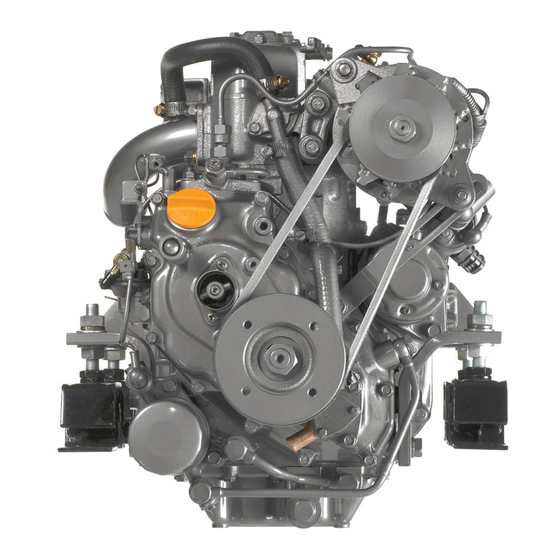
(including the propeller) and other onboard equipment, always observe the instructions The 1GM10 is a naturally aspirated and cautions given in the operation manuals 1-cylinder engine equipped with a KM2P supplied by the shipyard and original marine gear. -
Page 16: New Engine Break-In
• With the clutch in NEUTRAL, accelerate from the low speed position to the high A new Yanmar diesel engine must be speed position briefly. operated at suitable speeds and power • Repeat this process five times. -
Page 17: Component Identification
PRODUCT OVERVIEW COMPONENT IDENTIFICATION Service Side - 1GM10 with KM2P Figure 1 and Figure 2 illustrate a typical version of a 1GM10 engine. Your engine may have different equipment from that illustrated. (16) (15) (14) (13) (12) (11) (10) 0005850 Figure 1 1 –... -
Page 18: Non-Service Side - 1Gm10 With Km2P
PRODUCT OVERVIEW Non-Service Side - 1GM10 with KM2P (10) 0005849 Figure 2 1 – Decompression Lever 6 – Marine Gearbox 2 – Fuel Injection Valve 7 – Output Shaft Coupling 3 – Intake Silencer (Air Cleaner) 8 – Shift Lever 4 –... -
Page 19: Location Of Nameplates
To ensure safe operation, emission-control labels have been attached to the engine. Their location is shown in Figure 6. They The nameplate of the Yanmar GM series should always be visible. Replace labels if engine is shown in Figure 3. Check the damaged or lost. -
Page 20: Major Components And Functions
The starter motor cranks the engine and is powered by the battery. Alternator The alternator is belt driven and generates electricity to charge the battery. Engine Oil Dipstick Gauge stick for checking the engine oil level GM Series Operation Manual © 2007 Yanmar Marine International... -
Page 21: Control Equipment
6 – Key Switch 7 – Warning Buzzer 8 – Start Button 9 – Option “B” Instrument Panel 10 – Engine Tachometer 11 – Instrument Panel Light Switch 12 – Hour Meter GM Series Operation Manual © 2007 Yanmar Marine International... - Page 22 To stop the engine, keep the key normal engine operation can resume. switch in the ON position and pull the engine stop knob. After stopping the engine, turn the key to the OFF position. GM Series Operation Manual © 2007 Yanmar Marine International...
- Page 23 Stop operation immediately to avoid damage to the engine. Check the oil level and troubleshoot the lubrication system. GM Series Operation Manual © 2007 Yanmar Marine International...
-
Page 24: Optional Single-Lever Throttle And Shift Console
The clutch is disengaged CLUTCH and the vessel is in NEUTRAL (no-load position). Note: Yanmar recommends the use of a single-lever type console for the remote 0005846 control system. If only a two-lever type is Figure 15 available in the market, reduce engine 1 –... -
Page 25: Before You Operate
Diesel Fuel Specifications daily engine checks. NOTICE: Only use diesel fuels Before performing any operations within this recommended by Yanmar for the best section, review the Safety section on engine performance, to prevent engine page 3. damage and to comply with EPA warranty requirements. - Page 26 • PAH (polycyclic aromatic hydrocarbons) and ignite fuel vapors. content should be below 10% by volume. • Do not use Biocide. • Do not use kerosene or residual fuels. GM Series Operation Manual © 2007 Yanmar Marine International...
-
Page 27: Fuel System
20 to 30 mm (0.75 to 1.125 in.) above the 10 – Fuel Tank bottom of the tank (Figure 2, (4)) so that only clean fuel is distributed to the engine. GM Series Operation Manual © 2007 Yanmar Marine International... -
Page 28: Filling The Fuel Tank
Stop fueling when the gauge shows the fuel tank is full. CAUTION! NEVER overfill the fuel tank. Replace the fuel cap and hand-tighten. Over-tightening the fuel cap will damage it. GM Series Operation Manual © 2007 Yanmar Marine International... -
Page 29: Engine Oil
150 hours thereafter. See limits shown, you must consult your Changing the Engine Oil on page authorized Yanmar Marine dealer or distributor for special lubricants or starting aids. Select the oil viscosity based on the ambient temperature where the engine is being operated. -
Page 30: Checking The Engine Oil
(Figure 5, (3)) and lower (Figure 5, (4)) lines on the dipstick. Add oil if necessary. See Adding Engine Oil on page 24. Fully reinsert the dipstick. GM Series Operation Manual © 2007 Yanmar Marine International... -
Page 31: Marine Gear Or Sail-Drive Oil
Remove the dipstick. The oil level should be between the upper (Figure 6, (2)) and lower (Figure 6, (3)) lines on the dipstick. Fully reinsert the dipstick. QuickSilver is a registered trademark of Brunswick Corporation. GM Series Operation Manual © 2007 Yanmar Marine International... -
Page 32: Adding Marine Gear Oil
Put the remote control shift lever in the NEUTRAL position. Raise the decompression lever (Figure 7, (3)) up. 0005838 Figure 7 1 – RUN Position 2 – Decompression Position 3 – Decompression Lever GM Series Operation Manual © 2007 Yanmar Marine International... -
Page 33: Cranking The Engine Electrically
With the key in the ON position, push RUN position. the start button and the engine will begin cranking. Continue cranking for about 5 seconds and listen for any unusual noises. GM Series Operation Manual © 2007 Yanmar Marine International... -
Page 34: Recheck The Engine Oil
Before starting for the day, make sure the start. NEVER start the engine in this Yanmar engine is in good operating mode. condition. CAUTION! It is important to perform daily checks as listed in this Recheck the Engine Oil Operation Manual. -
Page 35: Checking Diesel Fuel And Engine Oil
(for at least one refill) onboard, to be ready for emergencies. Check the battery electrolyte level before use. See Inspecting the Battery Electrolyte Level (Serviceable Batteries Only) on page GM Series Operation Manual © 2007 Yanmar Marine International... - Page 36 BEFORE YOU OPERATE This Page Intentionally Left Blank GM Series Operation Manual © 2007 Yanmar Marine International...
-
Page 37: Engine Operation
All internal combustion engines create carbon monoxide gas during operation and special precautions are required to avoid carbon monoxide poisoning. GM Series Operation Manual © 2007 Yanmar Marine International... -
Page 38: Starting The Engine Electrically
• If the ambient temperature is below -16˚C (+5˚F), rubber components such as gaskets and seals will harden causing premature engine wear and damage. • Contact your authorized Yanmar Marine engine dealer or distributor if the engine will be operated outside of this standard temperature range. -
Page 39: Starting The Engine Manually
Yanmar Marine dealer or distributor for service 0005888 before operating the engine. Figure 3 1 – Starting Shaft 2 – Starting Handle Turn the master battery switch (if equipped) to ON. GM Series Operation Manual © 2007 Yanmar Marine International... -
Page 40: Restarting After Starting Failure
Pump fuel with the fuel feed pump by you are exposed to high-pressure moving the lever on the left side of the fuel spray, obtain prompt medical fuel feed pump up and down. treatment. GM Series Operation Manual © 2007 Yanmar Marine International... - Page 41 59 or Troubleshooting Chart on page bottom clogged? • Is the seawater suction hose broken or does the hose suck air because of If necessary, see your authorized Yanmar a loose clamp? Marine dealer or distributor. GM Series Operation Manual...
-
Page 42: Throttle And Shift Lever Operation
0005846 Figure 4 1 – FORWARD (FWD) 2 – NEUTRAL (N) 3 – REVERSE (REV) 4 – Pull the lever to disengage the clutch. GM Series Operation Manual © 2007 Yanmar Marine International... -
Page 43: Precautions During Operation
High- pressure fuel can penetrate your skin and result in serious injury. If you are exposed to high-pressure fuel spray, obtain prompt medical treatment. GM Series Operation Manual © 2007 Yanmar Marine International... -
Page 44: Shutting Down The Engine
This can lead to abnormal completely stopped, it may restart. combustion when the engine is restarted and is not desirable. GM Series Operation Manual © 2007 Yanmar Marine International... -
Page 45: Checking The Engine After Operation
• If there is a risk of freezing, drain the seawater system. See Draining the Cooling System on page 66. • At temperatures below 0˚C (32˚F), drain seawater system and connect the engine heater (if equipped). GM Series Operation Manual © 2007 Yanmar Marine International... - Page 46 ENGINE OPERATION This Page Intentionally Left Blank GM Series Operation Manual © 2007 Yanmar Marine International...
-
Page 47: Periodic Maintenance
ALWAYS use the engine lifting eyes when lifting the engine. Additional equipment is necessary to lift the marine engine and marine gear together. ALWAYS use lifting equipment with sufficient capacity to lift the marine engine. GM Series Operation Manual © 2007 Yanmar Marine International... - Page 48 Be sure to possible to the welding point. use Yanmar genuine replacement parts. • NEVER connect the weld clamp to the engine or in a manner which would allow current to pass through a mounting bracket.
-
Page 49: Precautions
Yanmar Replacement Parts Performing Periodic Maintenance Yanmar recommends that you use genuine Yanmar parts when replacement parts are WARNING! NEVER block windows, needed. Genuine replacement parts help vents or other means of ventilation if the ensure long engine life. -
Page 50: Tightening Fasteners
Apply 80% working on critical components that require torque when tightened to aluminum calibrated tools, special procedures and alloy. specific tightening sequences, consult with your Yanmar distributor or dealer. Bolt diameter x pitch M6x1.0 M8x1.25 M10x1.5 M12x1.75 M14x1.5... -
Page 51: Epa Maintenance Requirements
Compliance with EPA Emission keep the emission values of your engine in Standards the standard values during the warranty The 1GM10, 1GM10C and 1GM10V are period. The warranty period is determined EPA-certified engines. by the age of the engine or the number of hours of operation. -
Page 52: Periodic Maintenance Schedule
See your authorized Yanmar Marine dealer or distributor for assistance when checking items marked with a ●. GM Series Operation Manual... - Page 53 PERIODIC MAINTENANCE ◯: Check or Clean ◊: Replace ●: Contact your authorized Yanmar Marine dealer or distributor Periodic Maintenance Interval Before Every Every Starting Every Every System Item Initial 50 1000 See Daily Hours Hours Hours or Checks on Hours...
-
Page 54: Inspection And Maintenance Of Epa Emission-Related Parts
Check fuel injection nozzle pressure and spray pattern 3000 hours Check fuel injection pump adjustment 3000 hours Note: The inspection and maintenance items shown above should be performed at your Yanmar Marine dealer or distributor. GM Series Operation Manual © 2007 Yanmar Marine International... -
Page 55: Periodic Maintenance Procedures
Close the fuel cock. Put a pan under the fuel / water separator. Remove the fuel filter cover and drain any water and dirt collected inside. Reassemble the fuel filter. GM Series Operation Manual © 2007 Yanmar Marine International... -
Page 56: Changing The Engine Oil
Fill the marine gear with clean marine dipstick and check the oil level. Add oil gear oil. See Marine Gear Oil as necessary. Specifications on page 25. Perform a trial run and check for oil leaks. GM Series Operation Manual © 2007 Yanmar Marine International... - Page 57 Improper adjustment will cause the engine to run noisily, resulting in poor engine performance and engine damage. See your authorized Yanmar Marine dealer or distributor to adjust the intake / exhaust valve clearances. GM Series Operation Manual...
-
Page 58: Every 50 Hours Of Operation
See Draining the Fuel Filter / Water requires specialized knowledge and Separator on page 49. techniques. Consult your authorized Yanmar Marine dealer or distributor. GM Series Operation Manual © 2007 Yanmar Marine International... -
Page 59: Every 150 Hours Of Operation
(-) battery cable. (3/8 to 9/16 in.) above the plates. Remove the plugs and check the electrolyte level in all cells. NOTICE: NEVER attempt to remove the covers or fill a maintenance-free battery. GM Series Operation Manual © 2007 Yanmar Marine International... -
Page 60: Every 250 Hours Of Operation
• Draining the Fuel Tank systems, the charging system may be • Replacing the Fuel Filter Element inadequate. Consult your authorized Yanmar Marine dealer or distributor. • Inspecting the Fuel Injection Nozzle Spray Pattern • Replacing the Engine Oil Filter Element •... - Page 61 Place an approved container under the Inspecting the Fuel Injection Nozzle fuel filter. Spray Pattern Loosen the retaining ring See your authorized Yanmar Marine dealer (Figure 4, (2)) counterclockwise with a or distributor. filter wrench. Note: When removing the fuel...
- Page 62 (Figure 5, (7)). during operation. If excessive amounts of water leak continuously, the oil seal needs to be replaced. See your authorized Yanmar Marine dealer or distributor. NOTICE: During normal operation, the pump impeller rotates in a counterclockwise direction (Figure 6, (1)).
- Page 63 Cleaning the Breather Pipe The zinc anode is located on the inside of the anode plug and is labeled “Anticorrosion See your authorized Yanmar Marine dealer Zinc.” or distributor. Cleaning the Intake Silencer (Air Checking and Adjusting the...
-
Page 64: Every 1000 Hours Of Operation
Alternator V-Belt Tension • Tightening All Major Nuts and Bolts • Adjusting the Propeller Shaft Alignment Inspecting the Fuel Injection Timing See your authorized Yanmar Marine dealer or distributor. Inspecting the Seawater Pump Impeller See Inspecting the Seawater Pump Impeller on page 55. -
Page 65: Troubleshooting
Periodically operate the engine near maximum speed while under way. This will generate higher exhaust temperatures, which will help clean out hard carbon deposits, maintain engine performance and prolong the life of the engine. GM Series Operation Manual © 2007 Yanmar Marine International... -
Page 66: Troubleshooting Information
Troubleshooting Chart on page 61 vibrations. Avoid operation in this speed or see your authorized Yanmar Marine range. If any abnormal sounds are heard, dealer or distributor. stop the engine and inspect for the cause. -
Page 67: Troubleshooting Chart
Stop the engine and inspect. If no abnormality is identified and there is no problem alarm sounds during with operation, return to port at lowest speed and see your authorized Yanmar operation. Marine dealer or distributor. • Engine oil low Engine oil level is low. - Page 68 Power lacking because See your authorized accessory drive is engaged Yanmar Marine dealer or — distributor. Engine cannot be turned Internal parts seized See your authorized manually. Yanmar Marine dealer or — distributor. GM Series Operation Manual © 2007 Yanmar Marine International...
- Page 69 Yanmar Marine dealer or — distributor. Fuel injection timing off See your authorized Yanmar Marine dealer or — distributor. Engine burning oil (excessive See your authorized consumption) Yanmar Marine dealer or — distributor. GM Series Operation Manual © 2007 Yanmar Marine International...
- Page 70 TROUBLESHOOTING This Page Intentionally Left Blank GM Series Operation Manual © 2007 Yanmar Marine International...
-
Page 71: Long-Term Storage
If it remains unused for longer maintenance interval, perform those than this, please contact your authorized maintenance procedures before putting the Yanmar Marine dealer or distributor. engine into long-term storage. Wipe off any dust or oil from the outside of the engine. -
Page 72: Draining The Cooling System
0005887 Figure 1 1 – Cam 2 – Inlet 3 – Outlet 4 – Seawater Pump Body 5 – Impeller 6 – Gasket 7 – Side Cover Close the drain cock. GM Series Operation Manual © 2007 Yanmar Marine International... -
Page 73: Specifications
Lubrication System Complete enclosed forced lubrication system Rating Condition: Temperature of fuel: 25˚C at fuel pump inlet; ISO 3046-1 Rating Condition: Temperature of fuel: 40˚C at fuel pump inlet; ISO 8665 GM Series Operation Manual © 2007 Yanmar Marine International... - Page 74 Engine Weight with Marine Gear 76 kg (167 lb) Note: Density of fuel: 0.842g/cm at 15˚C. Fuel temperature at the inlet of the fuel injection pump. 1 hp metric = 0.7355 kW GM Series Operation Manual © 2007 Yanmar Marine International...
-
Page 75: 1Gm10C Engine Specifications
1290 rpm Propeller Speed Reverse 1290 rpm Rating Condition: Temperature of fuel: 25˚C at fuel pump inlet; ISO 3046-1 Rating Condition: Temperature of fuel: 40˚C at fuel pump inlet; ISO 8665 GM Series Operation Manual © 2007 Yanmar Marine International... - Page 76 Engine Weight with Sail-Drive 104 kg (229 lb) Note: Density of fuel: 0.842g/cm at 15˚C. Fuel temperature at the inlet of the fuel injection pump. 1 hp metric = 0.7355 kW GM Series Operation Manual © 2007 Yanmar Marine International...
-
Page 77: 1Gm10V Engine Specifications
12 VDC, 1.0 kW (12 VDC, 1.4 hp metric) System AC Generator 12V, 35A Rating Condition: Temperature of fuel: 25˚C at fuel pump inlet; ISO 3046-1 Rating Condition: Temperature of fuel: 40˚C at fuel pump inlet; ISO 8665 GM Series Operation Manual © 2007 Yanmar Marine International... - Page 78 Engine Weight with Marine Gear 90 kg (198 lb) Note: Density of fuel: 0.842g/cm at 15˚C. Fuel temperature at the inlet of the fuel injection pump. 1 hp metric = 0.7355 kW GM Series Operation Manual © 2007 Yanmar Marine International...
-
Page 79: System Diagrams
SYSTEM DIAGRAMS PIPING DIAGRAMS Notation Screw Joint (Union) Spherical Pipe Joint Drilled Hole Cooling Seawater Piping Lubricating Oil Piping Fuel Oil Piping Steel Pipe Rubber Hose Vinyl Pipe GM Series Operation Manual © 2007 Yanmar Marine International... - Page 80 SYSTEM DIAGRAMS 1GM10 Piping Diagram Figure 1 GM Series Operation Manual © 2007 Yanmar Marine International...
- Page 81 Fuel Inlet Fuel Feed Pump Fuel Filter Exhaust Gas Cooling Water Thermostat Seawater Inlet Seawater Pump Fuel Filter Engine Oil Filter (Inlet Side) Engine Oil Pump Engine Oil Filter (Outlet Side) GM Series Operation Manual © 2007 Yanmar Marine International...
-
Page 82: Wiring Diagrams
SYSTEM DIAGRAMS WIRING DIAGRAMS 1GM10 Series A-Type Instrument Panel Figure 2 GM Series Operation Manual © 2007 Yanmar Marine International... - Page 83 Cooling Water Temperature Lamp (Cross sectional area) Charge Lamp Push Button Switch Key Switch Light Switch Not Used (Except 1GM10) Fuse Extension Cable 3 m (Standard). The total length extension cable must be less than 6 m. GM Series Operation Manual...
- Page 84 SYSTEM DIAGRAMS 1GM10 Series B-Type Instrument Panel Figure 3 GM Series Operation Manual © 2007 Yanmar Marine International...
- Page 85 (Cross sectional area) A + B + C < 5 m → 40 mm Cooling Water Temperature Lamp (Cross sectional area) Charge Lamp Push Button Switch Key Switch Not Used (Except 1GM10) Fuse GM Series Operation Manual © 2007 Yanmar Marine International...
- Page 86 SYSTEM DIAGRAMS This Page Intentionally Left Blank GM Series Operation Manual © 2007 Yanmar Marine International...
-
Page 87: Emission System Warranty
Yanmar. (CARB), the Environmental Protection Agency (EPA) and Yanmar Co., Ltd. The warranty period is hereafter referred to as Yanmar, are pleased Engines rated at or five (5) years or 3,000 to explain the emission control system above 19 kW ≤ and hours of use, less than <... -
Page 88: Warranty Coverage
Repair or replacement of of the engine as delivered by Yanmar to the any warranted part will be performed at an original retail purchaser. Such components... -
Page 89: Customer Assistance
You are responsible for initiating the warranty process. You must present your engine to a Yanmar dealer as soon as a problem exists. The warranty repairs should be completed by the dealer as expeditiously as possible. -
Page 90: Gm Series Operation Manual
Maintenance Log Date Operating Maintenance Performed Dealer Name Stamp or Hours Signature GM Series Operation Manual © 2007 Yanmar Marine International... - Page 91 Date Operating Maintenance Performed Dealer Name Stamp or Hours Signature GM Series Operation Manual © 2007 Yanmar Marine International...
- Page 92 GM Series Operation Manual © 2007 Yanmar Marine International...