Motorola MC67 User Manual
With android os
Hide thumbs
Also See for MC67:
- User manual (224 pages) ,
- Integrator manual (164 pages) ,
- Quick start manual (2 pages)
Table of Contents
Advertisement
Quick Links
Download this manual
See also:
User Manual
Advertisement
Table of Contents
Troubleshooting

Related Manuals for Motorola MC67


Summary of Contents for Motorola MC67
- Page 1 MC67 WITH ANDROID™ OS USER GUIDE January 2014 MN000115A01 © 2014 Motorola Solutions, Inc. All rights reserved...
-
Page 3: Copyrights
United States and other countries preserve for Motorola certain exclusive rights for copyrighted computer programs. Accordingly, any copyrighted Motorola computer programs contained in the Motorola products described in this document may not be copied or reproduced in any manner without the express written permission of Motorola. ©... -
Page 5: Revision History
Revision History Changes to the original guide are listed below: Change Date Description Rev. A 01/2014 Initial release. MN000115A01 | January 2014 | Send Feedback... -
Page 7: Table Of Contents
Display Setting..............................33 Setting the Screen Brightness........................33 Setting Screen Rotation........................... 34 Setting Screen Timeout Setting.......................34 Setting Font Size............................. 35 General Sound Setting............................35 Chapter 2: Using the MC67.................. 37 Home Screen............................... 37 Status Bar..............................38 Status Icons..........................38 Notification Icons........................40 Managing Notifications...........................41 Application Shortcuts and Widgets......................41... - Page 8 8 | Contents Removing an App or Widget from the Home Screen..............42 Folders..............................42 Creating a Folder......................... 42 Naming Folders........................... 42 Removing a Folder........................43 Home Screen Wallpaper..........................43 Changing the Home Screen Wallpaper..................43 Stylus and Touchscreen...........................43 Using the On-screen Keyboard........................... 44 Keypads................................
- Page 9 Contents | 9 Working with Albums..........................74 Share an Album........................... 75 Get Album Information....................... 75 Deleting an Album........................75 Working with Photos..........................75 Viewing and Browsing Photos....................75 Rotating a Photo.......................... 76 Cropping a Photo.........................76 Setting a Photo as a Contact Icon....................77 Get Photo Information.........................77 Share a Photo..........................78 Deleting a Photo..........................
- Page 10 Unpairing a Bluetooth Device.......................102 Data Usage................................ 102 Chapter 7: Accessories..................105 Accessories................................105 Single Slot USB Cradle.............................106 Charging the MC67 Battery........................107 Charging a Spare Battery........................107 Battery Charging........................... 108 Four Slot Charge Only Cradle...........................108 Charging the MC67..........................108 Battery Charging........................... 108 Four Slot Ethernet Cradle..........................109...
- Page 11 Contents | 11 Four Slot Battery Charger........................129 Cables..............................129 Magnetic Stripe Reader......................... 130 Chapter 9: Technical Specifications..............131 MC67.................................131 Chapter 10: Keypads................... 135 Numeric Keypad Configuration........................135 Alpha-numeric Keypad Configurations......................137 DSD Keypad Configuration..........................140...
- Page 12 12 | Contents...
-
Page 13: List Of Tables
Table 21: Troubleshooting the Magnetic Stripe Reader ...............130 Table 22: MC67 Technical Specifications ..................131 Table 23: Data Capture Supported Symbologies ................133 Table 24: MC67 Numeric Keypad Descriptions ................135 Table 25: Numeric Keypad Input States ..................137 Table 26: Alpha-numeric Keypad Descriptions ................138 Table 27: QWERTY Keypad Input States ..................139... - Page 14 14 | List of Tables...
-
Page 15: List Of Figures
List of Figures | 15 List of Figures Figure 1: Manufacturing Label ....................... 21 Figure 2: MC67 Front View ......................24 Figure 3: MC67 Rear View ......................25 Figure 4: Lift SIM Slot Holder Door ....................26 Figure 5: Insert microSD Card in Holder ..................26 Figure 6: Lifting the SIM Cover ..................... - Page 16 16 | List of Figures Figure 33: Dialer Screen ......................... 56 Figure 34: Call in Progress ......................56 Figure 35: Dialer Contacts Tab .......................57 Figure 36: Call History Tab ......................58 Figure 37: Two Calls ........................59 Figure 38: Merged Calls ......................... 59 Figure 39: Un-merge Calls ......................
- Page 17 Figure 79: Removing the MC67 ....................114 Figure 80: Cable Cup Locking Tabs .....................116 Figure 81: Windshield Installation ....................117 Figure 82: Insert MC67 into Vehicle Holder ................118 Figure 83: Mounting Disk ......................118 Figure 84: Vehicle Holder Mounted on Flat Surface ..............119 Figure 85: Removing the Screen Protector ...................122...
- Page 18 18 | List of Figures...
-
Page 19: About This Guide
Note: Screens and windows pictured in this guide are samples and can differ from actual screens. Documentation Set The documentation set for the MC67 provides information for specific user needs, and includes: • MC67 Quick Start Guide - describes how to get the MC67 up and running. -
Page 20: Chapter Descriptions
Topics covered in this guide are as follows: • Getting Started on page 23 provides information on getting the MC67 up and running for the first time. • Using the MC67 on page 37 provides information for operating the MC67. -
Page 21: Related Documents
Motorola Solutions responds to calls by email or telephone within the time limits set forth in support agreements. If the problem cannot be solved by Motorola Solutions Global Customer Support, the user may need to return the equipment for servicing and will be given specific directions. Motorola Solutions is not responsible for any damages incurred during shipment if the approved shipping container is not used. -
Page 23: Chapter 1: Getting Started
3 Inspect the equipment for damage. If any equipment is missing or damaged, contact the Motorola Solutions Global Customer Support center immediately. 4 Prior to using the MC67 for the first time, remove the protective shipping film that covers the scan window, display and camera window. -
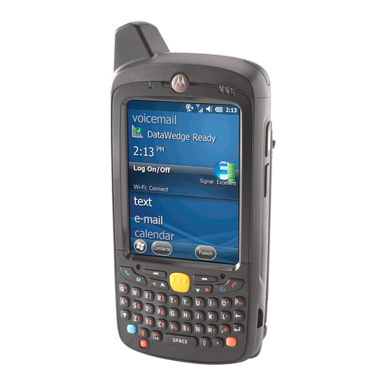
Page 24: Features
Figure 2: MC67 Front View Table 1: Front View Features Number Item Function Touch Screen Displays all information needed to operate the MC67. Data Capture LED Indicates data capture status. Charging/Battery Indicates battery charging status. Status LED WAN Radio Status Indicate WAN radio status. -
Page 25: Setup
Securely holds the battery in place. Setup When and where to use: Perform this procedure to start using the MC67 for the first time. Procedure: 1 Install a micro secure digital (SD) card (optional, required for saving photos, videos and sound recordings). -
Page 26: Installing A Microsd Card
26 | Getting Started 5 Power on the MC67. Installing a microSD Card The microSD card slot provides secondary non-volatile storage. The slot is located under the battery pack. Refer to the documentation provided with the card for more information, and follow the manufacturer’s recommendations for use. -
Page 27: Installing The Sim Card
Installing the Battery Procedure: 1 Insert the battery, bottom first, into the battery compartment in the back of the MC67. 2 Press the battery down into the battery compartment until the battery release latch snaps (two clicks) into place. Note: If the battery has significant charge, the MC67 turns on. -
Page 28: Charging The Battery
Before using the MC67 for the first time, charge the main battery until the amber Charging/Battery Status light emitting diode (LED) remains lit. To charge the MC67, use a cable or a cradle with the appropriate power supply. For information about the accessories available for the MC67, see Accessories on page 105 for more information. -
Page 29: Replacing The Battery
Replacing the Battery Procedure: 1 If the MC67 is in a cradle, remove it before performing a Safe Battery Swap. 2 Unclip the handstrap. 3 Press and hold the Power button until the menu appears. Figure 9: Power Button Menu 4 Touch Battery swap. -
Page 30: Replacing The Microsd Card
30 | Getting Started Figure 11: Lift the Battery 8 Insert the replacement battery, bottom first, into the battery compartment in the back of the MC67. 9 Press the battery down until the battery release latch snaps (two clicks) into place. -
Page 31: Replacing The Sim Card
SeePerforming a Soft Reset on page Battery Management Note: Prior to checking the battery charge level, remove the MC67 from any AC power source (cradle or cable). To check the charge status of the main battery, on the Home screen touch >... -
Page 32: Low Battery Notification
Some applications include buttons that open screens with settings to adjust power use. Low Battery Notification When the battery charge level drops below 20%, the MC67 displays a notice to connect the MC67 to power. The user should charge the battery using one of the charging accessories. -
Page 33: Turning Off The Radios
Setting the Date and Time The date and time is automatically synchronized using an NITZ server when the MC67 is connected to a cellular network. The user is only required to set the time zone or set the date and time when not connected to a cellular network. -
Page 34: Setting Screen Rotation
Figure 15: Brightness Dialog Box 5 In the Brightness dialog box, check the Automatic brightness checkbox to set the MC67 to automatically adjust the brightness using the built-in light sensor. Uncheck the checkbox to set the brightness manually. Use the slider to set a brightness level. -
Page 35: Setting Font Size
Getting Started | 35 Setting Font Size To set the size of the font is system applications: Procedure: 1 Touch 2 Touch 3 Touch Display. 4 Touch Font size. 5 Select one of the font size values. • Small • Normal (default) •... -
Page 36: Figure 17: Volumes Dialog Box
36 | Getting Started Figure 17: Volumes Dialog Box • Call Ringtone and Vibrate • Phone ringtone - touch to select a ringtone to sound when an incoming call is received. • Vibrate when ringing - Check to make the device vibrate when a call is received. •... -
Page 37: Chapter 2: Using The Mc67
Chapter Using the MC67 Introduction This chapter explains the buttons, status icons, and controls on the MC67, and provides basic instructions for using the MC67, including resetting the MC67 and entering data. Home Screen The Home screen displays when the MC67 turns on. Depending upon the configuration, the Home screen might appear different. -
Page 38: Status Bar
1 — Status Bar Displays the time, status icons (right side), and notification icons (left side). For more information see and . 2 — Shortcut Icons Opens applications installed on the MC67. See Application Shortcuts and Widgets on page 41 for more information. - Page 39 Using the MC67 | 39 Icon Description Indicates that the TC55 is searching location data. Indicates that the Alarm is active. Indicates that all sounds except media and alarms are silenced and vibrate mode is active. Indicates that the ringer is silenced.
-
Page 40: Notification Icons
40 | Using the MC67 Icon Description Connected to an GPRS network. Roaming from a network. No SIM card installed. Notification Icons Table 7: Notification Icons Icon Description Indicates that more notifications are available for viewing. Indicates that data is syncing. -
Page 41: Managing Notifications
Using the MC67 | 41 Icon Description Indicates a missed call. Indicates that USB tethering is active. Managing Notifications Notification icons report the arrival of new messages, calendar events, and alarms, as well as ongoing events. When a notification occurs, an icon appears in the Status bar with a brief description. See... -
Page 42: Moving Items On The Home Screen
42 | Using the MC67 4 Touch and hold the icon or widget until the Home screen appears. 5 Position the icon on the screen and then release. Moving Items on the Home Screen Procedure: 1 Touch and hold the item until it floats on the screen. -
Page 43: Removing A Folder
4 Touch Save or Set wallpaper. Stylus and Touchscreen Use the MC67 stylus to select items and enter information. The stylus functions as a mouse. • Touch: Touch the screen once with the stylus to press option buttons and open menu items. -
Page 44: Using The On-Screen Keyboard
• Keys with alternate characters display an ellipsis ( ... ) below the character. Keypads The MC67 offers three keypad configurations: Numeric, alphanumeric QWERTY and Direct Store Delivery (DSD). Figure 23: MC67 Numeric Keypad Keypads on page 135 for detailed information on the keypad configurations. -
Page 45: Applications
Using the MC67 | 45 Applications The APPS screen displays icons for all installed applications. The table below lists the applications installed on the MC67. Refer to the MC67 Integrator Guide for information on installing and uninstalling application. Table 8: Applications Icon Description Browser - Use to access the Internet or intranet. - Page 46 MLog Manager - Use to capture log files for diagnostics. See MLog Manager on page 81 more information. MSP Agent - Enables management of the MC67 from an MSP server. Requires the purchase of an appropriate MSP client license per device to suit the level of management functionality required.
-
Page 47: Accessing Applications
Using the MC67 | 47 Icon Description AppLock Administrator - Use to configure the Application Lock feature. This icon appears after the optional application is installed. MultiUser Administrator - Use to configure the MultiUser feature. This icon appears after the optional application is installed. -
Page 48: Un-Locking The Screen
Un-Locking the Screen Use the Lock screen to protect access to data on the MC67. Some email account require locking the screen. Refer to the MC67 Integrator Guide for information on setting up the locking feature. The Locking feature functions differently in Single User mode or Multiple User mode. -
Page 49: Figure 26: Lock Screen
Using the MC67 | 49 Figure 26: Lock Screen Figure 27: PIN Screen MN000115A01 | January 2014 | Send Feedback... -
Page 50: Multiuser Mode
50 | Using the MC67 Figure 28: Pattern Screen Figure 29: Password Screen MultiUser Mode With MultiUser login, multiple users can log on to the device with each user having access to various applications and features. When enabled, the Login screen appears after powering on, resetting or after the device wakes from suspend mode. -
Page 51: Multiuser Logout
3 The device reboots. Performing a Hard Reset Caution: Performing a hard reset with a SIM card installed in the MC67 may cause damage or data corruption to the SIM card. Perform a hard reset if the MC67 stops responding. -
Page 52: Suspend Mode
3 The MC67 shuts down and then reboots. Suspend Mode The MC67 goes into suspend mode when the user presses the Power button or after a period of inactivity (set in the Display settings window). To wake the MC67 from Suspend mode, press the Power button. -
Page 53: Led Indicators
Using the MC67 | 53 LED Indicators The MC67 has three light emitting diode (LED) indicators. The Data Capture LED indicates status for scanning. The Charging/Battery Status LED indicates battery charging and status. The Radio Status LED indicates Wide Area Network (WAN) radio status. -
Page 55: Chapter 3: Calls
Chapter Calls Make a phone call from the Phone application, the People application or other applications or widgets that display contact information. Emergency Calling The service provider programs one or more emergency phone numbers, such as 911 or 999, that the user can call under any circumstances, even when the phone is locked, a SIM card is not inserted or the phone is not activated. -
Page 56: Figure 33: Dialer Screen
56 | Calls Figure 33: Dialer Screen Touch the tab above the dialer. 3 Touch the keys to enter the phone number. Touch below the dialer to initiate the call. Figure 34: Call in Progress If… Then… You want to display the dialer. Touch You want to turn on the speakerphone. -
Page 57: Making A Call Using Contacts
Calls | 57 If… Then… You want to mute the call. Touch You want to place the call on hold. Touch You want to add another person to the call. Touch Touch to end the call. Making a Call Using Contacts Procedure: On the Home screen touch 2 Touch the... -
Page 58: Making A Conference Call
58 | Calls • - Outgoing call. Procedure: On the Home screen touch Touch the tab. Figure 36: Call History Tab Touch next to the contact to initiate the call. Touch to end the call. Making a Conference Call To create a conference phone session with multiple people. Note: Conference Calling and the number of conference calls allowed may not be available on all services. -
Page 59: Figure 37: Two Calls
Calls | 59 8 When the call connects, the first call is placed on hold and the second call is active. Figure 37: Two Calls Touch icon to create a conference call with three people. Figure 38: Merged Calls Touch to add another call. -
Page 60: Making A Call Using A Bluetooth Headset
60 | Calls Figure 39: Un-merge Calls To remove a caller from the conference, touch next to the caller. Note: To speak privately with one party during a conference call, touch Manage Conference and then touch the caller. To include all parties again, touch Making a Call Using a Bluetooth Headset Procedure: 1 Pair the Bluetooth headset with the device. -
Page 61: Figure 40: Incoming Call Screen
Calls | 61 Figure 40: Incoming Call Screen All incoming calls are recorded in the Phone application Call log tab. If you miss a call, you receive a notification. To silence the ringer before answering the call, press the volume down button on the side of device. When a call arrives, touch the white phone icon and slide over one of these icons: Figure 41: Select Answer Options •... -
Page 62: Answering Calls With A Bluetooth Headset
62 | Calls Answering Calls with a Bluetooth Headset When you receive a phone call, the Incoming Call screen opens, displaying the caller ID and any additional information about the caller that is in the People application. Figure 42: Incoming Call Screen All incoming calls are recorded in the Phone application Call log tab. - Page 63 Calls | 63 Note: Call Forwarding may not be available on all networks. Check with the service provider for availability. • Always forward - set to forward all calls to a different phone number. • Forward when busy - enter the phone number to forward calls only when the line is busy. •...
-
Page 65: Chapter 4: Applications
Chapter Applications This section describes the applications installed on the device. File Browser Use the File Browser application to view and mange files on the device. To open File Browser, touch > Figure 43: File Browser Screen The address bar (1) indicates the current folder path. Touch the current folder path to manually enter a path and folder name. -
Page 66: Messaging
66 | Applications Touch and hold an item to perform an operation on that item. Select one of the options from the File Operations menu: • Information - View detailed information about the file or folder. • Move - Move the file or folder to a new location. •... -
Page 67: People
Applications | 67 People Use the People application to manage contacts. From a Home or Apps screen, touch . People opens to the main list of contacts. View contacts in three ways at the top of the screen: Groups , All contacts , and Favorites. Touch the tabs to change how to view the contacts. Swipe up or down to scroll through the lists. -
Page 68: Calling A Person By Name
68 | Applications Figure 45: Voice Dialer Window The user says one of the following commands: • Call • Dial • Redial • Open. Calling a Person By Name Procedure: 1 Launch Voice Dialer. 2 Say “Call John Doe.” 3 In the Voice Dialer dialog box, touch Call John Doe The call is initiated. -
Page 69: Camera
The application opens. Camera This section provides information for taking photos and recording videos using the integrated digital cameras. Note: A microSD card has to be installed in the MC67 to save photos and videos. Figure 46: No Storage Warning Taking Photos... -
Page 70: Taking A Panoramic Photo
70 | Applications Touch to adjust exposure, flash, and other settings using the camera settings. See Camera Settings on page for more information. Touch and to adjust the zoom level. 6 Frame the subject on screen. Touch The camera brings the image into focus. When the image is in focus, the focus indicators in each corner turn green, the camera takes a photo and a shutter sound plays. -
Page 71: Recording Videos
Applications | 71 If panning too quickly, the message Too fast appears. Touch to end the shot. The panorama appears immediately and a progress indicator displays while it saves the image. 7 Touch the thumbnail to view the photo in Gallery. See Gallery on page Recording Videos To record a video:... -
Page 72: Video Settings
72 | Applications Touch to display the camera setting options. • Settings - Touch to open a scrolling list of settings: • Store location - Include location information with each photo using the device global positioning system (GPS). Options: On or Off (default). •... -
Page 73: Gallery
Applications | 73 • HD 720p - High definition 720p. • SD 480p - Standard definition 480p. • Time lapse interval - Touch to select a time interval to set the frame rate for time lapse photography. Options: Off (default), 1s, 1.5s, 2s, 2.5s, 3s, 5s or 10s. •... -
Page 74: Working With Albums
74 | Applications Figure 50: Gallery — Albums • Touch an album to open it and view its contents. The photos and videos in the album are displayed in chronological order. • Touch a photo or video in an album to view it. •... -
Page 75: Share An Album
Applications | 75 Share an Album Procedure: 1 Touch Touch 3 Touch and hold an album until it highlights. 4 Touch other albums as required. Touch . The Share menu opens. Touch the application to use to share the selected albums. 6 Follow the instructions within the selected application. -
Page 76: Rotating A Photo
76 | Applications Figure 52: Photo Example 5 Swipe left or right to view the next or previous photo in the album. 6 Turn the device to view the photo in upright (portrait) or sideways (landscape) orientation. The photo is displayed (but not saved) in the new orientation. -
Page 77: Setting A Photo As A Contact Icon
Applications | 77 Figure 53: Cropping Tool 5 Touch OK to save a copy of the cropped photo. The original version is retained. Setting a Photo as a Contact Icon Procedure: 1 Touch Touch 3 Touch an album to open it. 4 Touch the photo to open it. -
Page 78: Share A Photo
78 | Applications Share a Photo Procedure: 1 Touch Touch 3 Touch an album to open it. 4 Touch a photo to open it. Touch 6 Touch the application to use to share the selected photo. The application selected opens with the photo attached to a new message. -
Page 79: Sharing A Video
Applications | 79 Figure 54: Video Example Touch . The video begins to play. 6 Touch the screen to view the playback controls. Sharing a Video Procedure: 1 Touch Touch 3 Touch an album to open it. 4 Touch a video to open it. Touch . -
Page 80: Datawedge Demonstration
Opens a menu to view the application information or to set the application DataWedge profile. Note: See the MC67 Integrator Guide for information on DataWedge configuration. Either press a Scan key or touch the yellow scan button in the application to enable data capture. The captured data appears in the text field below the yellow button. -
Page 81: Mlog Manager
Applications | 81 Figure 56: Sound Recorder Application MLog Manager Use MLog Manager to capture log files for diagnostics. See the MC67 Integrator Guide for detailed information on configuring the application. Figure 57: MLog Manager MN000115A01 | January 2014 |... -
Page 83: Chapter 5: Data Capture
• Decode Mode: In this mode, the MC67 attempts to locate and decode enabled bar codes within its field of view. The imager remains in this mode as long as the user holds the scan button, or until it decodes a bar code. -
Page 84: Scanning Considerations
Procedure: 1 Ensure that an application is open on the MC67 and a text field is in focus (text cursor in text field). 2 Point the exit window on the top of the MC67 at a bar code. -
Page 85: Digital Camera Scanning
Procedure: 1 Ensure that an application is open on the MC67 and a text field is in focus (text cursor in text field). 2 Point the camera lens on the back of the MC67 at a bar code. -
Page 86: Datawedge
3 Press and hold a scan button. A preview window appears on the display window. Note: When Picklist mode is enabled, move the MC67 until the bar code is centered under the red target on the screen. Move the MC67 until the bar code is visible on the screen. - Page 87 Data Capture | 87 4 Touch Settings. 5 Touch the DataWedge enabled checkbox. The blue checkmark disappears from the checkbox indicating that DataWedge is disabled. 6 Touch MN000115A01 | January 2014 | Send Feedback...
-
Page 89: Chapter 6: Wireless
The tethering settings allow you to share your data connection. You can share the MC67’s mobile data connection with a single computer via USB tethering or Bluetooth tethering. While the MC67 is sharing its data connection, an icon appears at the top of the screen and a corresponding message appears in the notification list. -
Page 90: Bluetooth Tethering
90 | Wireless 6 Check USB tethering. The host computer is now sharing the device’s data connection. Post requisites: To stop sharing the data connection, uncheck USB tethering or disconnect the USB cable. Bluetooth Tethering Use Bluetooth tethering to share the data connection with a host computer. Prerequisites: Configure the host computer to obtain its network connection using Bluetooth. -
Page 91: Locking The Sim Card
Wireless | 91 6 Touch 2G only. 7 Touch Locking the SIM Card Locking the SIM card requires the user to enter a PIN every time the device is turned on. If the correct PIN is not entered, only Emergency calls can be made. Procedure: 1 Touch Touch... -
Page 92: Wireless Local Area Networks
Wireless local area networks (WLANs) allow the MC67 to communicate wirelessly inside a building. Before using the MC67 on a WLAN, the facility must be set up with the required hardware to run the WLAN (sometimes known as infrastructure). The infrastructure and the MC67 must both be properly configured to enable this communication. -
Page 93: Figure 63: Settings Screen
Connect. See the system administrator for more information. The MC67 obtains a network address and other required information from the network using the dynamic host configuration protocol (DHCP) protocol. To configure the MC67 with a fixed internet protocol (IP) address, See Configuring the Device to Use a Static IP Address on page 7 In the Wi-Fi setting field, Connected appears indicating that the MC67 is connected to the WLAN. -
Page 94: Configuring A Wi-Fi Network
94 | Wireless Configuring a Wi-Fi Network To set up a Wi-Fi network: Procedure: 1 Touch Touch 3 Touch Wi-Fi. 4 Slide the switch to the ON position. 5 The device searches for WLANs in the area and lists them on the screen. 6 Scroll through the list and select the desired WLAN network. -
Page 95: Manually Adding A Wi-Fi Network
Wireless | 95 Manually Adding a Wi-Fi Network Manually add a Wi-Fi network if the network does not broadcast its name (SSID) or to add a Wi-Fi network when out of range. Procedure: 1 Touch Touch 3 Touch Wi-Fi. 4 Slide the Wi-Fi switch to the On position. 5 Touch + at the bottom of the screen. -
Page 96: Configuring The Device To Use A Static Ip Address
96 | Wireless 3 Touch Proxy settings and select Manual. Figure 66: Proxy Settings 4 In the Proxy hostname text box, enter the address of the proxy server. 5 In the Proxy port text box, enter the port number for the proxy server. Note: When entering proxy addresses the Bypass proxy for field, do not use spaces or carriage returns between addresses. -
Page 97: Advanced Wi-Fi Settings
Wireless | 97 5 If required, in the Gateway text box, enter a gateway address for the device. 6 If required, in the Network prefix length text box, enter a the prefix length. 7 If required, in the DNS 1 text box, enter a Domain Name System (DNS) address. 8 If required, in the DNS 2 text box, enter a DNS address. -
Page 98: Bluetooth
When AFH is enabled, the Bluetooth radio “hops around” (instead of through) the 802.11b high-rate channels. AFH coexistence allows Motorola Enterprise Tablets to operate in any infrastructure. The Bluetooth radio in this device operates as a Class 2 device power class. The maximum output power is 2.5 mW and the expected range is 10 meters (32.8 ft.). -
Page 99: Bluetooth Profiles
• Object Push Profile (OPP) - Allows the MC67 to push and pull objects to and from a push server. • Advanced Audio Distribution Profile (A2DP) - Allows the MC67 to stream stereo-quality audio to a wireless headset or wireless stereo speakers. -
Page 100: Enabling Bluetooth
4 Touch Discovering Bluetooth Device(s) The MC67 can receive information from discovered devices without pairing. However, once paired, the MC67 and a paired device exchange information automatically when the Bluetooth radio is on. To find Bluetooth devices in the area: Procedure: 1 Ensure that Bluetooth is enabled on both devices. -
Page 101: Changing The Bluetooth Name
11 The Bluetooth device is added to the Bluetooth devices list and a trusted (“paired”) connection is established. Changing the Bluetooth Name By default, the MC67 has a generic Bluetooth name that is visible to other devices when connected. Procedure:... -
Page 102: Unpairing A Bluetooth Device
102 | Wireless 5 Under PROFILES, check or uncheck a profile to allow the device to use that profile. 6 Touch Unpairing a Bluetooth Device To unpair a Bluetooth device and erase all pairing information: Procedure: 1 Touch 2 Touch 3 Touch Bluetooth. - Page 103 Wireless | 103 Mobile Data Usage Caution: The usage displayed on the data usage settings screen is measured by your device. Your carrier's data usage accounting may differ. Usage in excess of your carrier plan's data limits can result in steep overage charges.
-
Page 105: Chapter 7: Accessories
MC67 with an Ethernet network. CRD5501-4000ER provides up to a maximum of 1 Gbps. Vehicle Cradle VCD5500-1001R Installs in a vehicle and charges the MC67 main battery. Vehicle Holder VCH5500-1000R Provides an alternative mounting solution for the MC67 in a vehicle. Requires the Auto Charge cable for charging the MC67 battery. -
Page 106: Single Slot Usb Cradle
KT-137521-03R Package of 3 screen protectors. Single Slot USB Cradle This section describes how to use a Single Slot USB cradle with the MC67. For USB communication setup procedures refer to the MC67 Integrator Guide. Send Feedback | January 2014 | MN000115A01... -
Page 107: Charging The Mc67 Battery
• Provides 5.4 VDC power for operating the MC67. • Synchronizes information between the MC67 and a host computer. Refer to the MC67 Integrator Guide for information on setting up a partnership between the MC67 and a host computer. •... -
Page 108: Battery Charging
Charge batteries in temperatures from 0°C to 40°C (32°F to 104°F). Charging is intelligently controlled by the MC67. To accomplish this, for small periods of time, the MC67 or cradle alternately enables and disables battery charging to keep the battery at acceptable temperatures. The MC67 or cradle indicates when charging is disabled due to abnormal temperatures via its LED. -
Page 109: Four Slot Ethernet Cradle
Accessories | 109 To accomplish this, for small periods of time, the MC67 alternately enables and disables battery charging to keep the battery at acceptable temperatures. The MC67 indicates when charging is disabled due to abnormal temperatures via its LED. -
Page 110: Establishing Ethernet Connection
100 Mbps On/Blink 10 Mbps Four Slot Battery Charger This section describes how to use the Four Slot Battery Charger to charge up to four MC67 batteries. Charging Spare Batteries Procedure: 1 Connect the charger to a power source. 2 Insert the battery into a battery charging well and gently press down on the battery to ensure proper contact. -
Page 111: Battery Charging
Magnetic Stripe Reader The MSR snaps on to the bottom of the MC67 and removes easily when not in use. When attached to the MC67, the MSR allows the MC67 to capture data from magnetic stripe cards. With the MSR attach, the MC67 can still be charged by placing the MC67 with MSR into a cradle or connecting to a charging cable. -
Page 112: Removing The Msr
2 Secure by snapping the arms into the MC67 housing. Removing the MSR Procedure: 1 To remove the MSR open the arms. Pull the MSR from the MC67. Note: When attaching a cable with a cup connector through the MSR to charge the device, you cannot swipe cards. -
Page 113: Vcd5000 Vehicle Cradle
2 Press the MC67 down to ensure it is seated properly. A click indicates that the MC67 button release locking mechanism is enabled and the MC67 is locked in place. Caution: Ensure the MC67 is fully inserted in the cradle. Lack of proper insertion may result in property damage or personal injury. -
Page 114: Removing The Mc67
Charge batteries in temperatures from 0°C to 40°C (32°F to 104°F). Charging is intelligently controlled by the MC67. To accomplish this, for small periods of time, the MC67 alternately enables and disables battery charging to keep the battery at acceptable temperatures. The MC67 indicates when charging is disabled due to abnormal temperatures via its LED. -
Page 115: Battery Charging And Operating Power
1 To charge the MC67 battery, connect the communication/charge cable power input connector to the Motorola approved power source. 2 Slide the bottom of the MC67 into the connector cup end of the communication/charge cable and gently press in until it latches into the MC67. -
Page 116: Led Charge Indications
Figure 80: Cable Cup Locking Tabs The MC67 amber Charge LED indicates the MC67 battery charging status. 4 When charging is complete, push the two locking tab down and remove the cable from the MC67. LED Charge Indications The amber Charge LED on the MC67 indicates battery charging status. See... -
Page 117: Vehicle Holder
2 Flip the lever down to create a vacuum between the suction cup and the mounting surface. 3 Make sure that the suction bond is strong enough before proceeding to the next step. 4 Slide the MC67 into the cradle. MN000115A01 | January 2014 |... -
Page 118: Flat Surface Installation
Figure 82: Insert MC67 into Vehicle Holder Locking Tab 5 Connect the auto charger cable to the MC67 and slide the two locking tabs up to secure the cable cup to the MC67. 6 Connect the other end to the cigarette lighter socket. -
Page 119: Figure 84: Vehicle Holder Mounted On Flat Surface
Accessories | 119 Figure 84: Vehicle Holder Mounted on Flat Surface 7 Connect the auto charger cable to the MC67 and slide the two locking tabs up to secure the cable cup to the MC67. 8 Connect the other end to the cigarette lighter socket. -
Page 121: Chapter 8: Maintenance And Troubleshooting
The touch-sensitive screen of the MC67 is glass. Do not to drop the MC67 or subject it to strong impact. • Protect the MC67 from temperature extremes. Do not leave it on the dashboard of a car on a hot day, and keep it away from heat sources. -
Page 122: Battery Safety Guidelines
In the event of a battery leak, do not allow the liquid to come in contact with the skin or eyes. If contact has been made, wash the affected area with large amounts of water and seek medical advice. • If you suspect damage to your equipment or battery, contact Motorola Solutions Global Customer Support Center to arrange for inspection. Send Feedback... -
Page 123: Cleaning Instructions
Read warning label on compressed air and alcohol product before using. If you have to use any other solution for medical reasons please contact Motorola for more information. Warning: Avoid exposing this product to contact with hot oil or other flammable liquids. If such exposure occurs, unplug the device and clean the product immediately in accordance with these guidelines. -
Page 124: Cleaning The Mc67
Table 14: Troubleshooting the MC67 Problem Cause Solution When pressing the Battery not charged. Charge or replace the battery in the MC67. power button the Battery not installed Install the battery properly. See Installing the Battery on page MC67 does not turn properly. - Page 125 LEDs blink. charged. Battery did not charge. Battery failed. Replace battery. If the MC67 still does not operate, perform a reset. See Resetting the Device on page MC67 removed from Insert MC67 in cradle. The 3600 mAh battery fully charges in cradle while battery was less than six hours.
- Page 126 Refer to the EMDK or DataWedge application. MC67 is not programmed If the MC67 does not beep on a good decode, set the to generate a beep. application to generate a beep on good decode.
-
Page 127: Single Slot Usb Cradle
AC power. battery is inserted. MC67 is not seated firmly Remove and re-insert the MC67 into the cradle, ensuring it is in the cradle. firmly seated. Spare battery is not seated Remove and re-insert the spare battery into the charging slot, firmly in the cradle. -
Page 128: Four Slot Charge Only Cradle
Battery is not charging. MC67 removed from the Replace the MC67 in the cradle. The 3600 mAh battery fully cradle too soon. charges in less than six hours. Battery is faulty. Verify that other batteries charge properly. If so, replace the faulty battery. -
Page 129: Four Slot Battery Charger
Battery is faulty. Verify that other batteries charge properly. If so, replace the faulty battery. The MC67 is not fully Detach and re-attach the power cable to the MC67, ensuring it attached to power. is firmly connected. During data Cable was disconnected Re-attach the cable and retransmit. -
Page 130: Magnetic Stripe Reader
Battery is faulty. Verify that other batteries charge properly. If so, replace the faulty battery. The MC67 is not fully Detach and re-attach the MSR to the MC67, ensuring it is attached to the MSR. firmly connected. During data MC67 detached from Reattach MC67 to MSR and retransmit. -
Page 131: Chapter 9: Technical Specifications
Chapter Technical Specifications The following sections provide technical specification for the device. MC67 Table 22: MC67 Technical Specifications Item Description Physical Characteristics Dimensions Height: 16.2 cm (6.38 in.) Width: 7.7 cm (3.03 in.) Depth: 3.35 cm (1.32 in.) Weight 385 g (13.5 oz.) Display Color 3.5”... - Page 132 4 g’s PK Sine (5 Hz to 2 kHz); 0.04g2/Hz Random (20 Hz to 2 kHz); 60 minute duration per axis, 3 axis Thermal Shock -40° C to 70° C (-40° F to 158° F) rapid transition Motorola Interactive Sensor Technology (IST) Motion Sensor 3-axis accelerometer provides motion-sensing for dynamic screen orientation and power management...
-
Page 133: Table 23: Data Capture Supported Symbologies
Technical Specifications | 133 Item Description ™ Voice Communications Voice-over-IP ready, Wi-Fi -certified, IEEE 802.11a/b/g/n direct ™ sequence wireless LAN, Wi-Fi Multimedia (WMM and WMM-PS) Wireless PAN Data and Voice Communications Bluetooth Class II, v2.1 with Enhanced Data Rate (EDR) Global Positioning System Integrated stand-alone or Assisted-GPS (A-GPS) Data Capture Specifications... - Page 134 134 | Technical Specifications Item Description 2D Bar Codes Australian Postal, Composite AB, Dutch Postal, Maxi Code, PDF-417, UK Postal, Aztec, Composite C, Japanese Postal, Micro PDF-417, QR Code, US Postnet, Canadian Postal, Data Matrix, Linked Aztec, microQR, US Planet, USPS 4-state (US4CB), Send Feedback | January 2014 | MN000115A01...
-
Page 135: Chapter 10: Keypads
The numeric keypad contains application keys, scroll keys, and function keys. The keypad is color-coded to indicate the alternate function key (blue) values. Note that an application can change keypad functions so the MC67’s keypad may not function exactly as described. See the tables below for key and button descriptions and for the keypad’s special functions. - Page 136 136 | Keypads Description Press the Orange key, then the Shift key to add a shift (that applies only to the next key pressed) to the orange lock state. Press and release the SHIFT key to activate the keypad alternate SHIFT state. Press SHIFT the Orange key and then the Shift key to produce uppercase characters.
-
Page 137: Alpha-Numeric Keypad Configurations
Keypads | 137 Description key and then press the ‘7’ key once to produce the letter ‘S’; press and release the Orange key, press and release the SHIFT key and then press the ‘7’ key three times to produce the letter ‘S’. Deletes the previous character. -
Page 138: Table 26: Alpha-Numeric Keypad Descriptions
138 | Keypads Figure 87: QWERTY Keypad Configuration Table 26: Alpha-numeric Keypad Descriptions Description Green Key Press to display the Phone application. After entering a phone number, press to initiate the call. Press to answer an incoming call. Press to stop dialing or end a call. Red Key Orange Key Accesses the secondary layer of characters and actions (shown on the keypad in... -
Page 139: Table 27: Qwerty Keypad Input States
Keypads | 139 Description Moves right one item. Scroll Right Moves up one item. Scroll Up Moves down one item. Scroll Down Changes the state of the alpha characters from lowercase to uppercase. Press the Shift Shift key to activate this state temporarily, followed by another key. Displays the previous screen. -
Page 140: Dsd Keypad Configuration
(blue) values. Note that an application can change keypad functions so the MC67’s keypad may not function exactly as described. See the tables below for key and button descriptions and for the keypad’s special functions. -
Page 141: Table 28: Mc67 Dsd Keypad Descriptions
Keypads | 141 Figure 88: DSD Keypad Descriptions Table 28: MC67 DSD Keypad Descriptions Description Blue Key Use the Blue key to access items shown on the keypad in blue. Press the Blue key once followed by another key. A single press illuminates the key until the second key is pressed. - Page 142 142 | Keypads Description Moves right one item. Scroll Right Moves up one item. Scroll Up Moves down one item. Scroll Down Produces a space character. SPACE In default state, produces the numeric value on the key. In Alpha state, produces the Alphanumeric lower case alphabetic characters on the key.
-
Page 143: Table 29: Dsd Keypad Input States
Keypads | 143 Table 29: DSD Keypad Input States Numeric State Orange Key (Alpha Lowercase State) Blue+ Key 1st Press 2nd Press 3rd Press 4th Press Note: An application can change the key functions. The keypad may not function exactly as described. MN000115A01 | January 2014 | Send Feedback... - Page 145 Index | 145 Index datawedge 45, DEX cable adaptive frequency hopping diagnostics adjust volume display airplane mode cleaning albums downloads alphanumeric keypad drop specification application shortcuts DSD keypad applock administrator DWDemo approved cleanser audio modes auto charge cable email emergency calling backup battery Ethernet connection battery 25,...
- Page 146 Ethernet cradle MC67 operating system 19, single slot USB cradle vehicle cradle TTLS TTLS-MSCHAP panoramic TTLS-MSCHAPv2 PEAP-GTC TTLS-PAP...