
Related Manuals for Orion VCB-X


Summary of Contents for Orion VCB-X
- Page 1 VCB-X Controller Field Technical Guide VCB-X Controller Code: SS1051 Version 2.0 and up Requires Modular Service Tool SD Code: SS1063 Version 1.0 and up Requires System Manager TS II Code: SS7002 Version 2.0 and up...
-
Page 2: Table Of Contents
EM2 Expansion Module Dimensions ........................16 12 Relay Expansion Module Dimensions ......................17 VCB-X Controller Components ..........................18 INSTALLATION & WIRING ......................19 VCB-X Input and Output Wiring ..........................20 E-BUS Digital Room Sensor ..........................22 E-BUS CO Wall Mounted Sensor ........................23 Duct Mounted E-BUS CO Sensor ........................ - Page 3 Heat Pump Adaptive Defrost Operation ......................... 71 Water Source Heat Pump Operation ........................72 Water Source Heat Pump Safety Monitoring ......................73 Head Pressure Control ............................74 Temperature Protection ............................74 Outdoor Air Lockouts ............................. 74 System Broadcasts ..............................74 VCB-X Controller Field Technical Guide...
- Page 4 Relay Outputs ................................ 77 Trend Logging ................................ 77 TROUBLESHOOTING ........................78 LED Diagnostics ..............................78 VCB-X Controller & VCB-X EM1 Expansion Module LED Locations ..............79 LED Operation ............................... 80 APPENDIX A ..........................81 System Confi gurations ............................81 Space, Outdoor Air, or Return Air Temperature Sensor Testing ................85 Copeland Discharge Thermistor Temperature Sensor Testing ................
-
Page 5: Overview
5 confi gurable relay outputs. The VCB-X EM2 Expansion Module (OE336-23-EM2-A) provides an additional 1 analog • Remote SAT Reset Signal input, 2 analog outputs, and 3 binary inputs. The VCB-X 12 • Return Air Bypass Control Relay Expansion Module (OE358-23E-12R-A) provides up to 12 additional confi... -
Page 6: Single Zone Vav
Variable Air Volume Unit use a Space Temperature Sensor as the Controlling Sensor. The VCB-X can be confi gured to control a VFD Supply Fan for Duct Static Pressure control. If the unit is not equipped with a VFD, but AAON ®... -
Page 7: Part Number Cross Reference
OVERVIEW Part Number Cross Reference ORION PART DESCRIPTION PART NUMBER OE335-26B-VCBX-A VCB-X Controller OE335-26B-VCBX-C VCB-X 12 Relay Expansion Module OE358-23E-12R-A OE336-23-EM1-A VCB-X EM1 Expansion Module OE336-23-EM1-C VCB-X EM2 Expansion Module OE336-23-EM2-A Building Static Pressure Sensor OE258-01 CommLink 5 Communications Interface... -
Page 8: Parts List
Slide Adjust & w/Slide Adjust Only OE212 Includes: Standard Room Sensor - Plain, with Override, with Override and OE213 Slide Adjust & with Slide Adjust only. For wall mounting. Use with VCB-X Page 25 Controller only. Connects to controller via fi eld fabricated wiring. OE217-02 E-BUS Digital Room Sensor - Temp. - Page 9 Includes: 10k Ohm E-BUS Return Air Temperature & Humidity Sen- Page 29 sor, mounted in a weatherproof handy box attached 3 foot EBC E-BUS Cable with jack. A 50 foot EBC cable is included to connect to the VCB-X 4 3 2 1 37X04 <PC>...
- Page 10 Manager setpoints of any controller on the VCB-X control system. The System Man- Touch ager TS is equipped with a 4.3” 480 x 272 WQVGA RGB TFT LCD Touch Screen II Screen Display.
- Page 11 Controller Includes: Modular System Manager SD with 4 Gigabyte SD card and 12 ft. Operator long pigtail cable assembly. Used to program and monitor all Orion Interfaces controllers. Designed for hollow core wall mounting. When System Manager is to be mounted on a solid wall (concrete), you will also need Technical to order the solid wall mounting bracket below.
- Page 12 Parts and Descriptions PART NO. PART DESCRIPTION ILLUSTRATION PAGE NO. OE364-22 MiniLink Polling Device Control enclosure is for indoor use only. Used with all Orion controllers to provide network communications, zone voting, alarming, and tenant LED 1 LED 2 YS101900PMINILINK POLLING DEVICE REV.
- Page 13 Discharge Air Temperature. It also controls the speed of the induced draft fan to maintain proper combustion in the heat exchanger. The MODGAS-X Controller connects to the VCB-X Controller via an EBC Page 53 E-BUS cable. Available only from AAON.
-
Page 14: Vcb-X Controller Dimensions
3650 3650 3650 .1uF ADDRESS APP HB 3650 OS HB 3650 1002 WDOG 1002 3650 1002 1002 1002 SERIAL # SERIAL # 1002 1002 1002 .01uF 0.70 0.70 2.05 1.50 Figure 1: VCB-X Controller Dimensions VCB-X Controller Field Technical Guide... -
Page 15: Em1 Expansion Module Dimensions
PROOF OF WATER FLOW 1002 BINARY INPUTS WattMaster Label E-BUS E-BUS #L102100-A CONNECT CONNECT Rev.: 1C 1002 OPTIONS 1002 0.20 ADDRESS .01uF 2.05 0.62 4.10 1.49" DEPTH Figure 2: VCB-X EM1 Expansion Module Dimensions VCB-X Controller Field Technical Guide Revised 7/16/14... -
Page 16: Em2 Expansion Module Dimensions
WILL BE DAMAGED D201 1002 POWER INPUT TERMINAL BLOCK +24 VAC WattMaster Label #L102189 Rev.: 1C +24VAC E-BUS E-BUS CONNECT CONNECT .01uF 0.67 2.67 4.29 1.49 DEPTH Figure 3: VCB-X EM2 Expansion Module Dimensions VCB-X Controller Field Technical Guide Revised 7/16/14... -
Page 17: Relay Expansion Module Dimensions
RLY5 RLY6 RLY7 RLY8 R214 R212 R211 RELAY R213 TB10 EXPANSION BOARD WATTMASTER CONTROLS YS102324 REV 2 24VAC 1002 0.20 COMM POWER .1uF 0.71 2.05 4.10 1.49" DEPTH Figure 4: VCB-X 12 Relay Module Dimensions VCB-X Controller Field Technical Guide... -
Page 18: Vcb-X Controller Components
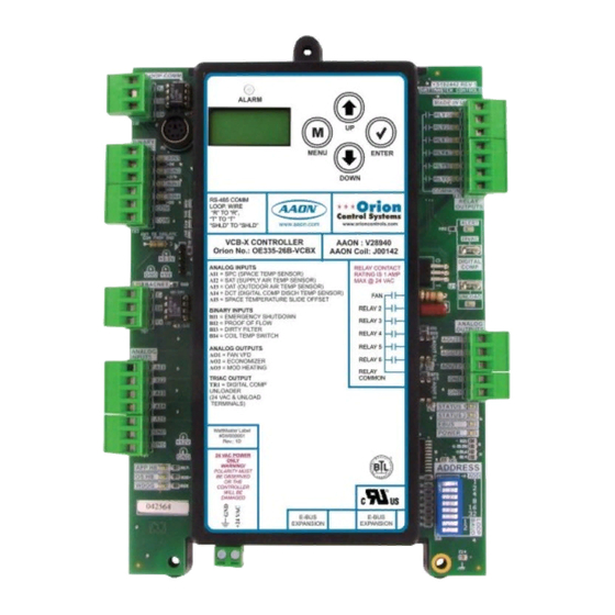
24 VAC POWER ONLY WARNING! LEDs Address Switch POLARITY MUST BE OBSERVED OR THE CONTROLLER WILL BE DAMAGED E-BUS E-BUS EXPANSION EXPANSION E-BUS E-BUS Connection Connection 24 VAC Power Input Figure 5: VCB-X Controller w/Enclosure Components VCB-X Controller Field Technical Guide... -
Page 19: Installation & Wiring
VCB-X Controller or the Expansion Modules. See Figures is a good idea to be familiar with the system wiring, no matter if it 6 & 7 for VCB-X input and output wiring. See Figures 22 & 23 for was factory or fi eld wired. -
Page 20: Vcb-X Input And Output Wiring
See Figures 6 & 7 for wiring details. Detailed wiring for all inputs and outputs are found on the pages that follow. The VCB-X Controller is designed with 5 analog inputs, 3 analog outputs, 1 triac output, 4 binary inputs and 6 relay outputs. - Page 21 INSTALLATION & WIRING VCB-X Controller Output Wiring VCB-X Controller Outputs Also please note that when wiring the VCB-X Controller, its contacts must be wired as wet contacts (connected to 24 VAC). The VCB-X Controller must be connected to 24 VAC as shown in the wiring diagram below.
-
Page 22: E-Bus Digital Room Sensor
Temperature and Humidity. The OE217-04 has no LCD display or E-BUS Hub or Adapter Board may be required. keypad. The Sensor connects to the VCB-X Controller with the EBC E-BUS expansion cable. It can also be daisy-chained with a CO... -
Page 23: E-Bus Co Wall Mounted Sensor
HVAC unit. The E-BUS CO of the Wall Mounted E-BUS CO Sensor. See Figure 10 for Duct Sensor connects to the VCB-X Controller with an EBC E-BUS Mounted E-BUS CO Sensor wiring details. -
Page 24: Duct Mounted E-Bus Co
OR THE CONTROLLER WILL BE DAMAGED E-BUS E-BUS EXPANSION EXPANSION VCB-X Controller 10 Foot EBC EBC E-BUS E-BUS Cable Cable (Provided) with Jack Connection Figure 10: OE256-07 - Duct Mounted E-BUS CO Sensor Wiring VCB-X Controller Field Technical Guide Revised 4/30/12... -
Page 25: Space Temperature Sensor & Slide Adjust
fl oor in the space that is to be controlled. VCB-X Controller OE210, OE211, OE212, OE213 Space Temperature Sensor Wire Required For Sensors With Slide Adjust Option Only Figure 11: OE210, OE211, OE212, OE213 – Space Temperature Sensor Wiring and Slide Adjust VCB-X Controller Field Technical Guide... -
Page 26: Supply Air Temperature Sensor
See Figure 12 below for details. VCB-X Controller OE231 Supply Air Temperature Sensor Mount In HVAC Unit Supply Air Duct Figure 12: OE231 – Supply Air Temperature Sensor Wiring VCB-X Controller Field Technical Guide... -
Page 27: Outdoor Air Temperature Sensor
E-BUS Outside Air & Humidity Sensor must be used instead. See Figure 14 for details. The OE250 Outdoor Air Temperature Sensor must be wired as shown for proper operation of the VCB-X Controller. The Outdoor Air Temperature Sensor is a 10K Type III thermistor sensor. The sensor CAUTION:... -
Page 28: E-Bus Outdoor Air Temperature And Humidity Sensor
The OE265-15-A (Horizontal) or OE265-16-A (Vertical) E-BUS HVAC unit rain hood is normally a good Outdoor Air Temperature & Humidity Sensor connects to the VCB-X location. Unused conduit opening(s) must Controller. A 10 foot EBC E-BUS cable (provided) plugs into the have closure plugs installed and must be coated Sensor’s attached 3 foot cable and then plugs into the E-BUS port... -
Page 29: E-Bus Return Air Temperature And Humidity Sensor
(provided) plugs into the Sensor’s attached 3 foot cable and have closure plugs installed and must be coated then plugs into the E-BUS port of the VCB-X Controller or other with sealing compound to provide a rain-tight E-BUS Expansion Board. The sensor should be mounted in the seal. -
Page 30: Suction Pressure Transducer Kit
Dehumidifi cation. required. The EBC E-BUS Cable connects to the E-BUS Adapter Board. This cable must then connect to the VCB-X Controller directly The Suction Pressure Transducer is used to measure suction pressure or to a VCB-X Expansion Board connected to the VCB-X Controller. -
Page 31: Digital Compressor Discharge Temperature Sensor
A Digital Compressor Discharge Temperature Sensor (by others) must be wired as shown in Figure 17 below for proper operation of the VCB-X Controller’s Digital Scroll Compressor. The Discharge Temperature Input is a thermistor input. There is no polarity requirement for the thermistor. -
Page 32: Digital Compressor Unloader
0.5A and the peak inrush current is 6A. The Digital Compressor Unloader uses a solenoid unloader as the Only (1) Digital Compressor can be controlled with the VCB-X capacity control method. The unloader solenoid is energized in an on/ Controller. -
Page 33: Supply Fan Vfd Signal
The Supply Fan VFD Signal is a user-adjustable signal with a range propagated on other electronic equipment. Use shielded wire of 0-10 VDC from AOUT1 on the VCB-X Controller. This signal wherever possible and route all sensor and controller wiring... -
Page 34: Economizer Damper Actuator
AOUT2) is user-adjustable, but must be set to 2-10 VDC for this polarity will result in damage to the actuator application. This signal output is used by the VCB-X Controller or VCB-X Controller. to modulate the Economizer Damper Actuator in order to control the amount of Outdoor Air delivered to the HVAC unit for Free Cooling and/or Indoor Air Quality requirements. -
Page 35: Modulating Heating Device
Modulating for either Direct Acting or Reverse Acting operation as required. Heating Device or the VCB-X Controller. The Output signal is normally used to control a Modulating Hot Water Valve or Modulating Steam Valve or is used for SCR Control of an Electric Heating Coil. -
Page 36: Em1 Expansion Module Input And Output Wiring
Zone VCB-X EM1 Expansion Module Input Wiring VCB-X EM1 Expansion Module Inputs The VCB-X EM1 Expansion Module can be used in conjunction with the VCB-X EM2 Expansion Module ( OE336-23-EM2-A) and The VCB-X EM1 Expansion Module ( OE336-23-EM1-A) provides the E-BUS 12-Relay Expansion Module (OE358-23E-12R-A). The... - Page 37 VCB-X EM1 Expansion Module Output Wiring VCB-X EM1 Expansion Module Outputs Also, please note that when wiring the VCB-X EM1 Expansion Module, its contacts must be wired as wet contacts (connected to The VCB-X EM1 Expansion Module must be connected to 24 24 VAC).
-
Page 38: Static Pressure Transducer
Static Pressure Transducer CAUTION: It is strongly recommended that you use pneumatic The OE271 Static Pressure Transducer plugs directly into the VCB-X tubing instead of relocating the sensor. Extending the wires could cause voltage drop problems. EM1 Expansion Module’s Static Pressure port. The Duct Static Pressure Sensor reading is used to determine current Duct Static Pressure. -
Page 39: Return Air Temperature Sensor
Air Duct Size Transformer For Correct Total Load. VCB-X E 1 Connect To Connect To Module = 5 VA VCB-X Controller Expansion Module(s) (When Used) Figure 25: OE231 Return Air Temperature Sensor Wiring Diagram VCB-X Controller Field Technical Guide Revised 7/30/13... -
Page 40: Leaving Water Temperature Sensor
Size Transformer For Correct Total Load. VCB-X E 1 Connect To Connect To Module = 5 VA VCB-X Controller Expansion Module(s) (When Used) Figure 26: OE230 and OE233 Leaving Water Temperature Sensor Wiring Diagram VCB-X Controller Field Technical Guide Revised 7/30/13... - Page 41 Thermal Mastic Between Pipe And Sensing Element. Pipe Should Be Clean And Smooth To Provide Proper Thermal Contact With Sensing Element. Thermal Mastic Strip (Supplied) Figure 27: OE233 Strap-On Leaving Water Temperature Sensor Installation VCB-X Controller Field Technical Guide Revised 9/18/13...
-
Page 42: Building Static Pressure Sensor
HVAC Unit the Building Static Pressure Sensor. Connect the power side of the Controller, Building Static Pressure Sensor, and the VCB-X Expansion Module. 24 VAC power source to the terminal labeled “+ EXC.” Connect the GND side of the 24 VAC power source to the terminal labeled “- COM.”... -
Page 43: Head Pressure Transducer
TRANSDUCER (BY OTHERS) Size Transformer For Correct Total Load. VCB-X E 1 Connect To Connect To Module = 5 VA VCB-X Controller Expansion Module(s) (When Used) Figure 29: Head Pressure Transducers Wiring Diagram VCB-X Controller Field Technical Guide Revised 7/16/14... -
Page 44: Building Pressure Control Output
Reverse Acting operation. A The Building Pressure Control Output is a 0-10 VDC or 2-10 VDC Building Pressure Sensor connected to SIG1 on the VCB-X EM1 signal sent from the VCB-X EM1 Expansion Module. When using... -
Page 45: Chilled Water Valve Actuator
Chilled Water Valve Actuator AOUT2 (By Others) 1 - COM 3 Y1 Line Voltage 24VAC Size Transformer For Correct Total Load. VCB-X E 1 Module = 5 VA Figure 31: Chilled Water Valve Actuator Wiring Diagram VCB-X Controller Field Technical Guide Revised 7/30/13... -
Page 46: Condenser Fan Ecm Motor And Vfd Or Water Valve Actuator Wiring
On an Air Cooled Unit, the Condenser Fan will be controlled with 0-10 VDC output signal or a PWM output signal. Both outputs The VCB-X EM1 Expansion Module can monitor up to (2) Head operate simultaneously. On a Water Cooled Unit, the Condenser Pressure Transducers and control up to (2) Condenser Fans or Water Valve will be controlled with a 2-10 VDC output signal. -
Page 47: Em2 Expansion Module Input And Output Wiring
Also please note that when wiring the VCB-X EM2 Expansion Module, its contacts must be wired as wet contacts (connected to The VCB-X EM2 Expansion can be used in conjunction with the 24 VAC). VCB-X EM1 Expansion Module ( OE336-23-EM1-A) and the E-BUS 12-Relay Expansion Module (OE358-23E-12R-A). -
Page 48: Remote Sat Reset Signal
VCB-X Controller applications. Title 24 Economizer Feedback This input on the VCB-X EM2 Expansion Module can accept a confi gurable voltage signal from 0-10 VDC (Direct or Reverse If the controller has been confi gured for Title 24 Economizer Acting). -
Page 49: Return Air Bypass
DPAC control scheme provides improved moisture ® removal capabilities and tighter temperature control than the AAON ® The VCB-X Controller can be confi gured for AAON ® PAC or PAC controls scheme by combining Copeland Digital Scroll™ DPAC applications. Both AAON PAC and DPAC control schemes ®... -
Page 50: E-Bus 12 Relay Expansion Module Wiring
12-Relay E-BUS Expansion Module Wiring E-BUS 12-Relay Expansion Module The E-BUS 12-Relay Expansion Module can be used in conjunction with the VCB-X EM1 Expansion Module ( OE336-23-EM1-A) and The E-BUS 12-Relay Expansion Module ( OE358-23E-12R-A) the VCB-X EM2 Expansion Module ( OE336-23-EM2-A). The provides for 12 Dry Contact Confi... -
Page 51: Ebtron ® , Greentrol™, And Paragon Air Flow Measurement Digital Transmitter
Contact WattMaster Controls for infor- the Parity to “NO PARITY, 1 STOP BIT.” mation on other airfl ow station options. The OE365-15-EBA E-BUS Adapter Board attaches to the VCB-X Controller with an EBC E-BUS cable. The Adapter Board is used for connecting the EBTRON , GreenTrol , or Paragon Airfl... -
Page 52: Mhgrv-X Controller
HGR Valve #1 EBC E-BUS Cable Connects To The VCB-X Controller’s Expansion Port Directly or Indirectly Using an 40 VA E-BUS Expansion Board Transformer Minimum Line Figure 38: MHGRV-X Controller to VCB-X Controller Wiring VCB-X Controller Field Technical Guide Revised 8/29/13... -
Page 53: Modgas-X Controller
24 VAC Power Connects To Input Terminals VCB-X Controller’s Expansion Max. Power Port Consumption 1 Gas Valve = 18 VA 2 Gas Valves = 33 VA Figure 39: MODGAS-X Controller to VCB-X Controller Wiring Diagram VCB-X Controller Field Technical Guide Revised 8/29/13... -
Page 54: Start-Up & Commissioning
fi rst time is to confi rm proper voltage and transformer is very important to correctly address the controller and run through sizing for each controller. Each VCB-X Controller requires 8 VA of a few simple checks. -
Page 55: Programming The Controller
Confi guration, see Appendices B & C. ® Controller, you must use an operator interface. Three different operator interfaces are available for programming and monitoring of the VCB-X Controller. See Figure 41. They are as follows: • Modular Service Tool SD •... -
Page 56: Inputs & Outputs
Zone VCB-X Controller and Expansion Module Input/Output Maps Input/Output Map VCB-X EM1 EXPANSION MODULE See Table 2 for the VCB-X Controller’s Input/Outputs, Table 3 for Analog Inputs the VCB-X EM1 Expansion Module’s Inputs/Outputs, and Table 4 Static Pressure (AI1) for the VCB-X EM2 Expansion Module’s Inputs/Outputs. - Page 57 Digital Compressor to protect contacts, the contact closure will not be recognized. against overheating. All Binary Inputs are optional. This means that you must confi gure the VCB-X Controller to recognize these input signals. VCB-X Controller Field Technical Guide...
- Page 58 If confi gured, this relay will energize anytime the space sensor Pushbutton override is active. Alarm Active If confi gured, this relay will energize anytime a VCB-X alarm is active. Morning Warm-Up / Cool- Confi gure (1) Relay for Morning Warm-Up / Cool-Down when Non-Orion VAV/Zone Controllers are Down (VAV Boxes) used.
- Page 59 VCB-X EM1 Expansion Module Inputs & Outputs VCB-X EM1 Expansion Module SIG1 - Building Static Pressure Sensor Input This Sensor is only required if you wish to confi gure the VCB-X AI1 - Duct Static Pressure Sensor Input Controller for Building Pressure Control. Building Pressure...
- Page 60 A wet contact closure on this input is used to provide a means for This is a direct acting output signal that is used to modulate the another BAS or control device (by others) to force the VCB-X Condenser Fan VFD (0-10 VDC signal) on an Air Cooled unit. It Controller into Dehumidifi...
-
Page 61: Sequence Of Operations
When the Remote Forced Occupied Signal is removed, the controller Dehumidifi cation. will revert to the Unoccupied Mode of operation, or if an internal VCB-X schedule is also being used, it will revert back to the current scheduled mode. HVAC Source Confi guration Options Setting the Internal Week Schedule to ‘0’... -
Page 62: Hvac Modes Of Operation
Compressor will stage on and modulate to control to the Active • Heating Mode Supply Air Cooling Setpoint. One Digital Compressor can be • Vent Mode controlled with the VCB-X Controller. • Dehumidifi cation Mode • Heat Pump If additional cooling is required, fi xed compressor stages can be •... -
Page 63: Economizer Operation
Dehumidifi cation Operation Dehumidifi cation Mode For DX Cooling Stages, the VCB-X activates the Cooling Stages On VAV, CAV, Single Zone VAV, and High Percentage Outdoor based on the actual Evaporator Coil Temperature compared to Units with Space Temperature Control, the Dehumidifi cation Mode the Evaporator Coil Temperature Setpoint. - Page 64 Mode section. When Heating is used to supplement Hot Gas Reheat, extract moisture from the Supply Air and utilizes either Modulating the VCB-X restricts the Heating to one form of Modulating Heat or Hot Gas Reheat, On/Off Hot Gas Reheat, or Heating to reheat the one stage of Gas or Electric Heat.
-
Page 65: Heating
Heating Setpoint. Heating is disabled Primary and Secondary Heating when the Mode Enable temperature raises one deadband above the The VCB-X can activate two forms of Heating, which are classifi ed Heating Setpoint. as Primary and Secondary Heat Sources. The following section describes that operation. -
Page 66: Remote Contact Control
Level Setpoint, the Economizer Minimum Position will be reset to the Maximum Reset Position. A Remote Contact Control option can be confi gured on the VCB-X 3. The Maximum Reset Position Setpoint is the highest Controller to initiate the HVAC Modes of operation. If this option is the Economizer Minimum Position can be reset to during confi... -
Page 67: Single Zone Vav
Heating and the Cooling Modes. The EM2 Expansion Module the Supply Fan will run at the set Maximum VFD Heating Speed is required for this option. (100% default) and Heating will occur as described in the Heating Section of this sequence. VCB-X Controller Field Technical Guide Revised: 4/21/14... -
Page 68: Airfl Ow Monitoring
Duct Static Pressure Control Airfl ow Monitoring If the VCB-X Controller has been confi gured for Duct Static Pressure Outdoor, Supply, Return and Exhaust Airfl ow can be monitored Control, then anytime the Supply Fan is operating, the unit will be... -
Page 69: Duct Static Pressure Control For Filter Loading
Sensor (used to monitor the discharge pressure) in conjunction with Pressure Setpoint. Whenever the Building Pressure a Supply Fan VFD. If the fi lters are getting dirty, the VCB-X will falls below the Building Pressure Setpoint by the ramp up the VFD to compensate for the decrease in airfl ow. To utilize Deadband amount, the modulating Economizer Output this feature, the unit must be confi... -
Page 70: Cav/Mua Dual Mode (Hood On/Off Operation)
So, if dehumidifi cation is confi gured and the humidity is above setpoint, the unit will be in Vent Mode Dehumidifi cation The VCB-X Controller can be confi gured as a CAV controller but (see the Dehumidifi cation Mode section for more details). Reheat switch to MUA operation when an exhaust hood is energized. -
Page 71: Air To Air Heat Pump Operation
Cooling Mode will operate in the same manner as described in the Cooling section. If using the VCB-X Controller with an installed Defrost Coil Temperature Switch, a Defrost Cycle is available. A reversing valve relay output can be confi gured to activate with the fi... -
Page 72: Water Source Heat Pump Operation
Any digital compressor stage in a Heat Pump unit must the fi rst compressor stage in the Heating Mode or the Cooling Mode be confi gured as a “Digital Compressor”. The VCB-X of operation. will know it will operate as a heat pump compressor by the unit being confi... -
Page 73: Water Source Heat Pump Safety Monitoring
If the Suction Pressure falls below the Unsafe Suction Pressure Compressors will not be enabled. Setpoint for 5 seconds: • The VCB-X will wait up to 3 minutes to activate the POF Alarm and the POF LEDs which will • Compressors will be locked out immediately. -
Page 74: Head Pressure Control
An Outdoor Air Temperature Sensor reading is broadcast from 30 seconds on an Air Cooled Unit and at 75% for 3 minutes on a any one VCB-X Controller to any controller that does not have an Water Cooled Unit. Outdoor Air Temperature Sensor. -
Page 75: Sensor Failure Alarms
Compressor Discharge Sensor Failure Alarm This alarm is generated if the unit is confi gured to have a digital scroll compressor, but the Digital Compressor Discharge Temperature Sensor is not detected or if shorted. VCB-X Controller Field Technical Guide... -
Page 76: Failure Mode Alarms
Smoke Detector, Firestat, or other shutdown condition occurs. If If the unit runs for 60 minutes without a digital compressor discharge this contact opens, it will initiate shutdown of the VCB-X and will temperature alarm, then the counter is reset to zero. -
Page 77: Vav/Zone Controller Alarms
Economizer is enabled but not following the desired Economizer position commanded. There are 5 relay outputs that are confi gurable for the VCB-X Controller (Relay #1 is reserved for the Supply Fan and is not Economizer Is Economizing When It Should Not confi... -
Page 78: Troubleshooting
BACnet communications. COMM - Every time the module receives a valid E-BUS request from the VCB-X Controller, this LED will blink on and then off, signifying that it received a valid request and responded. VCB-X Controller Field Technical Guide... -
Page 79: Vcb-X Controller & Vcb-X Em1 Expansion Module Led Locations
1002 SIG2 10uF AOUT3 AOUT4 PRESSURE SENSOR INPUTS BIN1 PWM- BIN2 1002 PWM+ BIN3 1002 BINARY INPUTS 1002 OPTIONS 1002 ADDRESS .01uF Figure 42: VCB-X Controller & VCB-X EM1 Expansion Module LED Locations VCB-X Controller Field Technical Guide Revised: 2/14/14... -
Page 80: Led Operation
Blink Code Description Blinks Blinks POWER LED Operation When the VCB-X Controller is fi rst powered up, the POWER LED NORMAL OPERATION should light up and stay on continuously. If it does not light up, SUPPLY AIR SENSOR FAILURE check to be sure that you have 24 VAC connected to the controller,... -
Page 81: Appendix A
Interconnected System The Interconnected System is used when you have multiple VCB-X The VCB-X Controller can be used as a Stand-Alone System (one Controllers on your job. With this system, you simply connect the VCB-X Controller only), connected together on an Interconnected... - Page 82 APPENDIX A Zone Stand-Alone System Layout Operator Interfaces Modular System Manager SD Modular Service Tool SD System Manager Touch Screen II Personal Computer, CommLink, and Prism 2 Software Figure 44: Typical Stand-Alone System Layout VCB-X Controller Field Technical Guide Revised 9/24/13...
- Page 83 APPENDIX A Interconnected System Layout VCB-X Controller Field Technical Guide Revised 9/24/13...
- Page 84 Zone APPENDIX A Zone Networked System Layout VCB-X Controller Field Technical Guide Revised 9/24/13...
-
Page 85: Space, Outdoor Air Or Return Air Temperature Sensor Testing
If the voltage is above 4.88 VDC, then the sensor or wiring is “open.” 22.22 11136 2.635 If the voltage is less than 0.05 VDC, then the sensor or wiring is 22.77 10878 2.605 shorted. Table 8: Temperature/Resistance for Type III 10K Ohm Thermistor Sensors VCB-X Controller Field Technical Guide... -
Page 86: Copeland ® Discharge Thermistor Temperature Sensor Testing
If the voltage is above 4.98 VDC, then the sensor or wiring is “open.” 17.91 3.20 If the voltage is less than 0.38 VDC, then the sensor or wiring is shorted. 15.07 3.00 12.73 2.80 10.79 2.59 9.20 2.39 Table 9: Discharge Thermistor Temperature/ Resistance VCB-X Controller Field Technical Guide... -
Page 87: Oe271 & Oe258-01 Pressure Sensor Testing
DC volts. Place the “-” (minus) lead on terminal labeled GND and the “+” lead on terminal AIN4 on the Analog Input/Output removed. Be sure to replace the jumper after checking. Expansion Module. VCB-X Controller Field Technical Guide Revised 4/9/12... -
Page 88: Oe275-01 Suction Pressure Transducer Testing
DC volts. Place the positive lead from 24.49 87.16 61.17 174.32 the meter on the PR OUT terminal located on the VCB-X Expansion 27.80 93.39 63.19 180.55 Module terminal block. Place the negative lead from the meter on the ground (GND) terminal located adjacent to the PR OUT terminal 30.99... -
Page 89: Head Pressure Transducer Troubleshooting
Head Pressure Transducer Troubleshooting If you suspect there is a problem related to head pressure transducer measurements, reference Table 13 below. Head Pressure Transducer Chart Voltage Pressure Voltage Pressure Table 13: Head Pressure Transducer Chart VCB-X Controller Field Technical Guide Revised 4/9/12... -
Page 90: Appendix B - Lcd Display Screens (Controller Interface & Bacnet ® Confi Guration)
Use this key to adjust setpoints and change DOWN confi gurations. Use the ENTER key to navigate through the ENTER Main Menu Screen categories. Figure 47: LCD Display and Navigation Keys Table 14: Navigation Key Functions VCB-X Controller Field Technical Guide Revised: 4/24/13... - Page 91 - CURRENT BAUD RATE 9600, 19200, 38400, 57600, 76800. Default is 38400. Status EBUS Press to scroll through Status Screens. Hi Speed E-BUS COMMUNICATIONS Hi Speed or Lo Speed. Default is Hi Speed. VCB-X Controller Field Technical Guide Revised: 4/24/13...
- Page 92 Status Spc RH X.X % FORCE OCC MODE SPACE HUMIDITY MODE This screen displays the current mode of operation of the VCB-X Controller. The mode options are: Sat Temp XX.X LINE 1 • UNOCCUPY (Unoccupied) SUPPLY AIR TEMPERATURE • OCCUPIED 40ºF to 200ºF or 5ºC to 93ºC.
- Page 93 REHEAT ALARM what the alarm is. Reheat Board Missing, page 75. See Missing Expansion Module Alarm - MODGAS ALARM MODGAS Board Missing, page 75. See Missing Expansion Module Alarm, RLY EXP ALARM page 75. VCB-X Controller Field Technical Guide Revised: 8/19/14...
- Page 94 Default is -1.0 = AUTO. ExpRly 1-5 ON, OFF, AUTO Cooling -1.0, 0.0-10.0 VCB-X EM1 EXPANSION RELAYS 1-5 Press the <UP> button to change the value. Default is AUTO. MODULATING COOLING 0.0 to 10.0 = Active Force Mode. Press the <UP> and <DOWN> buttons to increase and decrease the value.
-
Page 95: Appendix C - Vcb-X Bacnet ® Connection To Ms/Tp Network, Bacnet Parameters & Pics Statement
1.) All wiring to be in accordance with local and national electrical codes and specifications. 2.) All communication wiring to be 18 gauge minimum, 2 conductor twisted pair with shield. Use Belden #82760 or equivalent. Figure 48: VCB-X BACnet Connection to MS/TP Network VCB-X Controller Field Technical Guide... - Page 96 APPENDIX C - VCB-X BACnet ® VCB-X BACnet Parameters ® BACnet Properties for the VCB-X Controller BACnet Properties for the VCB-X Controller ® ® Parameter Object Description Limits Parameter Object Description Limits Application AI: 1 Current version of the Outdoor AI: 22 Current Outdoor Airfl...
- Page 97 APPENDIX C - VCB-X BACnet ® VCB-X BACnet Parameters ® BACnet Properties for the VCB-X Controller BACnet Properties for the VCB-X Controller ® ® Parameter Object Description Limits Parameter Object Description Limits Condenser 1 AI:39 Condenser 1 Fan / Water...
- Page 98 APPENDIX C - VCB-X BACnet ® VCB-X BACnet Parameters ® BACnet Properties for the VCB-X Controller ® BACnet Properties for the VCB-X Controller ® Parameter Object Description Limits Parameter Object Description Limits Max SAT AV: 13 If Supply Air Reset is con-...
- Page 99 APPENDIX C - VCB-X BACnet ® VCB-X BACnet Parameters ® BACnet Properties for the VCB-X Controller BACnet Properties for the VCB-X Controller ® ® Parameter Object Description Limits Parameter Object Description Limits SAT Cool AV: 33 If doing Supply Air Setpoint...
- Page 100 APPENDIX C - VCB-X BACnet ® VCB-X BACnet Parameters ® BACnet Properties for the VCB-X Controller ® BACnet Properties for the VCB-X Controller ® Parameter Object Description Limits Parameter Object Description Limits Outdoor Air AV:60 Controls rate of change 9999...
- Page 101 APPENDIX C - VCB-X BACnet ® VCB-X BACnet Parameters ® BACnet Properties for the VCB-X Controller BACnet Properties for the VCB-X Controller ® ® Parameter Object Description Limits Parameter Object Description Limits Reheat BI:4 Modulating Hotgas Reheat Bad or BI: 20...
- Page 102 APPENDIX C - VCB-X BACnet ® VCB-X BACnet Parameters ® BACnet Properties for the VCB-X Controller ® BACnet Properties for the VCB-X Controller ® Parameter Object Description Limits Parameter Object Description Limits Low Control BI: 29 Occurs when the Control-...
- Page 103 APPENDIX C - VCB-X BACnet ® VCB-X BACnet Parameters ® BACnet Properties for the VCB-X Controller BACnet Properties for the VCB-X Controller ® ® Parameter Object Description Limits Parameter Object Description Limits 12 Relay BI:57 Current status of Relay 10...
- Page 104 APPENDIX C - VCB-X BACnet ® VCB-X BACnet Parameters ® VCB-X BACnet Property Identifi er: ® Bad Supply CFM Sensor (10), Bad Return CFM Sensor (11), Bad or Missing Reheat Module (12), BACNETPropertyIdentifi er : Bad or Missing ModGas Module...
- Page 105 APPENDIX C - VCB-X BACnet ® BACnet PICS ® ® BACnet Protocol Implementation Conformance Statement Vendor Listing Status WattMaster Controls, Inc. Listed Product 8500 NW River Park Drive, Suite 108A Parkville, MO 64152 Test Requirements BACnet Protocol Revision Date Tested ®...
-
Page 106: Index
Building Static Pressure Sensor..10,42 Failure Mode Alarms..76 Wiring..42 High and Low Control Temp Failure..76 Building Static Pressure Sensor Input Description..59 High and Low Supply Temp Alarm..76 Building Static Pressure/Voltage Chart..87 High Space Temp Alarm..77 Bypass Damper Control..64 VCB-X Controller Field Technical Guide... - Page 107 Diagnostic LED Locations..79 Cooling Stage Relay Description..58 VCB-X Controller Input Wiring..20 VCB-X Controller Output Wiring..21 VCB-X EM2 Expansion Module Input Wiring..48 VCB-X EM2 Expansion Module Outputs Wiring..49 Damper Closing Alarm..77 VCB-X Expansion Module 1 Input Wiring..36 Damper Feedback Failure Alarm..77 VCB-X Expansion Module 1 Output Wiring..37...
- Page 108 EBC-XX-F..10 Fan Relay..56 Fan VFD..56 EBTRON Air Flow Measurement Digital Transmitter Wiring..51 EBTRON Airfl ow Station..68 Features, VCB-X Controller..5 Features and Applications, VCB-X Controller..5 E-BUS 12 Relay Expansion Module..8 E-BUS 12-Relay Expansion Module Field Wired..19 Filter Loading..69 Wiring..50 Filter Loading Applications..5 E-BUS Adapter..9...
- Page 109 ) Control Operation..66 Low Supply Temp Alarm LED Blinks..80 Immersion Well for OE230 Water Temperature Sensor..10 Initialization, System..55 Inputs, VCB-X Controller..57 Inputs and Outputs, VCB-X EM1 Expansion Module..59 Make-Up Air Unit..6 Input Wiring, VCB-X Controller..20 Maximum Reset Position Setpoint..66 Instructions, Addressing..54 Mechanical Cooling..62...
- Page 110 OE332-23-VCB-X Requirements..19 Morning Warm-up Heating..6 OE332-23-VCMX..19 Morning Warm-Up (VAV Boxes) Relay Description..58 OE335-23-VCBX-A..5,8 MS000248..12 OE336-23-EM1-A..5,8 MUA Unoccupied Operation..69 OE336-23-EM1-A VCB-X EM1 Expansion Module..36,47,50 OE336-23-EM2-A..8 OE358-23E-12R 12-Relay E-BUS Expansion Module..36,47,50 OE358-23E-12R-A..5,8 Wiring..50 Networked System Defi ned..81 OE361-13..11 Networked System Layout..84 OE364-22..11 Network System..81...
- Page 111 Reverse Acting Operation..35 Reversing Valve Relay Description..58 R1..58 Reversing Valve Relay Output..71,72 R22..5 RH Level R410A Refrigerant..88 VCB-X Controller..19 Reheat Relay Description..58 RLY1 LED Supply Fan..78 Relay Alarm Active..58 Room Sensor..8 Relay LEDs..78 Relay Outputs..77 VCB-X Controller Field Technical Guide...
- Page 112 Space Sensor Failure LED Blinks..80 Diagnostic LED Blink Code Interpretation..80 Space Sensor Failure Alarm..77 User-Confi gurable Relay Outputs..58 Space Sensor Operation..65 VCB-X Controller Inputs & Outputs..56 Space Slide Offset..56 Temperature Range for VCB-X Controller..19 Space Temperature..56 Temperature/Resistance Chart..85,86 Space Temperature Sensor Temperature/Resistance for Type III 10K Ohm Thermistor Diagram..25...
- Page 113 Wiring..36,37 VAV Cooling..67 VCB-X EM2 Expansion Module..8,60 VAV Dehumidifi cation..6 Dimensions..16 VAV Heating..67 Inputs and Outputs..56,60 VAV/Zone Controller Alarms..77 Output Wiring..49 VCB-X 12 Relay E-BUS Expansion Module Wiring..47,48 Described..8 Ventilation Mode..65 Dimensions..17 Vent Mode..62 Overview..5 VFD..33 VCB-X Controller..8 VFD Supply Fan..6 Alarms..74...
- Page 114 Supply Fan VFD Signal..33 Economizer Damper Actuator..34 VCB-X Controller..20,21 Entering Water Temperature Sensor..40 VCB-X EM2 Expansion Module..47,48 GND-to-GND..54 VCB-X EM2 Expansion Module Input..48 Head Pressure Transducer..43 VCB-X EM2 Expansion Module Outputs..49 Important Considerations..19 VCB-X Expansion Module..36 Leaving Water Temperature Sensors..40 VCB-X Expansion Module 1 Input..36...
- Page 115 NOTES VCB-X Controller Field Technical Guide...
- Page 116 Form: OR-VCBX-FIELD-TGD-01Q Printed in the USA August 2014 All rights reserved. Copyright 2014 WattMaster Controls Inc. 8500 NW River Park Drive Parkville, MO 64152 Phone: 866-918-1100 www.orioncontrols.com Fax (816) 505-1101...