Table of Contents
Advertisement
Quick Links
AUTOMATIC WELDING SYSTEMS
For use with machines having Code Numbers:
Safety Depends on You
Lincoln arc welding and cutting
equipment is designed and built
with safety in mind. However,
your overall safety can be
increased by proper installation
... and thoughtful operation on
your part. DO NOT INSTALL,
OPERATE OR REPAIR THIS
EQUIPMENT WITHOUT READ-
ING THIS MANUAL AND THE
SAFETY PRECAUTIONS CON-
TAINED THROUGHOUT. And,
most importantly, think before
you act and be careful.
World's Leader in Welding and Cutting Products
22801 St. Clair Ave. Cleveland, Ohio 44117-1199 U.S.A. Tel. (216) 481-8100
NA-3 AND NA-4
NA-3N
NA-3S
NA-4
SERVICE MANUAL
Sales and Service through Subsidiaries and Distributors Worldwide
SVM 121-A
Premier Manufacturer of Industrial Motors
June, 1997
Advertisement
Chapters
Table of Contents
Troubleshooting

Related Manuals for Lincoln Electric NA-3


Summary of Contents for Lincoln Electric NA-3
- Page 1 SVM 121-A June, 1997 NA-3 AND NA-4 AUTOMATIC WELDING SYSTEMS For use with machines having Code Numbers: NA-3N NA-3S NA-4 Safety Depends on You Lincoln arc welding and cutting equipment is designed and built with safety in mind. However, your overall safety can be increased by proper installation ...
- Page 2 Miami, Florida 33135 or CSA Standard W117.2-1974. A Free copy of “Arc Welding Safety” booklet E205 is available from the Lincoln Electric Company, 22801 St. Clair Avenue, Cleveland, Ohio 44117-1199. BE SURE THAT ALL INSTALLATION, OPERATION, MAINTENANCE AND REPAIR PROCEDURES ARE PER- FORMED ONLY BY QUALIFIED INDIVIDUALS.
-
Page 3: Safety
This can create fire hazards or overheat lifting chains or recommendations. cables until they fail. 6.c. Ground the equipment in accordance with the U.S. National 4.h. Also see item 7c. Electrical Code and the manufacturer’s recommendations. Mar. ‘93 NA-3 AND NA-4... - Page 4 ___________________________________________________ 7.h. To avoid scalding, do not remove the radiator pressure cap when the engine is hot. NA-3 AND NA-4...
- Page 5 épaisse, pan- talons sans revers, et chaussures montantes. place. 5. Toujours porter des lunettes de sécurité dans la zone de soudage. Utiliser des lunettes avec écrans lateraux dans les zones où l’on pique le laitier. Mar. ‘93 NA-3 AND NA-4...
- Page 6 NOTES NA-3 AND NA-4...
-
Page 7: Table Of Contents
Parts Manual ......... . . P-100 & P-114 NA-3 AND NA-4... -
Page 8: Installation Section
......A-11 Figure A.9: Connection of NA-3 (All) to an SAN ... . A-12 Figure A.10: Connection of NA-3 (All) to a SAM Motor-Generator... -
Page 9: Installation
INSTALLATION TECHNICAL SPECIFICATIONS – NA-3 AND NA-4 MINIMUM ELECTRICAL INPUT REQUIREMENTS 115 VAC @ 3 amps 50/60 Hz power REQUIRED WELDING POWER SOURCE NA-3N DC Constant Voltage NA-3S DC Constant Current or DC Constant Voltage NA-4 AC Constant Current WIRE FEED SPEED and GEAR RATIOS FEED SPEED RANGE MAX. - Page 10 HEAD MOUNTING PARTS (WITH INSULATION AND HARDWARE) CONTROL CROSS SEAM ADJUSTER 4 FT (1.2 M) CABLE (DRIVE MOTOR TO CONTROL BOX) WELDING HEAD CONTACT ASSEMBLY (OPTIONAL) 4 FT (1.2 M) ELECTRODE CABLES [(TWO 4/0) CONTACT ASSEMBLY TO CONTROL BOX] NA-3 AND NA-4...
-
Page 11: Mechanical Installation
Figure A.3. When placing the mounting holes, make sure you leave adequate ventilation space below the front cover to allow for the free circulation of cooling air. CARRIAGE NA-3 AND NA-4... -
Page 12: Welding Head Installation
4. Install the back cover of the control box. Standard head mounting hardware and insulation are shipped with the NA-3 and FIGURE A.3 – CONTROL BOX NA-4 welding heads. If you are mounting FIXTURE MOUNTING. the welding head on a separate fixture,... -
Page 13: Electrical Installation
(when facing the ELECTRICAL front of the control box) of the shunt on the NA-3 or to the current transformer on the NA- INSTALLATION 4 as shown in Figure A.6. When the K234 or... -
Page 14: Power Supply To Control Box Connections
Refer to Figures A.7 to A.18 for diagrams on how to connect the control box to a particular 6. Insert the polarized connector of the power source. If it is not a Lincoln Electric control cable into the matching power source, refer to Figure A.19 at the end receptacle on the side of the control of this section. -
Page 15: Na-3S
NOTE: Paralleling two power sources of the (K775). Refer to diagram S15667 in same model may be practical. Request the IM-283 manual or request it from bulletin E1.30 from Lincoln Electric for the factory. instructions. 3. Connect the input cable to the power 4. -
Page 16: Power Source Connection Diagrams
If it is not a Lincoln Electric power source, b. Route the weld cables into the refer to Figure A.19 at the end of this control box on the opposite side section. -
Page 17: Types "-O" Or "-Of" And M.g. Solid State Field Control
A-10 A-10 INSTALLATION FIGURE A.7 – CONNECTION OF NA-3 (ALL) TO A SAF-600 OR SA-800, TYPES “-O” OR “-OF” AND M.G. SOLID STATE FIELD CONTROL. WARNING TURN OFF INPUT POWER TO THE WELDING POWER SOURCE USING THE DISCONNECT SWITCH BEFORE WORKING ELECTRIC ON THIS EQUIPMENT. - Page 18 A-11 A-11 INSTALLATION FIGURE A.8 – CONNECTION OF NA-3 (SET FOR CONSTANT CURRENT WELDING) TO A SAF-600 OR SA-800, TYPE “-F” AND M.G. SOLID STATE FIELD CONTROL. WARNING TURN OFF INPUT POWER TO THE WELDING POWER SOURCE USING THE DISCONNECT SWITCH...
- Page 19 A-12 A-12 INSTALLATION FIGURE A.9 – CONNECTION OF NA-3 (ALL) TO AN SAN. WARNING TURN OFF INPUT POWER TO THE WELDING POWER SOURCE USING THE DISCONNECT SWITCH BEFORE WORKING ELECTRIC ON THIS EQUIPMENT. SHOCK CAN KILL N.A. ELECTRODE CABLE TO...
- Page 20 A-13 A-13 INSTALLATION FIGURE A.10 – CONNECTION OF NA-3 (ALL) TO A SAM MOTOR-GENERATOR OR ENGINE DRIVEN WELDER. WARNING TURN OFF INPUT POWER TO THE WELDING POWER SOURCE USING THE DISCONNECT SWITCH BEFORE WORKING ELECTRIC ON THIS EQUIPMENT. SHOCK CAN KILL...
-
Page 21: Line Voltage Compensator
#21 SHOULD BE TAPED TO THE WELDING WORK LEAD. N.D. NA-3 LEADS A, B, AND C (#75, #76, AND #77 ON OLDER K215 CONTROL CABLE) ARE TAPED UP WHEN THE R3S LINE VOLTAGE COMPENSATOR IS CONNECTED. ARC VOLTAGE IS CONTROLLED BY THE LINE VOLTAGE COMPENSATOR RHEOSTAT. THERE WILL BE NO ADJUSTMENTS OF VOLTAGE BY AUTOMATIC CONTROL BOX CONTROLS. - Page 22 A-15 A-15 INSTALLATION FIGURE A.12 – CONNECTION OF NA-3 TO R3S-400, 600, OR 800 WITH NO LINE VOLTAGE COMPENSATOR. WARNING TURN OFF INPUT POWER TO THE WELDING POWER SOURCE USING THE DISCONNECT SWITCH BEFORE WORKING ELECTRIC ON THIS EQUIPMENT. SHOCK CAN KILL N.D.
-
Page 23: Cv/Cvi Power Sources
A-16 A-16 INSTALLATION FIGURE A.13 – CONNECTION OF NA-3 TO IDEALARC DC-400 AND TO CV/CVI POWER SOURCES. WARNING TURN OFF INPUT POWER TO THE WELDING POWER SOURCE USING THE DISCONNECT SWITCH BEFORE WORKING ELECTRIC ON THIS EQUIPMENT. SHOCK CAN KILL POWER SOURCE N.F. - Page 24 A-17 A-17 INSTALLATION FIGURE A.14 – CONNECTION OF NA-3 TO IDEALARC DC-1000 AND DC-1500. WARNING TURN OFF INPUT POWER TO THE WELDING POWER SOURCE USING THE DISCONNECT SWITCH BEFORE WORKING ELECTRIC ON THIS EQUIPMENT. SHOCK CAN KILL N.D. TO AUTOMATIC CONTROL BOX POWER SOURCE N.E.
-
Page 25: Current Control) To An Ac-1000
ELECTRICALLY SEPARATE FROM THE WELDING WORK LEAD CIRCUIT AND CONNECTION. FOR CONVENIENCE, THIS EXTENDED LEAD #21 SHOULD BE TAPED TO THE WELDING WORK LEAD. N.C. TAPE UP BOLTED CONNECTIONS. N.D. IF USING AN OLDER CONTROL CABLE, TAPE ENDS OF LEADS #75, #76, AND #77. CLEVELAND, OHIO U.S.A NA-3 AND NA-4... -
Page 26: Current Control) To An Ac-1200
N.C. IF USING AN OLDER CONTROL CABLE, CONNECT LEADS #75, #76, AND #77 TO LEADS #75, #76, AND #77 OF THE TERMINAL STRIP, RESPECTIVELY. N.D. TO AVOID POSSIBLE INDUCED NA-4 METER READING ERROR, KEEP THE CONTROL LEADS, INCLUDING THE EXTENDED LEAD #21 SEPARATED FROM THE AC WELDING CABLES BY AT LEAST 12 IN. (305 MM). CLEVELAND, OHIO U.S.A NA-3 AND NA-4... - Page 27 A-20 A-20 INSTALLATION FIGURE A.17 – CONNECTION OF NA-3 TO SAF-600 “F” OR SA-800 “F” AND M.G. SOLID STATE FIELD CONTROL AND K240 CONTACTOR KIT. WARNING TURN OFF INPUT POWER TO THE WELDING POWER SOURCE USING THE DISCONNECT SWITCH BEFORE WORKING ELECTRIC ON THIS EQUIPMENT.
- Page 28 A-21 A-21 INSTALLATION FIGURE A.18 – CONNECTION OF NA-3 TO IDEALARC DC-600. WARNING TURN OFF INPUT POWER TO THE WELDING POWER SOURCE USING THE DISCONNECT SWITCH BEFORE WORKING ELECTRIC ON THIS EQUIPMENT. SHOCK CAN KILL POWER SOURCE TO AUTOMATIC CONTROL BOX...
- Page 29 REFER TO THE POWER SOURCE WIRING DIAGRAM TO FIND THE TYPE OF CONTACTOR CIRCUIT. THE MAXIMUM RATING OF THE NA-3 TERMINAL #2 TO TERMINAL #4 CIRCUIT IS 3 AMPS 125 VAC AT FULL LOAD AND STEADY STATE. *600 VAC IF THE LINCOLN ELECTRIC CO. TRAVEL CARRIAGE IS CONNECTED TO THE NA-3. THERE WILL BE NO OUTPUT CONTROL OF THE POWER SOURCE AT THE NA-3.
- Page 30 Available Starting Sequences ......B-14 Setting Travel Starting and Stopping ..... B-14 NA-3 AND NA-4...
-
Page 31: Operating Instructions
Once the system is properly set up, the nozzle wears during repetitive welding, it operator can make production welds must be replaced. Check the contact tip for without readjusting the controls using the wear weld quality seems following simple instructions: deteriorating. NA-3 AND NA-4... -
Page 32: Controls And Their Functions
“Automatic Welding” for welding operations. 4. CURRENT CONTROL. Adjusts wire feed speed to control welding current. 10. VOLTAGE CONTROLS. Adjusts arc volts by controlling power source output voltage. FIGURE B.1 – NA-3N CONTROLS. 5A 5B NA-3 AND NA-4... -
Page 33: Na-3S (When Connected To A Constant Current Power Source
Figures B.1 and B.2 for all other controls. Older NA-4s used with AC-1000 power sources use a toggle switch instead of a rheostat for current control. CURRENT CONTROL. Adjusts welding current by controlling power source output. NA-3 AND NA-4... -
Page 34: Inner Control Panel
6. TIME DELAY. Prevents crater speeds. sticking by adjusting the time for 2. FUSES. Located on the control PC electrode burnback and/or retraction board behind the inner panel door. from the puddle. FIGURE B.4 – INNER CONTROL PANEL. NA-3 AND NA-4... -
Page 35: Setting For Cv Or Cc Power Sources
CURRENT source being used is on top. BOARD 4. If the optional start controls or crater JUMPER controls PC boards are installed, make sure the correct nameplates for the power supply being used are on top. NA-3 AND NA-4... -
Page 36: Welding With Dc Constant Voltage (Cv
[DC(+) or DC(-)] Figure B.6. specified procedures. Interchange the NA-3 voltmeter and 4. The mount for standard 50 and 60 lb ammeter leads if the polarity was (22.7 and 27.2 kg) electrode coils changed. If using the discontinued... -
Page 37: Control Adjustments And Test Welding
Submerged Arc” as appropriate sequences and the rewiring needed for the process and procedure. to accomplish them. d. Set the NA-3 “Inch Speed” control at “2”. CONTROL ADJUSTMENTS AND TEST WELDING e. DC-600 – Set the “OCV Control”... - Page 38 OPERATING INSTRUCTIONS For further information on using these SAN with Discontinued Solid State power sources with NA-3, refer to the Remote Field Control DC-600, DC-1000, or DC-1500 a. Set the power source “Voltage” operating manuals. rheostat to maximum. Idealarc DC-400 b.
- Page 39 9. Connect the work lead to the work or needed for the application. a suitable piece of scrap. Clip the end d. Set the “Contactor and Electrode of the electrode to a sharp point. Back Up Time Delay” to provide the stopping characteristics needed. NA-3 AND NA-4...
-
Page 40: Welding With Dc Or Ac Constant Current (Cc
Reverse 3. If using a K148 or K226 Contact the NA-3 or NA-4 voltmeter and Assembly, rotate the assembly ammeter leads if the polarity was relative to the direction of travel as changed. -
Page 41: Control Adjustments And Test Welding
Set the 3-position toggle switch to SAF-600 and SA-800 with Discontinued “VV Submerged Arc.” Solid State Remote Field Control d. Set the NA-3 “Inch Speed” at “2”. a. Set the “Voltage Range” switch on the power source to “High.” e. Set the “OCV Control” near minimum. - Page 42 Circuit Voltage” control on the inner carriage control panel. panel of the NA-3. Set the “OCV 8. Mount and properly connect the work Control” for good striking at about lead to the work or a suitable piece of 3 to 8 volts higher than the welding scrap.
-
Page 43: Starting And Stopping Sequences
Hot Starting stopping sequences. 1. With the electrode not touching the *With the NA-4 and discontinued AC-1000 or AC-750 work, press the “Start” button. combination, the current is not adjustable. NA-3 AND NA-4... - Page 44 “Standstill” Travel Starting All models can be reconnected so the travel remains at a standstill until the arc starts. FIGURE B.8 – LOGIC BOARD TRAVEL SEQUENCE CONNECTIONS OR SWITCH POSITIONS. NEWER LOGIC BOARD OLDER LOGIC BOARD P4 P9 NA-3 AND NA-4...
- Page 45 3. The arc continues to burn the Electrode Back Up Time Delay.” The “Inch electrode back from the puddle until Speed” set for good arc striking also affects the time set on the “Contactor and the distance the wire is retracted. JUNE 97 NA-3 AND NA-4...
- Page 46 Lead #690 to pin #2 (no burnback) Switch #2 **NOTE: Indicates switch in up position Indicates switch in down position Indicates switch position does not matter THE POSITIONS OF SWITCH #1 DO NOT AFFECT THE STOPPING SEQUENCE. NA-3 AND NA-4...
- Page 47 B-18 B-18 NOTES NA-3 AND NA-4...
- Page 48 K391 High Capacity Submerged Arc Nozzle ....K405 Automatic Innershield Nozzle ..... . NA-3 AND NA-4...
-
Page 49: Accessories
This section contains a listing and short available with the NA-3 and NA-4 automatic description of the accessories that are welding systems. TABLE C.1 – NA-3 AND NA-4 AUTOMATIC WELDING SYSTEMS ACCESSORIES. Product Number Product Name VERTICAL LIFT ADJUSTER MAGNETIC SEPARATOR... -
Page 50: Listing Of Accessories
IM278 manual, and can be ordered as Sec. L2.5.3 K29 VERTICAL LIFT ADJUSTER K129. When mounted in the NA-3 or NA-4 head K148 CONTACT NOZZLE AND mounting system, the K29 Vertical Lift K149 LINC-FILL... -
Page 51: K221 Start Controls Pc Board
Installation STARTING RELAY instructions are shipped with each kit. The operating sequence is contained in the This relay improves starting characteristics IM278 manual and can be ordered as Sec. when using the K149 Linc-Fill Long Stickout L3.4.2. NA-3 AND NA-4... -
Page 52: K263 Dc Electronic Voltmeter
This meter replaces the standard analog- reused submerged arc welding flux. type voltmeter shipped with the NA-3 when Operating instructions are included in the kit. precise monitoring of voltage is required. It includes red lights to show high or low... - Page 53 NOTES NA-3 NA-4...
-
Page 54: Maintenance Section
Wire Drive Motor ........Changing Wire Feed Gear Ratios (NA-3 Only) .... -
Page 55: Maintenance
Something external to the NA controls power source causing a partial short across terminals #21 to #67. CIRCUIT b. Use of a non-Lincoln Electric BREAKER power source. RESET BUTTON c. A defective Lincoln Electric power source. The field circuit fuse, shown in Figure D.2, is 4. -
Page 56: Welding Head
WIRE DRIVE MOTOR HEX HEAD SCREW Periodically inspect the wire drive motor brushes, Figure D.3. Replace the brushes as needed. ADAPTER PLATE AND MOTOR ASSEMBLY FIRST CHAMBER PIPE PLUG WIRE DRIVE GEARBOX SECOND CHAMBER SLOT HEAD SCREW NA-3 AND NA-4... - Page 57 WOODRUFF Replace plain washer (9), tighten the KEY (8) hex nut (1), and remove the adapter plate and motor assembly mounting screws from the gear. NA-3 AND NA-4...
-
Page 58: Wire Drive Mechanism
7. Reassemble the motor on the gear box; make sure the gears mesh properly and the adapter plate locating bead is in its cavity. Replace and tighten the four screws removed in step 1. NA-3 AND NA-4... -
Page 59: Optional Features
Twice a year, apply a thin coat of grease to Periodically oil the following parts with a light all sliding surfaces. Every year, replace the machine oil: grease in the gear cavity with a medium 1. Clutch handle bearings grease. 2. Travel gear box pivot pins NA-3 AND NA-4... - Page 60 SCR Operation ......... . . NA-3 AND NA-4...
-
Page 61: Theory Of Operation
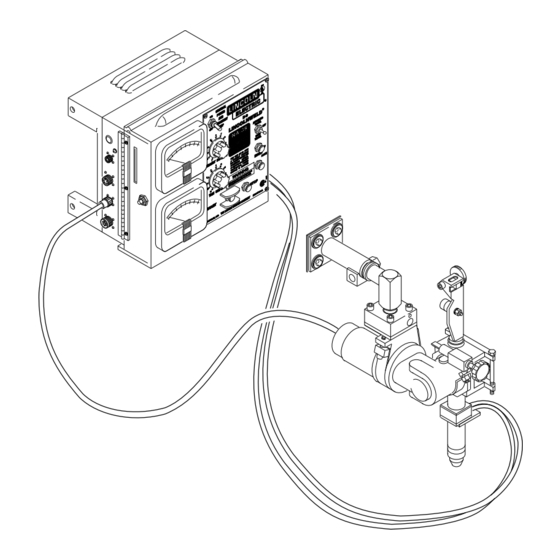
The NA-3 and NA-4 are fully automatic wire The NA-3 and NA-4 control units are supplied feed control units. The NA-3 can be used with with 115 VAC power usually from the welding either a constant current or a constant power source. -
Page 62: Control And Logic Boards
LOGIC SENSING SIGNALS BOARD START SWITCH STOP SWITCH 115 VAC INCH DOWN SWITCH VARIABLE VOLTAGE BOARD 115 VAC WIRE FEED POWER SOURCE ELECTRODE SPEED CONTROL OUTPUT CONTROL VOLTAGE SENSING VOLTAGE LEADS METER WORK 115 VAC 115 VAC NA-3 AND NA-4... -
Page 63: Variable Voltage Board
Arc voltage is monitored by the voltmeter The variable voltage board also generates a and variable voltage board. When the NA-3 low DC voltage that is applied to the and NA-4 are being operated in the constant electrode during the inch down mode. -
Page 64: Optional Start And Crater Fill Boards
1 CR SWITCH STOP 2 CR SWITCH 115 VAC INCH VARIABLE 3 CR DOWN VOLTAGE SWITCH 115 VAC BOARD WIRE FEED POWER SOURCE ELECTRODE VOLTAGE SPEED CONTROL OUTPUT CONTROL SENSING VOLTAGE LEADS METER WORK 115 VAC 115 VAC NA-3 AND NA-4... -
Page 65: Scr Operation
The amount of time spent in the on state is controlled by the gate. Since the wire speed of the NA-3 and NA-4 An SCR is fired by a short burst of current is controlled by silicon-controlled rectifier into the gate. - Page 66 F-23 Reed Switch (4CR) and Shunt Assembly Removal and Replacement (NA-3 Only) ......F-23 AC Current Transformer and Sensor PC Board Removal and Replacement (NA-4 Only) .
- Page 67 How To Use Troubleshooting Guide WARNING Service and Repair should only be performed by Lincoln Electric Factory Trained Personnel. Unauthorized repairs performed on this equipment may result in danger to the technician and machine operator and will invalidate your factory warranty. For your safety and to avoid Electrical Shock, please observe all safety notes and precautions detailed throughout this manual.
-
Page 68: Troubleshooting And Repair
“INSTALLED AND to prevent static buildup. Be sure not to SWITCHED PC BOARDS TO VERIFY touch any electrically live parts at the same PROBLEM”, will help avoid denial of time. legitimate PC board warranty claims. NA-3 AND NA-4... -
Page 69: Troubleshooting Guide
CAUTION If for any reason you do not understand the test procedures or are unable to perform the tests/repairs safely, contact the Lincoln Electric Service Department for technical troubleshooting assistance before you proceed. Call 216-383-2531 or 1-800-833-9353. NA-3 AND NA-4... -
Page 70: Troubleshooting Guide
CAUTION If for any reason you do not understand the test procedures or are unable to perform the tests/repairs safely, contact the Lincoln Electric Service Department for technical troubleshooting assistance before you proceed. Call 216-383-2531 or 1-800-833-9353. NA-3 AND NA-4... - Page 71 CAUTION If for any reason you do not understand the test procedures or are unable to perform the tests/repairs safely, contact the Lincoln Electric Service Department for technical troubleshooting assistance before you proceed. Call 216-383-2531 or 1-800-833-9353. NA-3 AND NA-4...
- Page 72 CAUTION If for any reason you do not understand the test procedures or are unable to perform the tests/repairs safely, contact the Lincoln Electric Service Department for technical troubleshooting assistance before you proceed. Call 216-383-2531 or 1-800-833-9353. NA-3 AND NA-4...
- Page 73 CAUTION If for any reason you do not understand the test procedures or are unable to perform the tests/repairs safely, contact the Lincoln Electric Service Department for technical troubleshooting assistance before you proceed. Call 216-383-2531 or 1-800-833-9353. NA-3 AND NA-4...
- Page 74 CAUTION If for any reason you do not understand the test procedures or are unable to perform the tests/repairs safely, contact the Lincoln Electric Service Department for technical troubleshooting assistance before you proceed. Call 216-383-2531 or 1-800-833-9353. NA-3 AND NA-4...
- Page 75 CAUTION If for any reason you do not understand the test procedures or are unable to perform the tests/repairs safely, contact the Lincoln Electric Service Department for technical troubleshooting assistance before you proceed. Call 216-383-2531 or 1-800-833-9353. NA-3 AND NA-4...
- Page 76 CAUTION If for any reason you do not understand the test procedures or are unable to perform the tests/repairs safely, contact the Lincoln Electric Service Department for technical troubleshooting assistance before you proceed. Call 216-383-2531 or 1-800-833-9353. NA-3 AND NA-4...
- Page 77 CAUTION If for any reason you do not understand the test procedures or are unable to perform the tests/repairs safely, contact the Lincoln Electric Service Department for technical troubleshooting assistance before you proceed. Call 216-383-2531 or 1-800-833-9353. NA-3 AND NA-4...
- Page 78 CAUTION If for any reason you do not understand the test procedures or are unable to perform the tests/repairs safely, contact the Lincoln Electric Service Department for technical troubleshooting assistance before you proceed. Call 216-383-2531 or 1-800-833-9353. NA-3 AND NA-4...
- Page 79 CAUTION If for any reason you do not understand the test procedures or are unable to perform the tests/repairs safely, contact the Lincoln Electric Service Department for technical troubleshooting assistance before you proceed. Call 216-383-2531 or 1-800-833-9353. NA-3 AND NA-4...
- Page 80 CAUTION If for any reason you do not understand the test procedures or are unable to perform the tests/repairs safely, contact the Lincoln Electric Service Department for technical troubleshooting assistance before you proceed. Call 216-383-2531 or 1-800-833-9353. NA-3 AND NA-4...
- Page 81 CAUTION If for any reason you do not understand the test procedures or are unable to perform the tests/repairs safely, contact the Lincoln Electric Service Department for technical troubleshooting assistance before you proceed. Call 216-383-2531 or 1-800-833-9353. NA-3 AND NA-4...
- Page 82 CAUTION If for any reason you do not understand the test procedures or are unable to perform the tests/repairs safely, contact the Lincoln Electric Service Department for technical troubleshooting assistance before you proceed. Call 216-383-2531 or 1-800-833-9353. NA-3 AND NA-4...
- Page 83 CAUTION If for any reason you do not understand the test procedures or are unable to perform the tests/repairs safely, contact the Lincoln Electric Service Department for technical troubleshooting assistance before you proceed. Call 216-383-2531 or 1-800-833-9353. NA-3 AND NA-4...
-
Page 84: Pc Board Led Definitions
LED LOCATIONS. LED LOCATIONS. LED 2C LED 1A LED 2A LED 2B NA-3/-4 LED 1B LED 2E LOGIC NA-3/-4 CONTROL LED 2D LED 2G LED 1D LED 1C LED 2H LED 2K LED 2J LED 2L LED 1E NA-3 AND NA-4... - Page 85 FIGURE F.4 – START/CRATER BOARD BOARD LED LOCATIONS. LED LOCATIONS. VARIABLE VOLTAGE LED 3A LED 4B LED 3B LED 4A Indicator Lights Conditions for Light “On” (NA-3 Set for CV) “Inch “Inch Up” Down” “Start” “Stop” Light Switch Switch Switch...
-
Page 86: Wire Feed Drive Motor Test
WIRE FEED DRIVE MOTOR TEST WARNING Service and repair should only be performed by Lincoln Electric factory trained personnel. Unauthorized repairs performed on this equipment may result in danger to the technician or machine operator and will invalidate your factory warranty. -
Page 87: Test Procedures
MOTOR APPLIED VOLTAGE TEST 1. Remove wire feed motor connector from the NA-3/NA-4 control 1. Carefully connect the isolated box. 120 VDC supply (SUPPLY TURNED OFF) to pins C and D on the motor 2. Using the ohmmeter, measure the connector. -
Page 88: Reed Switch (4Cr) And Shunt Assembly Removal And Replacement (Na-3 Only
REMOVAL AND REPLACEMENT (NA-3 ONLY) WARNING Service and repair should only be performed by Lincoln Electric factory trained personnel. Unauthorized repairs performed on this equipment may result in danger to the technician or machine operator and will invalidate your factory warranty. - Page 89 F-24 F-24 TROUBLESHOOTING AND REPAIR REED SWITCH (4CR) AND SHUNT ASSEMBLY REMOVAL AND REPLACEMENT (NA-3 ONLY) (continued) FIGURE F.6 – REED SWITCH REMOVAL. REED LOCK SHUNT SWITCH WASHER LEADS (525 COVER REED SWITCH 539S) REED SWITCH BRACKET LOCK SLOT WASHER...
- Page 90 REMOVAL AND REPLACEMENT (NA-3 ONLY) (continued) REMOVAL PROCEDURE mounting the reed switch to the reed switch bracket. 1. Remove input power to the NA-3 8. Carefully remove the reed switch. control box. 2. Using the 5/16 in. nutdriver, remove INSTALLATION PROCEDURE...
- Page 91 F-26 F-26 NOTES NA-3 AND NA-4...
-
Page 92: Ac Current Transformer And Sensor Pc Board Removal And Replacement (Na-4 Only
BOARD REMOVAL AND REPLACEMENT (NA-4 ONLY) WARNING Service and repair should only be performed by Lincoln Electric factory trained personnel. Unauthorized repairs performed on this equipment may result in danger to the technician or machine operator and will invalidate your factory warranty. - Page 93 FIGURE F.7 – AC CURRENT TRANSFORMER AND PC BOARD REMOVAL. CURRENT SENSOR COVER SHEET METAL SCREW CURRENT TRANSFORMER NA-4 CONTROL BOLT SCREW INSULATING SPACER WASHERS INSULATORS TERMINAL LEADS (539 & 528) CURRENT SENSOR GLASTIC COPPER PC BOARD LOCK SPACER CONDUCTER WASHER NA-3 AND NA-4...
- Page 94 PC board coil to the metal bracket screws using the 5/16 in. nutdriver. on the other glastic spacer. 7. Carefully remove the PC board; be careful when pulling leads #539 and #528 free from the grommet in the back of the control box. NA-3 AND NA-4...
-
Page 95: Wire Drive Motor Removal And Replacement
WIRE DRIVE MOTOR REMOVAL AND REPLACEMENT WARNING Service and repair should only be performed by Lincoln Electric factory trained personnel. Unauthorized repairs performed on this equipment may result in danger to the technician or machine operator and will invalidate your factory warranty. - Page 96 MOTOR REMOVAL PROCEDURE FIGURE F.8 – WIRE DRIVE MOTOR REMOVAL AND REPLACEMENT. 1. Remove the wire drive motor cable from the NA-3/NA-4 control box. 2. Using the 7/16 in. wrench, remove two 1/4-20 bolts holding the adapter DRIVE plate and motor assembly to the wire MOTOR feed gear box.
-
Page 97: Pc Board(S) Removal And Replacement
PC BOARD(S) REMOVAL AND REPLACEMENT WARNING Service and repair should only be performed by Lincoln Electric factory trained personnel. Unauthorized repairs performed on this equipment may result in danger to the technician or machine operator and will invalidate your factory warranty. - Page 98 4. Carefully remove the molex-type plugs connected to the PC board that is to be removed. 5. Using the Phillips head screwdriver, remove the PC board mounting PC BOARD screws. MOUNTING SCREWS 6. Carefully remove the PC board. NA-3 AND NA-4...
-
Page 99: Retest After Repair
Wire Feed Speed (per table - NA-3 CV only)... Wire Speed Range... - Page 100 Wiring Diagram (NA-3) ........
- Page 101 NOTES NA-3 AND NA-4...
- Page 102 ELECTRICAL DIAGRAMS Wiring Diagram (NA-3) NA-3N AND NA-3S WIRING DIAGRAM N.A. WHEN START P.C. BOARD IS INSTALLED, JUMPER CONNECTOR "A" IS REMOVED. N.G. WHEN CONTROLS ARE USED WITH R3S POWER SOURCES Methods of Travel Methods of Burnback OF THE TYPE WHICH USES TAPS CONNECTED WITH A N.B.
- Page 103 (Install jumper connector "B" Lead #694 to P8 from 584(c) to 583(c)) SWITCH #1 SWITCH #2 CURRENT TRANSFORMER 1-5-96J L6489 NOTE: This diagram is for reference only. It may not be accurate for all machines covered by this manual. NA-3 AND NA-4...
-
Page 104: Operating Schematic
ELECTRICAL DIAGRAMS Operating Schematic (NA-3) 510A SHUNT ELECTRODE LEAD TO POWER SOURCE 510A WORK LEAD TO WORK POWER SOURCE 510A LOGIC BOARD 510A 510A 525 (24V) VARIABLE VOLTAGE BOARD (NA-3S ONLY) D307 R306 D301 D306 N.F. C303 T301 D302 Q302... - Page 105 4.7K OHM 2 W R306 F103 3/10A FUSE X401 QUAD 2 INPUT NANDGATE R307 100 OHM T301 24V TRANSFORMER 1387 1-5-96J NOTE: This diagram is for reference only. It may not be accurate for all machines covered by this manual. NA-3 AND NA-4...
-
Page 106: Logic Pc Board (G1379-2 & Above) Schematic
NOTE: Lincoln Electric assumes no responsibility for liablilities resulting from board level troubleshooting. PC Board repairs will invalidate your factory warranty. Individual Printed Circuit Board Components are not available from Lincoln Electric. This information is provided for reference only. Lincoln Electric discourages board level troubleshooting and repair since it may compromise the quality of the design and may result NA-3 AND NA-4 in danger to the Machine Operator or Technician. -
Page 107: Electrical Diagrams
NOTE: Lincoln Electric assumes no responsibility for liablilities resulting from board level troubleshooting. PC Board repairs will invalidate your factory warranty. Individual Printed Circuit Board Components are not available from Lincoln Electric. This information is provided for reference only. Lincoln Electric discourages board level troubleshooting and repair since it may compromise the quality of the design and may result NA-3 AND NA-4 in danger to the Machine Operator or Technician. -
Page 108: Control Pc Board (L5224-5 & Above) Schematic
NOTE: Lincoln Electric assumes no responsibility for liablilities resulting from board level troubleshooting. PC Board repairs will invalidate your factory warranty. Individual Printed Circuit Board Components are not available from Lincoln Electric. This information is provided for reference only. Lincoln Electric discourages board level troubleshooting and repair since it may compromise the quality of the design and may result NA-3 AND NA-4 in danger to the Machine Operator or Technician. -
Page 109: Start Pc Board (L9917-1 & Above) Schematic
NOTE: Lincoln Electric assumes no responsibility for liablilities resulting from board level troubleshooting. PC Board repairs will invalidate your factory warranty. Individual Printed Circuit Board Components are not available from Lincoln Electric. This information is provided for reference only. Lincoln Electric discourages board level troubleshooting and repair since it may compromise the quality of the design and may result NA-3 AND NA-4 in danger to the Machine Operator or Technician. -
Page 110: Crater Fill Pc Board (L5222-2 & Above) Schematic
NOTE: Lincoln Electric assumes no responsibility for liablilities resulting from board level troubleshooting. PC Board repairs will invalidate your factory warranty. Individual Printed Circuit Board Components are not available from Lincoln Electric. This information is provided for reference only. Lincoln Electric discourages board level troubleshooting and repair since it may compromise the quality of the design and may result NA-3 AND NA-4 in danger to the Machine Operator or Technician.