Table of Contents
Advertisement
Advertisement
Table of Contents

Related Manuals for Panasonic KX-T0155


Summary of Contents for Panasonic KX-T0155
-
Page 1: Quick Installation Guide
Quick Installation Guide DECT 6.0 Cell Station Unit KX-T0155/ Model No. KX-T0158/KX-TDA0156 Thank you for purchasing a Panasonic DECT 6.0 Cell Station Unit. Please read this manual carefully before using this product and save this manual for future use. Document Version: 2009-12... -
Page 2: Important Information
Important Information Important Information SAVE THESE INSTRUCTIONS Safety Notices Please observe the safety notices in this manual in order to avoid danger to users or other people, and prevent damage to property. The notices are classified as follows, according to the severity of injury or damage: WARNING This notice means that misuse could result in death or serious injury. - Page 3 Important Information – Locations where air ventilation is poor. – Locations that may be exposed to sulphurous gas, such as near hot springs. – Near devices that emit heat, such as heaters. – Near devices that emit electromagnetic noise, such as radios or televisions. –...
-
Page 4: Additional Information
Important Information Additional Information F.C.C. REQUIREMENTS AND RELEVANT INFORMATION CAUTION Any changes or modifications not expressly approved by the party responsible for compliance could void the user's authority to operate this device. Note This equipment has been tested and found to comply with the limits for a Class B digital device, pursuant to Part 15 of the FCC Rules. - Page 5 Table of Contents Table of Contents 1 Overview ....................6 2 Procedure Overview ................10 3 Site Planning ..................12 4 Before Site Survey .................16 5 Site Survey ....................21 6 After Site Survey ..................25 7 Connecting a Cell Station to the PBX ..........26 8 Wall Mounting ..................42 9 Troubleshooting ..................45 Document Version 2009-12...
-
Page 6: Led Indications
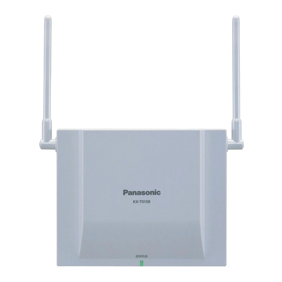
1 Overview 1 Overview Names and Locations KX-T0155/KX-TDA0156 Antennas CS ID Number (ID: xxxxxxxxxx) RJ11 Modular DIP Switch KX-T0158 Antennas CS ID Number (ID: xxxxxxxxxx) DIP Switch RJ45 Modular LED Indications Indication Color Description STATUS Green/Red CS status indication •... - Page 7 1 Overview Compatible PBX Cell Station Model No. MPR Software Version KX-T0155 KX-TAW848 PSMPR Software File Version 3.0000 or later KX-TDA50 KX-TDA100 PMPR Software File Version 3.0000 or later KX-TDA200 KX-TDA600 PLMPR Software File Version 3.1000 or later KX-TDE100 PMMPR Software File Version 1.0000 or later...
- Page 8 For more details about the Portable Station (PS), refer to the Operating Instructions of the PS. Maximum Number of CSs Supported by PBX Notice The CSs are for connection to specified Panasonic PBXs only. The following number of CSs can be supported by each PBX. Maximum Number...
- Page 9 1 Overview Equipment Distance CS and PS More than 1 m (3 ft 3 in) Each CS More than 3 m (10 ft) Each PS More than 0.5 m (1 ft 8 in) PBX and CS More than 2 m (6 ft 7 in) If multiple CSs cover the same area, the phone connection may become noisy or the number of possible simultaneous calls with PSs may decrease due to interference between the CSs.
-
Page 10: Procedure Overview
2 Procedure Overview 2 Procedure Overview When connecting the wireless system, use extreme care in conducting the site survey. An incorrectly performed site survey can result in poor service area, frequent noise, and disconnection of calls. Notice • When installing the DECT 6.0 wireless system in an area where another wireless system (2.4 GHz) is already installed, it is necessary to reconduct the site survey to find the optimum position for the CS. - Page 11 2 Procedure Overview Make sure that the radio signal strength level is greater than "3" at any location within the service area required by the user. 4. Finish the site survey Refer to "6 After Site Survey". Turn off the PS. Stop supplying power, and return all DIP switches of each CS to the OFF position.
-
Page 12: Site Planning
3 Site Planning 3 Site Planning Choosing the best site for the CS requires careful planning and testing of essential areas. The best location may not always be convenient for installation. Read the following information before installing the unit. Understanding Radio Waves Characteristics of Radio Waves The transmission of radio waves and the CS coverage area depend on the structure and materials of the building. - Page 13 3 Site Planning Object Material Transmission Tendency Wall Concrete The thicker they are, the less radio waves penetrate them. Ferroconcrete Radio waves can penetrate them, but the more iron there is, the more radio waves are reflected. Window Glass Radio waves usually penetrate them. Glass with wire net Radio waves can penetrate them, but tend to be reflected.
- Page 14 3 Site Planning CS Coverage Area The example below shows the size of the coverage area of 1 CS if it is installed in an area with no obstacles. Note Radio signal strength levels are measured during the site survey (refer to "5 Site Survey"). Coverage Area Radio signal strength level is greater than "3".
- Page 15 3 Site Planning If 1 CS cannot cover the entire service area, install additional CSs as required. Overlap the coverage areas of adjacent CSs. Where CS coverage areas overlap, the PS will start call handover to the next CS if the signal from one CS becomes weak.
-
Page 16: Before Site Survey
4 Before Site Survey 4 Before Site Survey Use the KX-TD7685/KX-TD7695/KX-TD7696 PS to conduct the site survey. Note Display prompts for the site survey are only available in English. Checking the CS ID Number Check the CS ID number label attached to the CS. If the CS ID number label is not attached to the CS, check the CS ID number using the Maintenance Console. - Page 17 Setting and Installing the CS Temporarily for Site Survey Switch the Radio Signal Test switch from OFF to ON. Set the channel number switches as desired. Set the Power Supply Select switch as desired. KX-T0155/KX-TDA0156 Channel 0 Channel 1 Channel 2...
- Page 18 4 Before Site Survey KX-T0158 Radio Signal Test Switch Power Supply Select Switch ON: From the AC Adaptor (KX-A11)/ Battery Box (PSZZTD142CE) OFF: From the PBX Channel Number Switch DIP Switch Channel 0 Channel 1 Channel 2 Channel 3 Channel 4 Note If more than 1 CS is in Radio Signal Test mode, each CS must have a unique channel number.
- Page 19 4 Before Site Survey KX-T0155/KX-TDA0156 KX-T0158 RJ11 Modular RJ45 Modular Telephone Cord Telephone Cord (PSJA1017Z) Power Supply Adaptor Power Supply Adaptor (PSZZ1TDA0142) (PSZZ1TDA0142) RJ11 Modular RJ11 Modular To AC Adaptor (KX-A11/KX-TCA1)/ To AC Adaptor (KX-A11)/ Battery Box (PSZZTD142CE) Battery Box (PSZZTD142CE)
- Page 20 4 Before Site Survey Install the CS temporarily for the site survey. Install the CS at least 2 m (6 ft 7 in) above the floor, and place the antennas so that they are pointing in directions that are 90 degrees apart (for antenna diversity), as follows: 45º...
-
Page 21: Site Survey
5 Site Survey 5 Site Survey The PS has a Radio Signal Test mode that monitors the state of the radio link to the CS for site survey. In Radio Signal Test mode, the frame loss and signal strength of a synchronous slot, and the signal strength of the other slots can be measured when the PS is monitoring the CS. - Page 22 5 Site Survey The above is a rough standard, and may vary depending on the environment. • When deciding where to install the CS, priority should be given to an error rate rather than a radio signal strength level. • After installing the CS according to the results of the survey, confirm that calls can be made and received, and conversations can be heard clearly.
- Page 23 5 Site Survey Repeat steps 1 and 2 for other CSs, and relocate the CSs when necessary. Plan adjacent CS coverage areas so that areas meet where radio signal strength level is "7" to "9". Channel no. 0 Channel no. 1 Plan the CS coverage areas to meet for at least 2 CSs at any location in the installation site.
- Page 24 If multiple CSs cover the same area, the phone connection may become noisy or the number of possible simultaneous calls with PSs may decrease due to interference between the CSs. As a guideline, the maximum number of CSs in an area with a radio signal strength of "11" is 4 (for KX-T0155)/2 (for the KX-T0158/KX-TDA0156).
-
Page 25: After Site Survey
Hold down the POWER button on the PS until the PS is turned OFF. Disconnect the CS from the AC adaptor/battery box or the PBX to stop supplying electricity. KX-T0155/KX-TDA0156 KX-T0158 Switch all DIP switches on the CS from ON to OFF. -
Page 26: Connecting A Cell Station To The Pbx
7 Connecting a Cell Station to the PBX 7 Connecting a Cell Station to the PBX Connection Examples for KX-TAW848/KX-TDA50 Refer to the following examples to connect a CS to the PBX. KX-T0155 connecting to KX-TAW848/KX-TDA50 Cable Maximum Distance 26 AWG:... - Page 27 7 Connecting a Cell Station to the PBX KX-T0158 connecting to KX-TDA50 Super Hybrid Port Cable Maximum Distance 26 AWG: 222 m (728 ft) 24 AWG: 347 m (1138 ft) 22 AWG: 500 m (1640 ft) CAT 5: 347 m (1138 ft) Port No.
- Page 28 7 Connecting a Cell Station to the PBX CS 1 (RJ45) DLC8 DLC8 card (RJ11) Port No. Signal Name Pin No. Port No. Signal Name Pin No. Master CS 2 (RJ45) Signal Name Pin No. Master Accessories and User-supplied Items for the CS Accessories (included): Screws ´...
- Page 29 KX-TDE200/KX-TDE600 Note for KX-TDE100/KX-TDE200 (PMMPR Software File Version 1.xxxx) Users When connecting both KX-T0155 and KX-T0158 CSs to the same card, the KX-T0158 CSs must be connected to lower-numbered pins on the card than the KX-T0155 CSs. Refer to the following examples to connect a CS to the PBX.
- Page 30 7 Connecting a Cell Station to the PBX KX-T0158 connecting to KX-TDA600/KX-TDE100/KX-TDE200/KX-TDE600 Note The illustration of the PBX is based on the KX-TDE200. DHLC8 Card Cable Maximum Distance 26 AWG: 222 m (728 ft) 24 AWG: 347 m (1138 ft) 22 AWG: 500 m (1640 ft) CAT 5:...
- Page 31 7 Connecting a Cell Station to the PBX Note • The no. 3, 4, 5 and 6 pins (Master) of the CS must be connected to 2 pairs of pins on the DHLC/ DLC card. • When connecting multiple KX-T0158 CSs to a DHLC/DLC card, make sure that the no. 3, 4, 5 and 6 pins (Master) of adjacent CSs are at least 2 pairs of pins away on the card.
- Page 32 7 Connecting a Cell Station to the PBX KX-TDA0156 connecting to KX-TDA100/KX-TDA200/KX-TDA600/KX-TDE100/KX-TDE200/ KX-TDE600 Note The illustration of the PBX is based on the KX-TDE200. CSIF8 Card Port 1 Cable Maximum Distance 26 AWG: 444 m (1457 ft) 24 AWG: 694 m (2277 ft) 22 AWG: 1000 m (3281 ft) CAT 5:...
- Page 33 7 Connecting a Cell Station to the PBX Connection Examples for KX-NCP500/KX-NCP1000 Refer to the following examples to connect a CS to the PBX. KX-T0155 connecting to KX-NCP500/KX-NCP1000 Note The illustration of the PBX is based on the KX-NCP500. DHLC4 Card...
- Page 34 7 Connecting a Cell Station to the PBX KX-T0158 connecting to KX-NCP500/KX-NCP1000 Note The illustration of the PBX is based on the KX-NCP500. DHLC4 Card Cable Maximum Distance 26 AWG: 222 m (728 ft) 24 AWG: 347 m (1138 ft) 22 AWG: 500 m (1640 ft) CAT 5:...
- Page 35 7 Connecting a Cell Station to the PBX DLC8/DLC16 card (RJ45) Pin No. Signal Name Port No. DLC8 Port No.: 1 2 3 4 5 6 7 8 10 11 12 13 14 15 16 DLC16 CS 1 (RJ45) Signal Name Pin No.
- Page 36 7 Connecting a Cell Station to the PBX Accessories and User-supplied Items for the CS Accessories (included): Screws ´ 2, Washers ´ 2 User-supplied (not included): RJ45 connector Note • The no. 3, 4, 5 and 6 pins (Master) of the CS must be connected to 2 pairs of pins on the DHLC/ DLC card.
- Page 37 7 Connecting a Cell Station to the PBX Connecting the CS Connect the cable from the PBX to the CS. KX-T0155/KX-TDA0156 KX-T0158 RJ11 Modular RJ45 Modular To PBX To PBX Pass the cable through the groove of the CS (in any direction depending on your preference).
- Page 38 7 Connecting a Cell Station to the PBX Note means default value throughout this section. Setting the Personal Identification Number (PIN) for PS Registration To prevent registering the PS to a wrong PBX, a PIN for PS registration can be set to the PBX. Before registering the PS to the PBX, enter the PIN set to the PBX into the PS.
- Page 39 7 Connecting a Cell Station to the PBX Using the KX-TD7685/KX-TD7695/KX-TD7696 If required C.Tone C.Tone Press Press "F" Select the desired POWER for for 2 language. seconds. 2 seconds. When the PS has already been registered to another PBX One PS can be registered to a maximum of 4 different PBXs. Using the KX-TD7685/KX-TD7695/KX-TD7696 Press Select...
- Page 40 7 Connecting a Cell Station to the PBX Using the KX-TD7685/KX-TD7695/KX-TD7696 Press Select Select POWER for "Setting Handset". "System Option". 2 seconds. If required System Lock Password 4 digits Select Choose "On/Off". "System Lock". System Lock Password System Lock Password 4 digits 4 digits C.Tone...
- Page 41 7 Connecting a Cell Station to the PBX Using the KX-TD7685/KX-TD7695/KX-TD7696 Press POWER Select Select for 2 seconds. "Setting Handset". "System Option". If required System Lock Password 4 digits Select Select the desired "Cancel Base". base (Base 1–4). C.Tone Select "Yes". Testing the Operation Walk around the service area while having a conversation using a registered PS.
-
Page 42: Wall Mounting
8 Wall Mounting 8 Wall Mounting Mounting the KX-T0155/KX-T0158/KX-TDA0156 WARNING • Make sure that the wall that the unit will be attached to is strong enough to support the unit (approx. 310 g [11 oz]). If not, it is necessary for the wall to be reinforced. - Page 43 8 Wall Mounting Slide the wall mounting plate in the direction of the arrow until it clicks. KX-T0155/KX-TDA0156 KX-T0158 Hook the CS on the screw heads. KX-T0155/KX-TDA0156 KX-T0158 Washer Washer Drive the screw Drive the screw to this point. to this point.
- Page 44 8 Wall Mounting Reference for Wall Mounting Please copy this page and use as a reference for wall mounting. Install a screw here. 83 mm (3-1/4 in) 100 mm (3-15/16 in) Install a screw here. Note Make sure to set the print size to correspond with the size of this page. If the dimension of the paper output still deviates slightly from the measurement indicated here, use the measurement indicated here.
-
Page 45: Troubleshooting
KX-T0155 CSs. card, and the KX-T0158 • Connect the KX-T0158 and KX-T0155 CSs are connected to CSs to different cards. higher-numbered pins on the card than the KX-T0155 CSs. - Page 46 9 Troubleshooting PROBLEM PROBABLE CAUSE SOLUTION • • • Cannot register the PS. Wrong Personal Enter the PIN set to the PBX into the Identification Number (PIN) is registered to the PS. • • • PS becomes out of range. Location of CS is not good.
- Page 47 Notes Document Version 2009-12 Quick Installation Guide...
- Page 48 Copyright: This material is copyrighted by Panasonic System Networks Co., Ltd., and may be reproduced for internal use only. All other reproduction, in whole or in part, is prohibited without the written consent of Panasonic System Networks Co., Ltd. © Panasonic System Networks Co., Ltd. 2009 PSQX4669WA KK0208EK3129 (v0.004)