Table of Contents
Advertisement
Quick Links
AMERICAN-LINCOLN
TECHNOLOGY
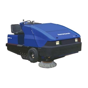
MPV-60
OPERATOR'S
POWER
MANUAL &
SWEEPER
PARTS LIST
Beginning with Serial No. 482001
READ THIS BOOK
This book has important information for the use and safe operation of this machine. Failure
to read this book prior to operating or attempting any service or maintenance procedure to
your machine could result in injury to you or to other personnel; damage to the machine or to
other property could occur as well. you must have training in the operation of this machine
before using it. If you or your operator (s) cannot read English, have this manual explained
fully before attempting to operate this machine.
ISO 9001
U L
Si Ud. o sis operadores no pueden leer el Inglés, se hagen explicar este manual completamente
®
antes de tratar el manejo o servicio de esta máquina.
#
FILE A2287
All directions given in this book are as seen from the operator's position at the rear of the machine.
For new books, write to: American-Lincoln, Inc., 1100 Haskins Road, Bowling Green, Ohio 43402
American-Lincoln®
USA
Part No. 2-86-00398
2004
Printed in the
Advertisement
Table of Contents

Related Manuals for Alto MPV-60


Summary of Contents for Alto MPV-60
- Page 1 AMERICAN-LINCOLN TECHNOLOGY MPV-60 OPERATOR'S POWER MANUAL & SWEEPER PARTS LIST Beginning with Serial No. 482001 READ THIS BOOK This book has important information for the use and safe operation of this machine. Failure to read this book prior to operating or attempting any service or maintenance procedure to your machine could result in injury to you or to other personnel;...
-
Page 2: Table Of Contents
TABLE OF CONTENTS MACHINE SPECIFICATIONS ..............................1-4 MACHINE DIMENSIONS ................................1-6 MACHINE PREPARATION ............................... 1-7 SAFETY PRECAUTIONS ................................. 1-8 SWEEPER CONTROLS/INSTRUMENTS ..........................1-10 HORN BUTTON ................................. 1-10 LIGHT SWITCH .................................. 1-10 GLOW PLUG SWITCH ..............................1-10 CHECK ENGINE LIGHT ..............................1-10 KEY SWITCH .................................. - Page 3 TABLE OF CONTENTS TO CHANGE THE SIDE BROOM ............................1-32 HOPPER .................................... 1-33 TO CLEAN HOPPER ................................1-33 TO CHECK HOPPER SEALS ............................. 1-33 TO CHECK HOPPER FLAPS .............................. 1-33 DUST FLAPS ..................................1-33 TO CHECK THE DUST FLAPS ............................1-33 TO ADJUST THE DUST FLAPS ............................
- Page 4 TABLE OF CONTENTS BATTERY2-39 HYDRAULIC RESERVOIR ................................. 2-40 VACUUM FAN ................................... 2-42 FLAPS (WHEEL WELL) ................................2-44 BROOM CHAMBER FLAPS AND SEALS ..........................2-46 CONTROL AND RELIEF VALVE ..............................2-48 PUMP ....................................2-50 HYDRAULIC FILTER .................................. 2-52 INSTRUMENT PANEL ................................. 2-53 INSTRUMENT HOUSING ................................
-
Page 5: Specifications
SPECIFICATIONS TRAVEL SPEED 0 - 8 MPH (0 - 12.875 kph) TURNING RADIUS Left 67” (170 cm) Right 91.5” (232 cm) DIMENSIONS Length 98” (249 cm) Width 62” (157 cm) Height 50.75” (129 cm) Height W/Overhead Guard 78” (198 cm) Wheel Base 43”... -
Page 6: Side Broom Spotlight
SPECIFICATIONS HOPPER Sweep Opening 43” (109 cm) Volumetric Capacity 14 cubic feet Weight Capacity 1200 lb. (447.6 kg) Floor Length 34.25” (87 cm) Ground Clearance 5.5” (14 cm) FILTRATION SYSTEM Air passes through water resistant panel filter that controls dust to one (1) micron in size Filtering Area 88 square feet (8.18 m2) HYDRAULIC SYSTEM... -
Page 7: Machine Dimensions
MACHINE DIMENSIONS 78.00 " 198 cm 50.75 " 129 cm American-Lincoln 62.00 " 157 cm 96.00 " 235 cm 60.00 " 147 cm 98 " 249 cm C0495ecp/1203 American-Lincoln MPV 60... -
Page 8: Machine Preparation
START C1432/9810 C-1432 FIGURE 1 YOUR MPV-60 SWEEPER HAS BEEN SHIPPED COMPLETE, BUT DO NOT ATTEMPT TO OPERATE WITH- OUT READING AND FOLLOWING THESE INSTRUCTIONS. PREPARATION 1. Uncrate the sweeper and carefully remove packing material. 2. Inspect the battery connections. -
Page 9: Safety Precautions
SAFETY PRECAUTIONS THE FOLLOWING STATEMENTS ARE USED THROUGHOUT THIS MANUAL AS INDICATED IN THEIR DESCRIPTIONS: DANGER To warn of immediate hazards which will result in severe personal injury or death. WARNING To warn of hazards or unsafe practices which could result in severe personal injury or death. CAUTION To warn of hazards or unsafe practices which could result in minor personal injury. - Page 10 SAFETY PRECAUTIONS WARNING Be careful when operating the machine on a ramp or incline. Always move slowly on a ramp. Do not turn this machine on a ramp. Do not stop and leave this machine on a ramp. WARNING Stop and leave this machine on a level surface. When stopping the machine, put the power switch in the “OFF”...
-
Page 11: Sweeper Controls/Instruments
SWEEPER CONTROLS/INSTRUMENTS GLOW PLUG HOUR METER SWITCH MAIN WARNING BANK BROOM LEVER FUEL GAUGE FILTER SHAKER SWITCH LIGHT DUST CONTROL SWITCH SWITCH SIDE BROOM HOPPER LEVER LEVER ENGINE SPEED HOPPER SWITCH (Gas/LP) DOOR LEVER SWITCH BROOM SIDE LEVER BROOM ADJUSTMENT CHECK ENGINE TILT... -
Page 12: Key Switch
SWEEPER CONTROLS/INSTRUMENTS KEY SWITCH (figure 3) The keyed ignition switch is located on the instrument panel to the right of the steering column. The key switch is a four position switch that controls power to the sweeper systems and accessories. The “OFF ” position (0 position) will shut off the engine. -
Page 13: Foot Brake
SWEEPER CONTROLS/INSTRUMENTS FOOT BRAKE (figure 6) The foot brake pedal is located on the floor of the operator’s compartment to the left of the foot pedal. To stop, use the sweepers front wheel brakes, by putting pressure on the brake pedal. PARKING BRAKE (figure 7) The parking brake lever is located on the operator’s compartment left side panel near the floor. -
Page 14: Warning Bank
SWEEPER CONTROLS/INSTRUMENTS HOPPER WARNING ENGINE DUMP DOOR BANK TEMP LIGHT LIGHT DUST ENGINE OIL CONTROL PRESSURE LIGHT LIGHT HOPPER TEMP CHARGING LIGHT SYSTEM LIGHT C1422 C-1422 FIGURE 9 WARNING BANK The Warning Bank is located on the instrument panel and provides the operator with six fault/status indicators for engine and sweeper systems. -
Page 15: Tilt Steering Lever
SWEEPER CONTROLS/INSTRUMENTS TILT STEERING LEVER (figure 10) TILT STEERING The tilt steering lever is located near the base of the steering LEVER column and is spring loaded to the locked position. To adjust the steering column tilt angle, Grasp the lever and TILT LOCK pull back. -
Page 16: Dust Control Switch
SWEEPER CONTROLS/INSTRUMENTS DUST CONTROL SWITCH (figure 13) DUST CONTROL The dust control is a two position switch that is located on the instrument panel next to the engine speed switch. The switch controls the vacuum fan in the dust control system. To turn on the dust control system for “NORMAL”... -
Page 17: Side Broom Lever
SWEEPER CONTROLS/INSTRUMENTS SIDE BROOM LEVER (figure 16) The side broom lever is located on the right side of the instrument panel. The side broom lever raises and lowers the side broom. Use the brooms lever on the operator’s center console to turn on the side broom. SIDE BROOM LEVER To raise the side broom, pull the lever back into the “UP”... -
Page 18: Hopper Door Lever
SWEEPER CONTROLS/INSTRUMENTS HOPPER DOOR LEVER (figure 18) The hopper door lever is located on the operator’s compart- HOPPER DOOR ment center console and is used to close and open the LEVER hopper dump door. The lever is a three position hydraulic valve that is spring loaded to the center position which “HOLDS”... -
Page 19: Circuit Breakers
SWEEPER CONTROLS/INSTRUMENTS CIRCUIT BREAKERS (figure 22) The circuit breakers are located to the left of the steering CIRCUIT wheel. When a circuit breaker “pops” out, this is an BREAKERS indication of an electrical problem that must be corrected before the breaker can be reset. There can be up to eight circuit breakers in the row. -
Page 20: Hydraulic Reservoir Lever Sight Gauge
SWEEPER CONTROLS/INSTRUMENTS HYDRAULIC RESERVOIR LEVEL SIGHT GAUGE (figure 24) The sight gauge is located on the side of the hydraulic reservoir in the engine compartment. The sight gauge is used to indicate the level of fluid in the reservoir. Fluid level HYDRAULIC RESERVOIR must be visible in the sight gauge when the hopper is in the LEVEL SIGHT GAUGE... -
Page 21: Hopper Cover Latch
SWEEPER CONTROLS/INSTRUMENTS HOPPER COVER LATCH (figure 26) The hopper has two hinged covers for easy access to the hopper components may be needed for inspection or PRESS LIFT AND TURN service. To access the upper hopper cover (single latch at top) 1. -
Page 22: Hopper Temp Sensor
SWEEPER CONTROLS/INSTRUMENTS HOPPER TEMP SENSOR (OPTION) (figure 29) The hopper temp sensor thermal switch can be reset, which is located in the hopper filter compartment near the RESET HOPPER vacuum fan intake. BUTTON TEMP SENSOR The temp sensor switch monitors the hopper air tempera- PUSH TO RESET ture near the vac fan. -
Page 23: Helpful Hints For Sweeping
HELPFUL HINTS FOR SWEEPING SIDE AISLES MAIN AISLE SIDE AISLES P4134/0001 P-4134 FIGURE 31 WARNING Do Not Turn The Steering Wheel Sharply When The Machine Is In Motion. The Sweeper Is Very Responsive To Movement Of The Steering Wheel. Do Not Make Sudden Turns. Pick up large debris before sweeping with machine. -
Page 24: Operating Instructions
OPERATING INSTRUCTIONS C0520 C-0520 FIGURE 32 NOTE When Machine Has Been Stored In Below Freezing Temperatures, Run Engine At The “1” (low) Speed Setting With Machine Standing Still For 5 To 10 Minutes To Warm Engine And Hydraulic Oil. TO START GAS ENGINE 1. -
Page 25: To Drive Sweeper For Transport
OPERATING INSTRUCTIONS 1. Perform the Pre-Start checks found previously in this manual. 2. Turn the ignition switch to the “ON” position and place the engine speed switch to the high speed (2) position. 3. Push and hold the glow plug switch for approximately 30 seconds. Under cold starting conditions, the glow plug switch may be held longer but do not hold the switch for more than 60 seconds to prevent damage to the glow plugs. -
Page 26: To Empty Debris Hopper
OPERATING INSTRUCTIONS TO EMPTY DEBRIS HOPPER 1. Press the engine speed switch to the “1” (Normal) or ”2" (High) position. 2. Engage parking brake. 3. Move the Hopper Dump door lever to the “CLOSE” Position until door is closed. 4. Move the hopper lift lever to the “RAISE” position until the hopper reaches the desired height. 5. - Page 27 MAINTENANCE PULSE AIR SYSTEM - OPTION The most important step to insure proper operation of the Pulse Air System is keeping the clean side of the filter clean. Dirt inside the compressor reservoir system can lead to air leaks. Air leaks will prevent the system from reaching the trigger pressure and then the system will stop working properly.
- Page 28 PULSE AIR SYSTEM - OPTION FILTER HOLD DOWN SOLENOID VALVES DIAPHRAGM VALVE COMPRESSOR FILTER C0810/9801 DISCHARGE RESERVOIR American-Lincoln 1-27 MPV 60...
-
Page 29: Service Precautions
SERVICE PRECAUTIONS WARNING Do not attempt to Service this Machine until you have read and understand all Safety Warnings associated with the equipment you are working on. WARNING Electrical repairs must be done by authorized personnel only. Consult your American-Lincoln Authorized Service Person to do service procedures. -
Page 30: Service Chart
SERVICE CHART EVERY 8 HOURS or DAILY operation check and clean/adjust if necessary: 1. Inspect panel filter for damage and clean. 2. Check engine oil level 3. Check hydraulic fluid level 4. Check radiator cooling fins for blockage 5. Check all flaps for wear or damage 6. - Page 31 SERVICE CHART 1,17 36,37,38 8,29 18,28, 10,30 35,39 14,27 9,34 5,6,16 24,26 C-0549-1/9702 1-30 American-Lincoln MPV 60...
-
Page 32: Service Instructions
SERVICE INSTRUCTIONS SWEEPING SYSTEM SERVICE MAIN BROOM To prevent the broom from “setting” in one direction and to provide the maximum life of the broom it is recom- mended that the broom be turned end for end periodically. TO CHECK THE MAIN BROOM SWEEP PATTERN Check the main broom sweep pattern after changing the broom or when poor sweeping performance is encoun- tered while sweeping. -
Page 33: Side Broom
SERVICE INSTRUCTIONS SIDE BROOMS SERVICE FLOOR LOCK PIN CONTACT AREA FORWARD SIDE BROOM C-0541 C-0541 FIGURE 33 SIDE BROOM The Side Broom sweeping angle is not adjustable however the height of the side brooms can be adjusted to compensate for wear as the broom becomes worn from use. Always check and adjust the sweep pattern after changing the side broom. -
Page 34: Hopper
SERVICE INSTRUCTIONS HOPPER SERVICE DUST CONTROL FILTER VIBRATION HOPPER SEALS HOPPER FLAPS C-0551A/0703 C-0551A FIGURE 34 HOPPER The hopper houses the debris compartment, the dust control filter and the vibrating arm. For maximum perfor- mance and service life, keep the hopper clean and inspect the seals and flaps daily. Clean the hopper prior to parking the sweeper at the end of the day. -
Page 35: Dust Control Filter
SERVICE INSTRUCTIONS HOPPER SERVICE-Cont. DUST CONTROL FILTER The dust control filter should be checked daily for damage and cleaned if necessary. A damaged filter must be replaced to prevent damage to other dust control system components. Inspect the filter for tears in the filter media or excessive dirt lodged in the pleats. -
Page 36: Brake Service
SERVICE INSTRUCTIONS BRAKE SERVICE TENSION KNOB CLEVIS PIN PARKING PULL ROD BRAKE BRAKE CROSS SHAFT BRAKE BRAKE PEDAL LEVER SPRING AXLE NUT C-0550 C0550 FIGURE 35 BRAKES The service brakes are located on the front wheels. They are operated by the brake pedal and the parking brake lever. -
Page 37: Hydraulic System Service
SERVICE INSTRUCTIONS HYDRAULIC SYSTEM SERVICE RETURN FILTER RESERVOIR FILL CAP PRESS. GAUGE HYDRAULIC OIL COOLER HYDRAULIC RESERVOIR HYDRAULIC SUCTION STRAINER C0547 C-O547 FIGURE 36 HYDRAULIC SYSTEM The brooms, hopper lift , hopper door, drive motor and vacuum fan are hydraulic powered. It is very important to prevent contamination in the hydraulic system. -
Page 38: To Clean The Hydraulic Suction Strainer
SERVICE INSTRUCTIONS HYDRAULIC SYSTEM SERVICE-Cont. TO CLEAN THE HYDRAULIC SUCTION STRAINER Remove the hydraulic suction strainer after draining the hydraulic reservoir. The suction strainer is part of the filter assembly located on the side of the hydraulic reservoir. It can be removed from the reservoir for replace- ment. -
Page 39: Air Filter
SERVICE INSTRUCTIONS AIR INTAKE SYSTEM NOTE Monitor the air filter indicator daily The importance of replacing the air filter at the appropriate time cannot be overemphasized. Even a small amount of dirt ingested through the air intake system will wear out a set of piston rings in just a few hours. Always cover the air intake when removing the air filter for replacement. -
Page 40: Engine Cooling System Service
SERVICE INSTRUCTIONS ENGINE COOLING SYSTEM SERVICE HOSES Check all hoses and connections for leaks. Replace any of the hoses are cracked, frayed, or feel spongy. RADIATOR Inspect the exterior of the radiator daily for obstructions. Remove all bugs, dirt, or foreign material with a soft brush or cloth. -
Page 41: Lp Safety Precautions
LP SAFETY PRECAUTIONS WARNING Keep cigarettes, sparks, and open flame away when working on LP equipment. When inspecting for gas leaks or when LP tanks are present. WARNING Check all components for proper operation. Replace LP components when needed. Never by-pass defective safety components. -
Page 42: Lp Components
LP COMPONENTS LP FUEL SYSTEM The LP fuel system consists of several components not found on the gasoline system. The LP fuel system also contains the associated mounting hardware and plumbing for the LP components. The major LP components are as follows (these components are factory set, adjustments to these components should only be made by autho- rized service personnel): 1. -
Page 43: Lp Fuel Tanks
LP COMPONENTS LP FUEL TANKS Standard D.O.T. LP fuel tank sizes have 14, 20, 33.5, and 43.5 pounds capacities. The liquid volume permitted in these containers is less than the total volume of the cylinder. This provides for expansion of the LP fuel should be temperature increase above the normal amounts. -
Page 44: Storage Of Lp Fuel Tanks
LP TANK CARE TO BEGIN CHANGING THE LP TANK Park the machine in a designated safe area and set the parking brake. Close the tank valve. Remove the quick-disconnect coupling from the tank valve. Inspect the machine’s fuel lines and the quick disconnect coupling for damage or abnormal wear. Remove the empty tank from the holding device. - Page 45 TORQUE REQUIREMENTS STANDARD METRIC TORQUE VALUES When tightening torques are not specified, tighten the bolts and nuts according to the table below. GRADE No-Grade or 4T SS41, S20C S43C, S48C SCR435, SCM435 Nom. Unit kgf.m ft-lbs kgf.m ft-lbs kgf.m ft-lbs Dia.
-
Page 46: Hydraulic Torque Requirements
HYDRAULIC TORQUE REQUIREMENTS HYDRAULIC TORQUE REQUIREMENTS Refer to the following chart for torque values on all hydraulic hoses and fittings. Nominal O-Ring Face Seal End SAE O-Ring Boss End Thread Swivel Thread Str. Fitting Dash Size Size or Locknut Size Inch Torque Inch... - Page 47 STANDARD HARDWARE & TORQUE REQUIREMENTS SAE - Grade 8 SAE - Grade 5 Type Grade Screw Grade Type Brass 410H F & T Size B, AB Stainless & BT Plated Plated *1/4 5/16 7/16 9/16 C = Coarse Thread F = Fine Thread * = Torque values for #6 through 1/4 are lb./in.
-
Page 48: Decimal-Metric Conversion Table
DECIMAL METRIC CONVERSION TABLE DECIMAL DECIMAL FRACTION MILLIMETER FRACTION MILLIMETER C-2001/9907 American-Lincoln 1-47 MPV 60... -
Page 49: Hardware Abbreviations
HARDWARE ABBREVIATIONS ABBREVIATIONS - SCREWS = Adjusting Screw = Adjusting Plunger Screw ADJ.SP = Binding Head Machine Screw = Button Head Socket Screw = Captivated Slotted Screw CAPT.SL = Captivated Wing Screw CAPT.WG = Flat Head Machine Screw = Filister Head Machine Screw FIL.HM = Hexagon Head Cap Screw = Hexagon Head Machine Screw... -
Page 50: Hardware Legend
HARDWARE LEGEND Key No. Part Number Description 2-00-05060 Screw, #6-32 x 1.250 RHM 2-00-00455 Flat Washer, .375 x .156 x .047 2-00-01499 Lock Washer, #6 Med. Helical Spring 2-00-00624 Nut, #6-32 Hex 2-00-00645 Nut, Hex Fiber Insert #6-32 2-00-00049 Screw, # 10-24 x .500 RHM 2-00-00056 Screw, # 10-24 x .750 RHM 2-00-00039... - Page 51 HARDWARE LEGEND Key No. Part Number Description 2-00-00239 Screw, 1/2-13 x 1.000 HHC 2-00-00240 Screw, 1/2-13 x 1.250 HHC 2-00-00241 Screw, 1/2-13 x 1.750 HHC 2-00-00242 Screw, 1/2-13 x 2.250 HHC 2-00-02682 Screw, 1/2-13 x 2.750 HHC 2-00-02616 Screw, 1/2-13 x 3.000 HHC 2-00-00405 Flat Washer, 1.063 x .531 x .094 2-00-02312...
- Page 52 HARDWARE LEGEND Key No. Part Number Description H112 2-00-02603 Screw, 3/8-16 x 3.500 HHC H113 2-00-03333 Screw, 3/8-16 x 3.750 HHC H114 2-00-00633 Nut, Fiber 1/4-28 H115 2-00-03063 Screw, #10-24 x .750 THM H116 2-00-01951 Carriage Bolt, 1/4-20 x 1.250 H117 2-00-05067 Flat Washer, 1.750 x .531 x .100...
- Page 53 HARDWARE LEGEND Key No. Part Number Description H168 2-00-05261 Insert, 1/4-20 H169 2-00-02637 Screw, 1/4-20 x 2.750 HHC H170 2-00-03061 Screw, # 10-24 x .500 THM H171 2-00-02371 Nut, Hex Jam .50-13 STL. H172 2-00-04986 Screw, 1/4-20 x 4.500 H173 2-00-02709 Screw, 5/16-18 x 1.500 H174...
- Page 54 HARDWARE LEGEND Key No. Part Number Description H224 2-00-04686 Lock Washer-helical#10Scr.Med. SS H225 2-00-04851 Washer, Engine Mount H226 2-00-04689 Washer, 11/16 OD x .260 ID x .050 H227 2-00-04596 Screw, Hex Head 1/4 - 20 x 3.5 H228 2-00-02606 Screw, .375 - 24 x 1.00, STL HHC H229 2-00-01490 Screw, .25 - 20 x .875 HHC STL...
- Page 55 HARDWARE LEGEND Key No. Part Number Description H280 2-00-00187 Bolt Carriage, .38 - 16 x 2.50 H281 2-00-00415 Flat Washer, .9375 x .468 x .0625SS H282 2-00-02562 Fitting H283 2-00-03842 Roll Pin, 1/4 x 1.00 H284 2-00-04845 Screw, 3/8-16 x 1.00 FHSC H285 2-00-05153 Screw, 1/4 x 20 1.50 HHC...
-
Page 56: Check Engine Light Codes
CHECK ENGINE LIGHT CODES CATEGORY DESCRIPTION CODE NUMBER MAP high pressure MAP low voltage TIP high voltage 1111 TIP low voltage 1111 FP high voltage 1111 FP low voltage 1111 ECT/CHT ECT/CHT high voltage ECT/CHT low voltage ECT higher than expected 1 ECT higher than expected 2 CHT higher than expected 1 CHT higher than expected 2... - Page 57 CHECK ENGINE LIGHT CODES CATEGORY DESCRIPTION DESCRIPTION CODE NUMBER Auxiliary Analog Inputs AUX analog PD1 high AUX analog PD1 low AUX analog PU1 high AUX analog PU1 low AUX analog PU2 high AUX analog PU2 low Engine Speed Max govern speed override Fuel rev limit Spark rev limit Oil Pressure...
- Page 58 CHECK ENGINE LIGHT CODES CATEGORY DESCRIPTION DESCRIPTION CODE NUMBER Spark Coil Primary Primary Loop Open or Coil 1 Low-Side Short to Ground Coil 2 Coil 3 Coil 4 Primary Coil Shorted Coil 1 Coil 2 Coil 3 Coil 4 Fuel Pump Feedback F Pump Loop Open or High-Side Short to Ground F Pump High-Side...
-
Page 59: Ordering Parts
Fax: +1 416 6 75 69 89 E-mail: info@alto-nl.com Tel.: +1 704 971 1240 Fax: +1 704 971 1241 CROATIA NORWAY E-mail: info@altocsi.com Wap ALTO Strojevi za ciscenje, d.o.o. ALTO Norge A/S Siget 18a Bjørnerudveien 24 10020 Zagreb 1266 Oslo Tel.: +385 1 65 54 144 Tel.: +47 22 75 17 70...