BBV TX1500 system Installation Manual
Video switching matrix 3-axis joystick keyboard 16 input alarm card rs232/422/485 interface
Hide thumbs
Also See for TX1500 system:
- Installation manual (32 pages) ,
- Installation manual (31 pages)
Table of Contents
Advertisement
Installation
Guide
TX1500 system
TX1500 Matrix
TX1500/KBD
TX1500/AL16
TX1500/BBUS-IF
Building Block Video Ltd.,
17 Apex Park
Diplocks Industrial Estate,
Hailsham, East Sussex, BN27 3JU UK.
Tel: +44 (0)1323 842727
Fax: +44 (0)1323 842728
Support: +44(0)1323 444600
Web Site: http://www.bbvcctv.com
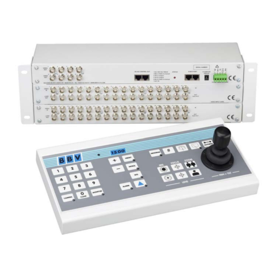
Video switching matrix
3-axis joystick keyboard
16 input alarm card
RS232/422/485 interface
BBV
Advertisement
Table of Contents

Related Manuals for BBV TX1500 system


Summary of Contents for BBV TX1500 system
-
Page 1: Installation Guide
Installation Guide TX1500 system TX1500 Matrix Video switching matrix TX1500/KBD 3-axis joystick keyboard TX1500/AL16 16 input alarm card TX1500/BBUS-IF RS232/422/485 interface Building Block Video Ltd., 17 Apex Park Diplocks Industrial Estate, Hailsham, East Sussex, BN27 3JU UK. Tel: +44 (0)1323 842727... -
Page 2: Table Of Contents
Contents Unpacking Safety Precautions System Components Description TX1500 components Product Codes TX1500 System Example BBUS control bus BBUS example wiring RS485 Telemetry port RS485 wiring diagrams 8, 9 Video Input Card Monitor Output Card Matrix ALARM 00 & relay connector... -
Page 3: Unpacking
UNPACKING Inspect the packaging for signs of damage. If damage has occurred, advise the carriers and/or the suppliers immediately. Unpack the units carefully and check that all the items are present and correct. SAFETY PRECAUTIONS All normal safety precautions as laid down by British Standards and the Health and Safety at Work Act (or the relevant National safety legislation if installing in a country outside the U.K.) should be observed, and servicing should be referred to qualified service personnel. -
Page 4: Description
Eight monitor outputs are provided with monitors 1,2,3 & 4 having on screen display. BBV & VISTA up-the-coax and BBV 485 & VISTA 485 linked receivers and domes can be controlled when viewed on any monitor. Pelco and VCL up-the-coax control is limited to monitors 1-4. -
Page 5: Tx1500 System Example
Rx100 Rx400P Rx300 Rx400DC Rx45X Rx55X Rx200 + dome camera + preset pan/tilt camera + pan/tilt camera + DC preset pan/tilt + panning camera Multi-protocol Multi-protocol camera + AC Preset pan/tilt + DC preset pan/tilt STATIC camera camera video in - coax RS485 StarCard 8 outputs TX1500/16/8/16AL Matrix twin STP... -
Page 6: Bbus Control Bus
BBUS CONTROL BUS The TX1500 communicates with all keyboards, alarm cards and BBUS-IF interfaces via a polled 4 wire multidrop RS422 control bus named BBUS. All the units are equipped with standard RJ45 connectors allowing cat 5 patch cables to be used to connect over short distances. -
Page 7: Bbus Example Wiring
SYSTEM BBUS WIRING EXAMPLES The following diagrams show examples of various wiring schemes. BBUS maximum distance 1200M 1 2 3 4 5 6 7 8 1 2 3 4 5 6 7 8 1 2 3 4 5 6 7 8 1 2 3 4 5 6 7 8 1 2 3 4 5 6 7 8 Matrix SW2... -
Page 8: Rs485 Telemetry Port
Fig 10. TELEMETRY – RJ45 breakout box connector. This port provides telemetry control via BBV RS485. Again a Cat 5 RJ45 patch cable and breakout box is used to connect the telemetry receivers via single twisted pair cable. It is possible to either wire the network in a daisy chained or star configuration using an optional RS485 star card. - Page 9 1 2 3 4 5 6 7 8 BBV Star Card Telem Conn StarCard SW3 must be set to 4 wire as shown. StarCard Star output Fig 12. Star Wired Configuration using the optional BBV StarCard Camera 1 Camera 2 Camera 3 Camera 4 Terminated Terminated...
-
Page 10: Video Input Card
VIDEO INPUT CARD The Video Input Card is used to connect 16 camera inputs to the TX1500. Systems larger than 16 cameras will use multiple cards. A board mounted DIL switch is used to set the card’s camera number range. Each input has a corresponding looping output on the lower BNC connector. -
Page 11: Monitor Output Card
MONITOR OUTPUT CARD This card provides the 8 monitor outputs, BBUS, RS485 telemetry and a relay output. Internal switches are used during specific BBV tests that should not require on site adjustment. MONITORS ALARM 12Vdc TELEMETRY B-BUS Monitor Output card Front Panel View... -
Page 12: Camera Subrack Wiring
96 CAMERA SYSTEM SUBRACK CARD CONFIGURATION Monitor Output Card Camera 1 - 16 Video Input Card Camera 17 - 32 Video Input Card Camera 33 - 48 Video Input Card Camera 49 - 64 Video Input Card Camera 65 - 80 Video Input Card Camera 81 - 96 Video Input Card... -
Page 13: Matrix Dianostics
MATRIX DIAGNOSTICS The matrix STATUS led indicates system operation as follows: Flashing Dimly The matrix is powered with at least one keyboard connected. Use 58# to display the keyboard numbers that the matrix has detected on the BBUS. Mainly OFF, 1 second ON The matrix is powered with no keyboards connected. -
Page 14: Tx1500/Al16 16 Input Alarm Card
TX1500/AL16 - 16 ALARM INPUT CARD Each alarm card provides 16 individual normally closed volts free alarm inputs. The card communicates via the BBUS with the monitor output card. Power is supplied either via the BBUS interface when the alarm card is mounted in the TX1500 subrack or via an external 9Vdc supply when mounted remotely. -
Page 15: Configuring The Tx1500
NOTE only keyboard 1 can access the TX1500 system menu and only monitor 1 can display the menu. Out of the box the TX1500 is configured to control BBV coaxial telemetry on all cameras and all keyboards can control all the monitors and cameras. -
Page 16: System Basics
SYSTEM BASICS This example screen shows the settings for a site with 10 cameras, 2 keyboards and a single alarm card with 16 alarm inputs. System Basics Maximum Camera number: Specifies how many video inputs are connected to the matrix and Maximum Camera number prevents switching to non-existent cameras. -
Page 17: Access Tables
ACCESS TABLES One of the advanced features of the TX1500 system is the ability to prevent specific cameras from being displayed on specific monitors and to prevent specific keyboards from moving cameras. The Access Table screen is used to program which monitors each keyboard can control. A setting of ‘Y’ is used if the keyboard is allowed to control a monitor and ‘N’... -
Page 18: Alarm Menus
ALARM MENUS Alarm handling of the TX1500 is programmed from the Alarm Menu screens. Up to four actions can be carried out following each alarm activation. Eg four cameras could move to preset positions to triangulate onto an event. On selection of Alarm Menus the following screen is displayed This example shows a system with a single 16 input alarm card. -
Page 19: Sequences
SEQUENCES Each of the 8 monitor outputs of the TX1500 can sequence between all or specific cameras. Each camera can be individually added or removed from each monitor sequence. For example, in a retail environment public store monitors are prevented from displaying sensitive areas of the store whilst monitors in the security office can sequence all cameras. -
Page 20: Camera Types
The maximum distances that should be used are: 250M of RG59 and 500M of CT125 grade cable. BBV 422 is used to drive the new advanced range of addressable BBV receivers that are controlled using two wire RS422. The RX45X is used when driving AC pan/tilt heads and the RX55X is used for high/variable speed 24Vdc heads. -
Page 21: Vista Extended Commands
RJ45 breakout box This port provides telemetry control via BBV RS422 (simplex). A Cat 5 RJ45 patch cable and breakout box is used to connect the VISTA DOME CAMERAS via single twisted pair cable. It is possible to either wire the network in a daisy chained or star configuration using an optional RS422 Starcard. -
Page 22: Telemetrey Functions
Telemtry Function Protcoal BBV coax BBV485 VCL coax Pelco coax VISTA coax VISTA 485 TP Maximun cable 250M RG59 1200M 250M RG59 250M RG59 250M RG59 1200M Distance 500M CT125 BELDEN 8723 275M CT125 275M CT125 275M CT125 BELDEN 8723... -
Page 23: Set Password
This feature stores the system parameters onto a pc to allow for backup. Data is transferred via the telemetry port. Connection to a normal serial com port is made through a BBV TXLD. PC application software is called ‘UP_DOWN_GUI’ and is available on the BBV website at www.bbvcctv.com... -
Page 24: System Parameters
SYSTEM PARAMETERS Used to program additional settings as follows: System Parameters System Parameters 2 Menu Timeout 60 Seconds Program Timeout 20 Seconds Lockout Delay 10 Seconds Relay 0 Action Latching Return System Parameters 2: Displays the 2 page of system parameters. Menu Timeout: Number of seconds of inactivity before the menu is automatically exited. -
Page 25: System Parameters 2
SYSTEM PARAMETERS 2 Used to program additional settings as follows: System Parameters 2 Bump Cameras Return to patrol Priority Keyboard Startup Actions Monitors in sequence None Return Bump Cameras: Selects the keyboard(s) that will remove the current camera from other monitors when controlled manually. This is to prevent, for example, public display store monitors from displaying cameras that are following a suspect. -
Page 26: Up-The-Coax Receiver Programming
To program specific features of Rx100/200/300/400P/400DC up-the-coax receivers, the camera type must be set to BBV COAX. Press and hold the ‘#’ key and tap the PROGRAM key to display the options. The PROGRAM key must be enabled in the keyboard using SW1 switch 8 ON which is the factory default setting. -
Page 27: Tx1500 User Guide
TX1500 USER GUIDE Monitor Number Monitor outputs 1,2,3 & 4 have an On Screen Display as shown on the left. Current Camera Number The Monitor number along with current Camera number is shown permanently. Keyboard Number driving camera Kbd is displayed whenever a keyboard is driving a camera. -
Page 28: Moving A Camera
MOVING A CAMERA JOYSTICK The joystick is used to pan and tilt the camera and drive the lens zoom. Moving the joystick left and right will pan the camera and moving the joystick up and down will tilt the camera. Rotating the joystick knob clockwise will zoom the lens IN and rotating the knob anti-clockwise will zoom the lens OUT. -
Page 29: Goto Preset Position
GOTO PRESET POSITION Use the number keys followed by the PRESET key. Preset positions are only available on moving cameras that are equipped for presets. Most will accept presets 1 – 16 although the TX1500 supports preset positions up to 99. This should be checked with your installing company. PROGRAMMING A PRESET POSITION Press the PROGRAM key to turn the PROGRAM key LED ON. -
Page 30: Starting A Preset Patrol
STARTING A PRESET PATROL Press either 1 or 2 followed by the PATROL key. The PATROL key LED will be ON whilst the current camera is running a preset patrol. To stop the camera from patrolling, move the joystick. The PATROL key LED will now be OFF. -
Page 31: Tx1500/Kbd System Keyboard
This keyboard provides control of the system and any cameras connected to the matrix. The keyboard communicates through an RJ45 connector using BBV TX1500 protocol at 9600 baud on an RS422 link. An internal 8 way DIP switch is used to set the keyboard address, RS422 termination and PROGRAM key enable/disable. -
Page 32: Tx1500/Bbus-If Interface Examples
TX1500/BBUS-IF Interface switch settings TX1500 BBUS Interface 02005 Iss 2 B-BUS RS485/422 RJ45 to TX1500 BBUS SW1 Settings 1/2 = BBUS termination Must be ON only when the interface is at the end of line. Default = OFF 3/4 = RS485 termination 1 2 3 Must be ON only when the interface is at the RS232... - Page 33 BBUS I/F FOR REMOTE TX1500 KEYBOARD TX1500 MATRIX Standard RJ45 CAT5 patch cable Standard RJ45 CAT5 patch cable BBUS I/F RS232-9600,N,8,1 TX1500 KEYBOARD RF Link SW4 Setting 7 & 8 ON at MATRIX END The BBUS Interface at the keyboard end of the link SW3 setting sends a stop command if the joystick/lens is not active every 5 seconds.
- Page 34 TX1500 BBUS Interface 02005 Iss 2 FBMCPU MODE-8 KEYBOARDS B-BUS RS485/422 RJ45 to FBMCPU BBUS SW1 Settings 1/2 = BBUS termination Must be ON only when the interface is at the end of line. Default = OFF 3/4 = RS485 termination 1 2 3 Must be ON only when the interface is at the RS232...
-
Page 35: Tx1500 Control Protocol
TX1500 control protocol via the TX1500/BBUS/I-F The ZP-TX1500 matrix can be controlled using a simple serial protocol with the use of a TX1500/BBUS/I-F interface. The protocol is described on the following pages. Baud settings: 9600,N,8,1. Timing is not critical. Function String Notes SELECT MONITOR... - Page 36 X = 0 – 12 0 = Tx1500 relay 1 – 2 = relays 1 & 2 of alarm card 1 3 – 4 = relays 1 & 2 of alarm card 2 Relay ON (Triangle Key) @50,X<CR> 5 – 6 = relays 1 & 2 of alarm card 3 7 –...
- Page 37 Examples Select camera 1 onto monitor 4 @2,4 <CR> Complete HEX byte string 0x40 0x32 0x2c 0x34 0x0d @3,1 <CR> 0x40 0x31 0x2c 0x31 0x0d Once the monitor is selected, any subsequent camera selects relate to this monitor ie to now select camera 16 send the following: @3,16 <CR>...
- Page 38 NOTES TX1500 Manual V3.5 Dec 07 Page 38 of 40 TX1500/BBUS-I/F INTERFACE...
- Page 39 NOTES TX1500 Manual V3.5 Dec 07 Page 39 of 40 TX1500/BBUS-I/F INTERFACE...
- Page 40 Please call to discuss requirements. All RX receivers below are powered by 230V ac or optional 110V or 24V ac. Dome Interface to drive a large library of dome cameras. BBV up- RX100 the-coax and 20mA telemetry. Mains or plugtop supply.