Table of Contents
Advertisement
Advertisement
Table of Contents

Related Manuals for Tangent Vita 8000S


Summary of Contents for Tangent Vita 8000S
- Page 1 VITA 8000S...
- Page 2 Shielded interface cables and A.C. power cord, if any, must be used in order to comply with the emission limits. VOIR LA NOTICE D’INSTALLATION AVANT DE RACCORDER AU RESEAU. VITA 8000S This device complies with Part 15 of the FCC Rules. Operation is subject to the follow- ing two conditions:...
- Page 3 Trademarks All trademarks are the properties of their respective owners. ® ® Intel and Pentium are registered trademarks of Intel Corporation. ® PS/2 and OS /2 are registered trademarks of International Business Machines Cor- poration. ® Windows 95/98/2000/NT/XP are registered trademarks of Microsoft Corporation. ®...
-
Page 4: Safety Instructions
Safety Instructions Always read the safety instructions carefully. Keep this User’s Manual for future reference. Keep this equipment away from humidity. Lay this equipment on a reliable fl at surface before setting it up. The openings on the enclosure are for air convection hence protects the equipment from overheating. - Page 5 Warning: 1. For every change in powercordˇ¦s usage, please use an approved power cord with condition greater or equal to H05VV-F,3G , 0.75mm 2. Internal part is hazardous moving parts, please keep fi ngers and other body parts away. 3. For pluggable equipment, the socket-outlet shall be installed near the equip- ment and shall be easily accessible.
- Page 6 WEEE Statement...
- Page 8 viii...
-
Page 9: Table Of Contents
CONTENTS Chapter 1. Getting Started .................. 1-1 Mainboard Specifi cations ..............1-2 Mainboard Specifi cations ..............1-3 Outlook Introduction ................1-4 Chapter 2. System Assembly ................2-1 Introduction ..................2-2 Necessary Tools ................. 2-2 The Position of the Key Parts ............. 2-3 Installing the Mini-PCI WLAN Card(Optional) ........ -
Page 11: Chapter 1 Getting Started
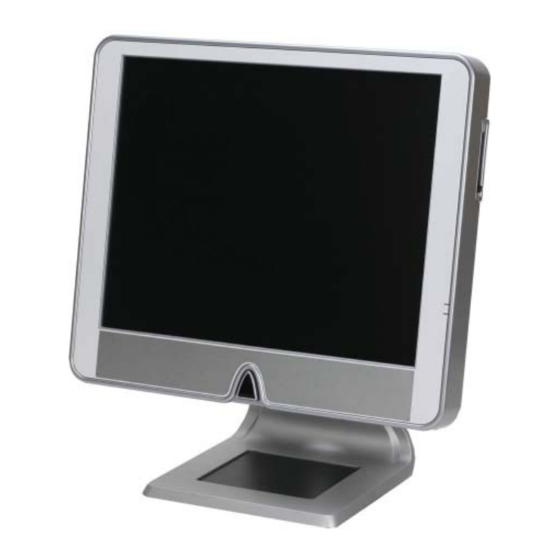
Chapter 1 Getting Started Congratulations on your purchase of a VITA 8000S. With a sleek design and small form factor, VITA 8000S can be placed anywhere for a feature-rich PC experience. -
Page 12: Mainboard Specifi Cations
VITA 8000S Mainboard Specifi cations Processor Support - Intel ® Pemtium 4, Pentium D(Dual Core), Celeron D @ 1066MHz FSB in the LGA 775 package Chipset - North Bridge: Intel ® 945G chipset - South Bridge: Intel ® ICH7 chipset... - Page 13 Getting Started Barebone Specifi cations LCD Panel - 17” TFT LCD panel Expansion Slot - One mini-PCI slot for optional 802.11b/g WLAN card Side I/O - 1 PS/2 mouse port - 1 PS/2 keyboard port - 4 USB 2.0 ports - 1 LAN jack - 3 audio jacks (Line-in / Line-out / MIC-in) - 1 brightness adjustment knob...
-
Page 14: Outlook Introduction
VITA 8000S Outlook Introduction Brighteness Adjustment Knob... - Page 15 Getting Started MIC-in Line-in Line-out USB 2.0 Ports Parallel Port AC Input Connector VGA Port Serial Port...
- Page 16 VITA 8000S PCMCIA Card Bus Slot Optical Storage Drive USB 2.0 Ports LAN Jack PS/2 Mouse Connector PS/2 Keyboard Connector Card Reader/ Slim Floppy Drive (Optional) Power Switch...
- Page 17 Getting Started...
-
Page 18: Chapter 2. System Assembly
System Assembly Chapter 3 Chapter 2 BIOS Setup System Assembly This chapter provides detailed information on system as- sembly. Follow all installation procedures carefuly. Use a grounded wrist strap before handling computer com- ponents. Static electricity may damage the components. -
Page 19: Introduction
VITA 8000S Introduction The built-in mainboard is designed for VITA 8000S only. Except the mainboard, the built-in components of the barebone include power supply. In this chapter we’ll show you how to install CPU and thermal kit, mini-PCI card, card reader, fl oppy drive, HDD, optical drive and memory module. -
Page 20: The Position Of The Key Parts
System Assembly The Position of the Key Parts Optical Drive Area CPU and Thermal Kit Area Hard Disc Drive Area Memory Module Area Floppy Drive / Card Reader / Mini PCI Card Area... - Page 21 VITA 8000S Take apart all the metal covers and trays in order. Layout is shown below.
-
Page 22: Installing The Mini-Pci Wlan Card(Optional)
System Assembly Installing the Mini-PCI WLAN Card 1. Connect the antennas to the mini- PCI Wireless LAN card. 2. Insert the mini-PCI Wireless LAN card to the slot using a 45 angle. 3. Press down the mini-PCI Wireless LAN card. The clips at each side of the slot will close and fi... -
Page 23: Installing The Floppy Drive / Card Reader Module
VITA 8000S Installing the Floppy Drive / Card Reader Module Floppy drive / Card reader tray Floppy drive Card reader 1. Put the fl oppy drive on the tray and line up the hook accordingly. 2. Lock three screws (M2.5 * L3) to fi x the fl... - Page 24 System Assembly 4. Insert the fl oppy drive cable into the connector and lock the cable. 5. Put the fl oppy door on the cage. 6. Lock the fl oppy door with a screw (M3 * L5). 7. Put the fl oppy drive module on the cage.
- Page 25 VITA 8000S 8. Lock the fl oppy drive module on the cage with two screws (M3 * L5). The fl oppy drive module installation is fi nished. 9. For installing the card reader mod- ule, please refer to the step 1-8 to assemble and fi...
- Page 26 System Assembly 12. Install the audio I/O door. This completes the card reader module installation. 13. Arrange the cable along the main- board and avoid the cable crossing the location of the memory module.
-
Page 27: Installing The Optical Drive Module
VITA 8000S Installing the Optical Drive Module Optical drive tray Optical drive 1. Put the optical drive on the tray. Line up the two hooks accordingly. 2. Lock two screws (M2 * L3) to fi x the optical drive to the tray. - Page 28 System Assembly 4. Connect the optical drive cable. 5. Lock two screws (M3 * L5) to fi x the optical drive module. The optical drive module installation is fi nished. 2-11...
-
Page 29: Installing The Hard Disc Drive (Hdd) Module
VITA 8000S Installing the Hard Disc Drive (HDD) Module HDD tray 1. Put the HDD on the tray. Line up the two hooks accordingly. 2. Lock two screws (M3 * L3.5) to fi x the HDD to the tray. 3. Put the HDD module on the cage. - Page 30 System Assembly 4. Connect the HDD cable. 5. Lock the screw (M3 * L5) to fi x the HDD module. The HDD module installation is fi nished. 2-13...
-
Page 31: Installing The Cpu And Thermal Kit
VITA 8000S Installing the CPU and Thermal Kit 1. Locate the CPU socket. Pull the lever away from the socket and raise it up, then lift up the cover. 2. Locate the gold arrow on the CPU and put the CPU onto the socket. - Page 32 System Assembly 5. Place the CPU heatsink onto the CPU socket. Make sure the four screws on the CPU heatsink fi t the corresponding screw holes on the mainboard. 6. Lock the screws in order as shown in the picture. Note: Do not begin to tighten any screws until these four screws are in place.
- Page 33 VITA 8000S 8. Connect the fan module power cable to mainboard. 10. Lock the fan module with the retain- ers. 11. Place the CPU door on the cage. 12. Lock the CPU door with four screws (M3 * L5). 2-16...
-
Page 34: Installing The Memory Module
System Assembly Installing the Memory Module 1. The memory module has only one notch on the center of module. The module will only fi t when oriented properly. 2. Push it until the golden fi nger on the memory module is deeply inserted into the slot. -
Page 35: Installing The Rear Cover (Desk Top Type)
VITA 8000S Installing the Rear Cover (Desk Top Type) 1. Place the rear cover on the cage. 2. Lock the rear cover with six screws (M3 * L7). 3. Place the stand and lock with two screws (M6 * L18). Using an electric screwdriver to lock the screws is recommended. - Page 36 System Assembly 5. This is your desktop style. 2-19...
-
Page 37: Installing The Rear Cover (Wallmount Type)
VITA 8000S Installing the Rear Cover (Wallmount Type) 1. Place the rear cover on the cage. 2. Lock the rear cover with six screws (M3 * L7). 3. This is your wallmount style. 2-20... -
Page 38: Chapter 3. Bios Setup
BIOS Setup Chapter 3 BIOS Setup This chapter provides information on the BIOS Setup program and allows you to confi gure the system for optimum use. You may need to run the Setup program when: An error message appears on the screen during the system booting up, and requests you to run SETUP. -
Page 39: Entering Setup
VITA 8000S Entering Setup Power on the computer and the system will start POST (Power On Self Test) process. When the message below appears on the screen, press <DEL> key to enter Setup. Press DEL to enter SETUP If the message disappears before you respond and you still wish to enter Setup, restart the system by turning it OFF and On or pressing the RESET button. - Page 40 BIOS Setup Control Keys Getting Help After entering the Setup menu, the fi rst menu you will see is the Main Menu. Main Menu The main menu lists the setup functions you can make changes to. You can use the control keys ( ↑↓...
-
Page 41: The Main Menu
VITA 8000S The Main Menu Standard CMOS Features Use this menu for basic system confi gurations, such as time, date etc. Advanced BIOS Features Use this menu to setup the items of special enhanced features. Advanced Chipset Features Use this menu to change the values in the chipset registers and optimize your system’s performance. - Page 42 BIOS Setup Set Supervisor Password Use this menu to set the supervisor password. Set User Password Use this menu to set the user password. Save & Exit Setup Save changes to CMOS and exit setup. Exit Without Saving Abandon all changes and exit setup.
-
Page 43: Standard Cmos Features
VITA 8000S Standard CMOS Features The items in Standard CMOS Features Menu are divided into several categories. Each category includes no, one or more than one setup items. Use the arrow keys to high- light the item and then use the <PgUp> or <PgDn> keys to select the value you want in each item. - Page 44 BIOS Setup [Access Mode] The settings are [CHS], [LBA], [Large], [Auto]. [Capacity] The formatted size of the storage device. [Cylinder] Number of cylinders. [Head] Number of heads. [Precomp] Write precompensation. [Landing Zone] Cylinder location of the landing zone. [Sector] Number of sectors. Drive A This item allows you to set the type of fl...
-
Page 45: Advanced Bios Features
VITA 8000S Advanced BIOS Features Boot Sequence Press <Enter> to enter the sub-menu and the following screen appears: 1st/2nd/3rd Boot Device The items allow you to set the sequence of boot devices where BIOS attempts to load the disk operating system. - Page 46 BIOS Setup Important Available settings for “1st/2nd/3rd Boot Device” vary depending on the bootable devices you have installed. if the system fails to boot from the 1st/2nd/3rd boot device. Hard Disk Boot Priority Press <Enter> to enter the sub-menu. Then you may use the arrow keys ( ↑↓ ) to select the desired device, and press <+>, <->...
- Page 47 VITA 8000S allowable temperature limit. Thermal Management This setting specifi es the thermal technologies implemented in the Pentium M processor. Limit CPUID MaxVal If you want to install WinNT 4.0 (or some other legacy OS) with the main board designed for Prescott P4 CPU, please set this item to [Enable] before OS instal- lation.
-
Page 48: Advanced Chipset Features
BIOS Setup Advanced Chipset Features Important Change these settings only if you are familiar with the chipset. It is strongly recommended that users should leave the settings to their default options. On-Chip Frame Buffer Size Frame Buffer is the video memory that stores data for video display (frame). This fi eld is used to determine the memory size for Frame Buffer. -
Page 49: Integrated Peripherals
VITA 8000S Integrated Peripherals OnChip IDE Device Press <Enter> to enter the sub-menu and the following screen appears: IDE HDD Block Mode Block mode is also called block transfer, multiple commands, or multiple sector read/write. If your IDE hard drive supports block mode (most new drives do), select [Enabled] for automatic detection of the optimal number of block read/writes per sector the drive can support. - Page 50 BIOS Setup Press <Enter> to enter the sub-menu and the following screen appears: USB Controller This setting allows you to enable/disable the onboard USB controller. Selecting [Enabled] enables the system to support both USB 1.1 and 2.0 spec. USB 2.0 Controller Set to [Enabled] if you need to use any USB 2.0 device in the operating system that does not support or have any USB 2.0 driver installed, such as DOS and SCO Unix.
- Page 51 VITA 8000S Onboard FDC Controller Select [Enabled] if your system has a fl oppy disk controller (FDD) installed on the system board and you wish to use it. If you install add-on FDC or the system has no fl oppy drive, select [Disabled] in this fi eld.
- Page 52 BIOS Setup 3-15...
-
Page 53: Power Management Setup
VITA 8000S Power Management Setup Important S3-related functions described in this section are available only when your BIOS supports S3 sleep mode. ACPI Function This item is to activate the ACPI (Advanced Confi guration and Power Management Inter- face) Function. If your operating system is ACPI-aware, such as Windows 98SE/2000/ME, select [Enabled]. - Page 54 BIOS Setup support S3 mode, system will enter S1 mode instead of S3 mode. PWRON After PWR-fail This item specifi es whether your system will reboot after a power failure or interrupt oc- curs. Available settings are: [Off] Leaves the computer in the power off state. [On] Leaves the computer in the power on state.
- Page 55 VITA 8000S POWER ON Function This controls how the PS/2 mouse or keyboard can power on the system. This function only supports wakeup from S3 mode. Important If you have changed this setting, you must let the system boot up until it enters the operating system, before this function will work.
-
Page 56: Pnp/Pci Confi Gurations
BIOS Setup PNP/PCI Confi gurations PCI/VGA Palette Snoop When set to Enabled, multiple VGA devices operating on different buses can handle data from the CPU on each set of palette registers on every video device. Bit 5 of the command register in the PCI device confi guration space is the VGA Palette Snoop bit (0 is disabled). -
Page 57: Pc Health Status
VITA 8000S PC Health Status Shutdown Temperature If the CPU temperature reaches the limit preset in this setting, the system will shotdown automatically. System/CPU Temperature, Vcc_DDR / Vccp/ Vcc5 / +12V / Vcc3_SB / VBat / Vcc3 / Fan1 Speed / Fan2 Speed / PSU FAN These items display the current status of all of the monitored hardware devices/compo- nents such as CPU voltage, temperatures and all fans’... -
Page 58: Load Fail-Safe/Optimized Defaults
BIOS Setup Load Fail-Safe / Optimized Defaults The two options on the main menu allow users to restore all of the BIOS settings to the default Fail-Safe or Optimized values. The Optimized Defaults are the default values set by the mainboard manufacturer specifi cally for optimal performance of the mainboard. The Fail-Safe Defaults are the default values set by the BIOS vendor for stable system performance. -
Page 59: Set Supervisor/User Password
VITA 8000S Set Supervisor / User Password When you select this function, a message as below will appear on the screen: Type the password, up to 8 characters in length, and press <Enter>. The password typed now will replace any previously set password from CMOS memory. You will be prompted to confi...