Table of Contents
Advertisement
Quick Links
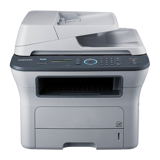
- Print/Copy Speed
SCX-4824FN : 24 ppm (A4) / 24 cpm (A4)
SCX-4828FN : 28 ppm (A4) / 28 cpm (A4)
- Print resolrution
: 1200 dpi effective output
- CPU : 360 Mhz
- PCL5e, PCL6, IBM ProPrinter, EPSON PS(4828FN)
Service Manual
DIGITAL LASER MFP
Model : SCX-4824FN/XBH
Basic : SCX-4824FN/SCX-4828FN
- Memory
SCX-4824FN : 64MB(Max. 320MB)
SCX-4828FN : 128MB(Max. 384MB)
- ADF : 30(4824FN) / 50(4828FN) Sheet
- MP : 1 Sheet
- Toner : 2K(Initial)/ 5K(Sales)
Advertisement
Table of Contents
Troubleshooting

Related Manuals for Samsung SCX-4824XBH


Summary of Contents for Samsung SCX-4824XBH
-
Page 1: Service Manual
Service Manual DIGITAL LASER MFP Model : SCX-4824FN/XBH Basic : SCX-4824FN/SCX-4828FN - Print/Copy Speed - Memory SCX-4824FN : 24 ppm (A4) / 24 cpm (A4) SCX-4824FN : 64MB(Max. 320MB) SCX-4828FN : 28 ppm (A4) / 28 cpm (A4) SCX-4828FN : 128MB(Max. 384MB) - Print resolrution - ADF : 30(4824FN) / 50(4828FN) Sheet : 1200 dpi effective output... - Page 2 GSPN (Global Service Partner Network) North America : service.samsungportal.com Latin America : latin.samsungportal.com CIS : cis.samsungportal.com Europe : europe.samsungportal.com Samsung Electronics Co.,Ltd. September. 2008 China : china.samsungportal.com Printed in Korea. Asia : asia.samsungportal.com Mideast & Africa : mea.samsungportal.com VERSION NO. : 1.00...
-
Page 3: Table Of Contents
Contents chapter 1 Precautions 1.1 Safety Warning …………………………………………………… 1-1 1.2 Caution for safety ………………………………………………… 1-2 1.3 ESD Precautions ………………………………………………… 1-5 1.4 Super Capacitor or Lithium Battery Precautions ……………… 1-5 chapter 2 Product spec and feature …………………………………………… 2-1 2.1.1 Product Overview …………………………………………… 2-1 …………………………………………………... - Page 4 Contents 3.2.10 Transfer roller ……………………………………………… 3-12 3.2.11 Holder Pad unit……………………………………………… 3-13 chapter 4 Alignment & Troubleshooting 4.1 Alignment and Adjustments……………………………………… 4-1 4.1.1 Control Panel overview ……………………………………… 4-1 4.1.2 Understanding The Status LED …………………………… 4-2 4.1.3 Paper path …………………………………………………… 4-3 4.1.4 Menu Map …………………………………………………… 4-10 4.1.5 Tech Mode ……………………………………………………...
- Page 5 Contents 5.7 ADF Ass’y ………………………………………………………… 5-19 5.8 Platen Ass’y ……………………………………………………… 5-21 5.9 OPE Unit ………………………………………………………… 5-23 5.10 Duplex Unit ……………………………………………………… 5-25 5.11 Fuser……………………………………………………………… 5-27 5.12 Cassette ………………………………………………………… 5-30 5.13 SCF ……………………………………………………………… 5-32 chapter 6 System Diagram 6.1 Block Diagram …………………………………………………… 6-1 6.2 Connection Diagram………………………………………………...
-
Page 6: Safety Warning
High voltages and lasers inside this product are dangerous. This printer should only be serviced by a suitably trained and qualified service engineer. (2) Use only Samsung replacement parts There are no user serviceable parts inside the printer. Do not make any unauthorized changes or additions to the printer, these could cause the printer to malfunction and create electric shock or fire haz- ards. -
Page 7: Caution For Safety
Take care not to cut or damage the power cable or plugs when moving the machine. (9) Use caution during thunder or lightening storms. Samsung recommend that this machine be disconnected from the power source when such weather conditions are expected. Do not touch the machine or the power cord if it is still connected to the wall socket in these weather conditions. -
Page 8: Handling Precautions
1.2.4 Assembly / Disassembly Precautions Replace parts carefully, always use Samsung parts. Take care to note the exact location of parts and also cable routing before dismantling any part of the machine. Ensure all parts and cables are replaced correctly. -
Page 9: Disregarding This Warning May Cause Bodily Injury
- The equipment shall be installed near the socket outlet and shall be accessible. - Be sure to fix and plug in the power cable securely after the installation so that no one trips over it. Service Manual Samsung Electronics... -
Page 10: Esd Precautions
2. Be sure to replace the battery with the same or equivalent type recommended by the manufacturer. 3. Super capacitor or Lithium batteries contain toxic substances and should not be opened, crushed, or burned for disposal. 4. Dispose of used batteries according to the manufacture? instructions. Service Manual Samsung Electronics... -
Page 11: Product Spec And Feature
Product spec and feature 2. Product spec and feature 2.1.1 Product Overview Concept Optimized Desktop MFP for Small Workgroup Entry SMB Target SCX-4824FN SCX-4828FN Service Manual Samsung Electronics... - Page 12 Product spec and feature 2.1.2.1 General Print Engine Items SCX-4824FN SCX-4828FN Packing Dimension System Memory Service Manual Samsung Electronics...
- Page 13 Product spec and feature Items SCX-4824FN SCX-4828FN Items SCX-4824FN SCX-4828FN Processor Memory Emulation Font fonts fonts Default Service Manual Samsung Electronics...
- Page 14 Product spec and feature Items SCX-4824FN SCX-4828FN Items SCX-4824FN SCX-4828FN Gray Scale Service Manual Samsung Electronics...
- Page 15 Product spec and feature Items SCX-4824FN SCX-4828FN Modem Speed Memory locations locations Functions Memory Back-up Service Manual Samsung Electronics...
-
Page 16: Paper Handling
Product spec and feature 2.1.2.6 Paper Handling Items SCX-4824FN SCX-4828FN Media Sizes Media types Sensing Paper empty sensor Paper empty sensor Media Sizes Media types Sensing Paper empty sensor Paper empty sensor Media Sizes Media types Sensing Output Stacking Service Manual Samsung Electronics... - Page 17 2.1.2.7 Consumables (CRU) Items SCX-4824FN SCX-4828FN T-D209S/MLT-D209L MLT-D209S/MLT-D209L 2.1.2.8 Consumables (FRU) Image Items Life Part code Transfer roller JC66-01218A JC96-05132A(220V) Fuser JC96-05133A(110V) Pick up rubber JC97-03062A Friction Pad (Cassette) JC96-04743A Friction Pad (ADF) JC97-01940A Pick up Assy(ADF) JC97-01962A Service Manual Samsung Electronics...
- Page 18 Product spec and feature 2.1.2.9 Options Items SCX-4824FN SCX-4828FN Memory Standard Service Manual Samsung Electronics...
-
Page 19: Model Comparison
Product spec and feature 2.1.3 Model Comparison Samsung Samsung SCX-4824FN SCX-4728FN M2727nf Speed Default Printer Processor Memory Emulation Modem Speed Scan Dimension Service Manual Samsung Electronics... -
Page 20: Summary Of Product
Document width guides ADF cover USB memory port Control panel Paper level indicator Output support Optional tray 2 Front cover Toner cartridge Manual tray paper width Manual tray guides Tray 1 Scanner lid Document input tray Scanner glass Service Manual Samsung Electronics... - Page 21 Product spec and feature 2.2.1.2 Rear View Extension telephone socket Handle (EXT) Control board cover Telephone line socket USB port Rear cover Network port Power receptacle 15-pin optional tray Power switch connection 2-11 Service Manual Samsung Electronics...
-
Page 22: System Layout
Product spec and feature 2.2.2 System Layout - Engine Layout DEVE FUSER DUPLEX CASSETTE - Scanner (ADF) Layout 2-12 Service Manual Samsung Electronics... - Page 23 Product spec and feature 2.2.2.1 Feeding 1) Separation method 2) Basic cassette 3) Pick-up roller 4) Registration roller 5) MP tray 6) Duplex unit 7) SCF (Second Cassette Feeder) Service Manual Samsung Electronics...
- Page 24 Product spec and feature 2.2.2.2 Transfer 2.2.2.3 Driver Ass’y 2.2.2.4 Fuser 1) Thermostat 2) Heat roller 3) Pressure roller 4) Items for safety Safety device 2.2.2.5 LSU (Laser Scanner Unit) Service Manual Samsung Electronics...
-
Page 25: Print Cartridge
Product spec and feature 2.2.2.6 Print Cartridge Service Manual Samsung Electronics... -
Page 26: Main Board
Interface Interface Interface Interface CHORUS3 CHORUS3 Network IC Network IC CHORUS3 CHORUS3 Network IC Network IC Serial Flash Serial Flash Serial Flash Serial Flash NOR Flash NOR Flash EEPROM EEPROM NOR Flash NOR Flash EEPROM EEPROM Service Manual Samsung Electronics... - Page 27 Product spec and feature 2.2.3.1(a) Asic(CHRUS3) Package Service Manual Samsung Electronics...
- Page 28 Product spec and feature 2.2.3.1(b) Memory 2.2.3.1(C) Interface - Device Service Manual Samsung Electronics...
- Page 29 Product spec and feature 2.2.3.2 SMPS & HVPS board 2.2.3.2(a) HVPS (High Voltage Power Supply) Service Manual Samsung Electronics...
- Page 30 Product spec and feature 2.2.3.2(b) SMPS (Switching Mode Power Supply) Service Manual Samsung Electronics...
- Page 31 24V : 3 5 7 9 24V : 3 5 7 9 5V : 11 13 15 CON2 5V : 11 13 15 CON2 (Heat Lamp (Heat Lamp CON.) CON.) PC22 PC22 250V 3.15A TLP3061F TLP3061F 250V 3.15A 2-21 Service Manual Samsung Electronics...
- Page 32 24V : 3 5 7 9 CON2 CON2 5V : 11 13 15 5V : 11 13 15 (Heat (Heat Lamp Lamp CON.) CON.) PC51 PC51 250V 3.15A TLP3061F 250V 3.15A TLP3061F 2.2.3.2(c) FUSER AC POWER CONTROL 2-22 Service Manual Samsung Electronics...
- Page 33 Product spec and feature 2.2.3.3 Fax Service Manual Samsung Electronics...
- Page 34 Product spec and feature 2.2.3.4 Scan main function Service Manual Samsung Electronics...
- Page 35 Product spec and feature 2.2.3.5 Engine F/W 2.2.3.5(a) Control Algorithm Item Description 2.2.3.5(b) Driver 2.2.3.5(c) Transfer Service Manual Samsung Electronics...
- Page 36 Product spec and feature 2.2.3.5(d) Fusing Error Description 2.2.3.5(e) LSU Error Description Polygon Motor Error Service Manual Samsung Electronics...
-
Page 37: S/W Descriptions
Product spec and feature 2.2.4 S/W Descriptions 2.2.4.1 Overview 2.2.4.2 Architecture Host Software is made up of Firmware is made up of Service Manual Samsung Electronics... -
Page 38: Data And Control Flow
Product spec and feature 2.2.4.3 Data and Control Flow The above Block Diagram is explained that: Host Side is made up of Service Manual Samsung Electronics... - Page 39 Product spec and feature Firmware Side is made up of In Printing, the two procedures are The additional printing function are realized in Service Manual Samsung Electronics...
-
Page 40: Disassembly And Reassembly
3. Unplug the power cord. 4. Use a flat and clean surface. 5. Replace only with authorized components. 6. Do not force plastic-material components. 7. Make sure all components are in their proper position. Service Manual Samsung Electronics... -
Page 41: Screws Used In The Printer
SCREW-TAPTITE;PWH,+,B,M3,L10,NI PLT,SWRCH18A ELA UNIT-FUSER 6003-000282 SCREW-TAPTITE;BH,+,-,B,M3,L8,ZPC(BLK),SWRCH18A,- 6003-000282 MEA-COVER FRONT SCREW-TAPTITE;BH,+,-,B,M3,L8,ZPC(BLK),SWRCH18A,- 6003-000196 SCREW-TAPTITE;PWH,+,B,M3,L10,NI PLT,SWRCH18A ELA HOU-MAIN LINE 6003-001256 SCREW-TAPTITE;BH,+,B,M4,L10,NI PLT,SWRCH18A 6003-000282 ELA UNIT-LSU SCREW-TAPTITE;BH,+,-,B,M3,L8,ZPC(BLK),SWRCH18A,- 6003-000282 ELA UNIT-LSU LD SCREW-TAPTITE;BH,+,-,B,M3,L8,ZPC(BLK),SWRCH18A,- 6003-000196 SCREW-TAPTITE;PWH,+,B,M3,L10,NI PLT,SWRCH18A 6003-000261 MEA UNIT-CASSETTE SCREW-TAPTITE;BH,+,-,B,M3,L6,ZPC(WHT),SWRCH18A,- 6003-000264 SCREW-TAPTITE;PWH,+,-,B,M3,L6,ZPC(WHT),SWRCH18A,- Service Manual Samsung Electronics... -
Page 42: General Disassembly
3.2.2 Rear Cover 1. Remove the Duplex unit. 2. Open the rear cover. And separate the rear cover from the locking by pulling the rear cover to the direction of arrow. Service Manual Samsung Electronics... -
Page 43: Right/Left Cover
1. Remove the one screw. And pull and release the 3. Pull the left cover to the direction of arrow and right cover somewhat. release it. 2. Release the right cover after unplug the 1 connector from Main PBA. Service Manual Samsung Electronics... -
Page 44: Adf Unit
Main board. And lift the Scan Assy to the direction of arrow. 3.2.4.1 ADF Unit 1. Unplug the harness after remove the cap 2. Lift up and release the ADF Assy. harness as shown below. Service Manual Samsung Electronics... - Page 45 Disassembly and Reassembly 3.2.4.2 Stacker TX 1. Remove the 2 screws from the bottom of ADF 2. Lift up and release the Stacker TX Assy. Service Manual Samsung Electronics...
- Page 46 1. Open the ADF cover and remove it. And remove the pick-up roller by following below sequence. Locking Locking 2. Remove the ADF engine unit after remove the 2 3. Remove the 2 screws of the ADF cover upper. screws from the bottom of SET. And then lift it up. Service Manual Samsung Electronics...
- Page 47 2. Remove the 2 connector and release the OPE unit. Hook Hook 3.2.4.5 CIS Unit 1. Remove the 4 screws of the Scan upper. 2. Remove the 4 screw and 1 CIS cable. And release the CIS unit. Service Manual Samsung Electronics...
-
Page 48: Middle Cover
2. Remove the 4 screw. And remove the fuser after by pushing both side and removing the hinge. remove the connector. CAUTION The fuser is very hot. So turn the printer off and wait until the printer to cool before replacing it. Service Manual Samsung Electronics... -
Page 49: Lsu
- Before disassembly, remove the cassette, Cover front, Cover left, Cover rear. 1. Remove the rear cover. Remove the Guide rear 2. Remove the 4 screw. And remove the fuser after by pushing both side and removing the hinge. remove the connector. 3-10 Service Manual Samsung Electronics... -
Page 50: Hvps/Smps/Main Board
1. Release the HVPS board after remove the 6 screws and 1 connector. 2. Release the SMPS board after remove the 4 3. Release the Main board after remove the 4 screws and 2 connector. screws and all harness. 3-11 Service Manual Samsung Electronics... -
Page 51: Transfer Roller
Disassembly and Reassembly 3.2.10 Transfer roller 1. Push HOLDER-TRANSFER, which holds the transfer roller and remove the roller from set. Caution - Be carefull not to touch the sponge of Transfer Roller. 3-12 Service Manual Samsung Electronics... -
Page 52: Holder Pad Unit
Disassembly and Reassembly 3.2.11 Holder Pad unit 1. Remove the CASSETTE from SET. 2. Disassemble HOLER-PAD after putting out three HOOKs 3-13 Service Manual Samsung Electronics... -
Page 53: Alignment & Troubleshooting
Engages the telephone line. Stops an operation at any time. In ready mode, clears/cancels the copy options, such as the Stop/Clear darkness, the document type setting, the copy size, and the number of copies. Start Starts a job. Service Manual Samsung Electronics... -
Page 54: Understanding The Status Led
The color of the Status LED indicates the machine’s current status. Status Description button is pressed, it switches to on-line automatically. Green Blinking the computer. the tray, so that the machine cannot continue the job. Blinking cleared. Service Manual Samsung Electronics... -
Page 55: Paper Path
Alignment & Troubleshooting 4.1.3 Paper path Scanner Part PICK-UP COVER OPEN COVER OPEN ADF-UPPER ADF-UPPER EXIT SCAN UPPER SCAN UPPER Engine Part DEVE FUSER DUPLEX CASSETTE Service Manual Samsung Electronics... -
Page 56: Clearing Document Jams
3. Rotate the bushing on the right end of the ADF roller toward the ADF (1) and remove the roller from the slot (2). Pull the document gently to the left and out of the ADF. Service Manual Samsung Electronics... -
Page 57: Exit Misfeed
3. Close the scanner lid. Then load the removed pages back into the ADF. Service Manual Samsung Electronics... -
Page 58: Clearing Paper Jams
If the paper does not move when you pull, or if you do not see the paper in this area, check In the toner cartridge area. 3. Insert the tray back into the machine. Printing automatically resumes. Service Manual Samsung Electronics... - Page 59 2. Remove the jammed paper by gently pulling it 3. Open the front cover and close it. The machine straight out as shown below. will resume printing. 3. Replace the toner cartridge and close the front cover. Printing automatically resumes. Service Manual Samsung Electronics...
- Page 60 If the paper does not come out with the duplex unit, remove the paper from the bottom of the machine. Guide rear 4. Close the rear cover. Printing automatically resumes. any resistance removing the paper, stop pulling and go to step 3. Service Manual Samsung Electronics...
- Page 61 1. Pull the optional tray open. 4. Remove the jammed paper by gently pulling the paper straight up and out. 5. Insert the trays back into the machine. Printing automatically resumes. Service Manual Samsung Electronics...
-
Page 62: Menu Map
The control panel provides access to various menus to set up the machine or use the machine’s functions. These menus can be accessed by pressing Menu. Refer to the following diagram. Menus available in Fax, Copy, or Scan mode vary. 4-10 Service Manual Samsung Electronics... - Page 63 An asterisk (*) appears next to the selection on the display, indicating that it is now the default. 8. To exit the menu, press the Back button repeatedly, or the Stop button. Note - If you want to set the basic menu items, please consult the user guide. 4-11 Service Manual Samsung Electronics...
-
Page 64: Tech Mode
Protocol Pause Time Dram Test Configuration Dial Mode Rom Test Modem Speed Pattern Test Error Info Error Rate Shading Test Usage Page Component Check Clear All Mem Service Support Clear Counts Flash Upgrade Silence Time 4-12 Service Manual Samsung Electronics... -
Page 65: Data Setup
India Brazil France Oman Italy Poland Spain Bangladesh Austria Kuwait Netherlands Moroco Belgium Algeria Portugal Pakistan Sweden Country Norway Bahrain Denmark Srilanka Finland Saudi Arabia Switzerland Chile Greece Peru Ireland Argentina Turkey Romania Bulgaria Czech 4-13 Service Manual Samsung Electronics... -
Page 66: Flash Upgrade
1. sending and receiving fax must be the same model. 2. A sending fax must be set up as ECM mode, and a receiving memory must be set up as 100%. If not, the function operates abnormally 4-14 Service Manual Samsung Electronics... -
Page 67: Adjust Shading
4) Scroll to Shading Test and Press OK. 5) Select Shading&Print appears on the bottom line and press OK. 6) Your machine picks up the paper and adjusts the shading value. 7) After adjusting, shading value will be printed with graphic image. 4-15 Service Manual Samsung Electronics... - Page 68 Tel. No, Model, Server Port (that is connected to), Status, Serial Number, Firmware Version, Engine Version, Emulation Version It will then be necessary to manually request for another call setup to the desired MFP before any RDS function can be reattempted. will be released / disconnected from the MFP-side. 4-16 Service Manual Samsung Electronics...
-
Page 69: Machine Test
2. Push the SET UP button then an image will be scanned. print out. 4. If the printed image is different to the image, the CCD is defect. NOTICE : When you test CCD, make sure that the cover is closed. 4-17 Service Manual Samsung Electronics... - Page 70 Use this list to check for send and receive errors. If a communication error occurs while the OTHER ITEM This list provides a list of the user system data settings and tech mode settings. 4-18 Service Manual Samsung Electronics...
- Page 71 Alignment & Troubleshooting supplies information report 4-19 Service Manual Samsung Electronics...
-
Page 72: Edc Mode
Alignment & Troubleshooting 4.1.6 EDC Mode EDC Mode is independently controled system f/w and diagnose printer’s each function. 2. To enter the EDC Mode, Push the button like next time. 4-20 Service Manual Samsung Electronics... - Page 73 Description Regi/Feed/Exit Sensor Empty 2. Motor Test Item Description Main Mtr Nor. Slow displayed. 3. Fan Test Item Description Fuser Fan SMPS Fan 4. Clutch Test Item Description Pick up Clutch displayed. Regi Clutch displayed. 4-21 Service Manual Samsung Electronics...
- Page 74 Alignment & Troubleshooting 5. Fuser Ctrl Item Description Temp Control display Fuser Temp. 6. LSU Control Item Description will be displayed after 10 seconds will be displayed. will be displayed. 7. DEV Control Item Description Dev Bias 4-22 Service Manual Samsung Electronics...
-
Page 75: Abnormal Image Printing And Defective Roller
Block Spot and Periodic Band Supply Roller 47.1mm Periodic Band by little difference of density Developing Roller 35.2mm Transfer Roller 47mm Ghost, Damaged Image by abnormal transfer 77.8mm Black Spots or Vertical Black Band 62.8mm Blackground 37.7mm Blackground 4-23 Service Manual Samsung Electronics... -
Page 76: Error Message
Check the server settings and the failed. network cable. Data Read Fail Time expired while reading data. Try again. Check USB Mem. Data Write Fail Storing to the USB memory failed. Check the available USB memory Check USB Mem. space. 4-24 Service Manual Samsung Electronics... - Page 77 Not Assigned The speed button or speed dial Enter the number manually using the number you tried to use has no number keypad or store the number or number assigned to it. address. 4-25 Service Manual Samsung Electronics...
- Page 78 Send Error There is a problem in POP3. (POP3) Send Error There is a problem in SMTP. Change to the available server. (SMTP) Send Error There is a problem on the network interface card. correctly. 4-26 Service Manual Samsung Electronics...
- Page 79 Do not turn the power off when this Please Wait... a change in the system setting or message is showing. Changes may when you back up a data. not be saved and datas can be lost. 4-27 Service Manual Samsung Electronics...
-
Page 80: Troubleshooting
Power On - No Power - Power Module error - Main PBA error - Panel PBA error Refer to Ready or Power save Error Message Test Print printing Refer to "Solution Quality is of Image Problem" 4-28 Service Manual Samsung Electronics... -
Page 81: The Cause And Solution Of Bad Image
3. Partly depression or Replace the transfer roller if deformation on the surface of occurred as No. 3. the transfer roller. 4-29 Service Manual Samsung Electronics... - Page 82 If the problems are not solved, substances are on the OPC Drum. replace the toner cartridge. 6. Partly depression or Replace the transfer roller if deformation on the surface of the occured as NO.6 transfer roller 4-30 Service Manual Samsung Electronics...
- Page 83 Charge roller = 26.7mm in the OPC. Supply roller = 47.1mm 2. If the malfunction persists, Develop roller = 35.2mm replace the toner cartridge. Transfer roller = 47mm 4-31 Service Manual Samsung Electronics...
- Page 84 3. Clean the inside of the set against the paper particles and foreign matter in order not to cause the trouble. 4-32 Service Manual Samsung Electronics...
- Page 85 No3 : Clean up the contaminated between the high voltage terminal in area by the toner. in the set. 4. Abnormal output problems are not solved by the above four instructions. 4-33 Service Manual Samsung Electronics...
- Page 86 1. Clean the high voltage charge on due to the bad contacts between terminal. power supply in the side of the Toner cartridge and charge terminal by the above direction 1 and 2. 3. VD0 signal of the Main PBA 4-34 Service Manual Samsung Electronics...
- Page 87 2. The life of the Toner cartridge shake the toner cartridge. has expired. 3. The toner level is not even on Replace the toner cartridge and the toner cartridge roller due to the try to print out. bad blade. 4-35 Service Manual Samsung Electronics...
- Page 88 Clean the bushing part of the 4. Is the movement(Up and Down) transfer roller. 1. If the problem is still not solved, replace the toner cartridge. 2. Gently shake the toner cartridge. 4-36 Service Manual Samsung Electronics...
- Page 89 3. The life of toner cartridge is expired. solved by the above directions 1-2. If not solved by the direction 3, 4. Transfer roller lifetime(50K sheets) check the transfer roller lifetime has expired. and replace it. Continue.. 4-37 Service Manual Samsung Electronics...
- Page 90 1 hour after power on 5. Abnormal low temperature before using printer. (below 10 ). Occur in the toner cartridge, 6. Damaged cleaning blade in the replace the toner cartridge and toner cartridge. try to print out. 4-38 Service Manual Samsung Electronics...
- Page 91 Digital Printer Digital Printer Select 'Thick Mode' on paper type thicker than normal paper or menu from the software application , higher and after using returning to the transfer voltage is original mode is recommended. required. 4-39 Service Manual Samsung Electronics...
- Page 92 Digital Printer Digital Printer Disassemble the fuser and remove the contaminated toner particles on The temperature of the fuser is the roller and clean the foreign maintained high. matter between Thermistor and (Caution: can be deformed) 4-40 Service Manual Samsung Electronics...
- Page 93 2. If the transfer roller is contaminated, run PC Cleaning contaminated, stains on the face of Mode Print 2 or 3 times. page will occur. And perform Self-Test 2 or 3 times to remove contamination. 4-41 Service Manual Samsung Electronics...
- Page 94 1. Replace the transfer roller if contaminated severely. 2. Disassemble the fuser and clean 2. 62.8mm : Pressure roller is contaminated. (Pressure roller). And check the Thermistor. If contaminated, clean the area not to be deformed. 4-42 Service Manual Samsung Electronics...
- Page 95 Digital Printer Digital Printer 1. Check if the Ground-OPC is Bad ground contacts in OPC and/or defective(set inside right side). toner cartridge. 2. Remove contamination of the terminals of the toner cartridge and the unit. 4-43 Service Manual Samsung Electronics...
- Page 96 EDC Mode to check if the Solenoid is normal. 2. Abnormal solenoid. 2. If not solved by the above directions 1-2, Replace the engine board. 3. Turn the power off, delete the data of PC and try printing again. 4-44 Service Manual Samsung Electronics...
-
Page 97: The Cause And Solution Of The Bad Discharge
4.2.3 The cause and solution of the bad discharge 1) Wrong Print Position Description : Printing begins at wrong position on the paper. rong sense time caused by defective Replace the defective actuator feed sensor actuator. 4-45 Service Manual Samsung Electronics... - Page 98 Replace the Main PBA and/or slot between shaft-pickup and Sensor. housing-pickup opens or is broken away. 5. If the paper feeds into the printer and Jam 0 occurs, perform EDC Mode to check feed-sensor of the engine board. 4-46 Service Manual Samsung Electronics...
- Page 99 1. Replace the Main PBA. stuck in the discharge roller and the 2. Reassemble the Actuator-Feed fuser just after passing through the and Spring-Actuator if the Actuator-Feed, Feed Actuator movement is bad. may be defective. 4-47 Service Manual Samsung Electronics...
- Page 100 : Clean the surface of the pressure roller with dry gauze. ¥ Remove the toner particles stained on the rib. 3. Paper is accordion in the fuser. ¥ Check the assemblage and performance of the exit. 4-48 Service Manual Samsung Electronics...
- Page 101 2nd exit roller after reach to a registration sensor. checking its operation. 2. A case that a paper jam occurs on (B) after it is reversed: replace a duplex roller after checking its operation 4-49 Service Manual Samsung Electronics...
- Page 102 (the solenoid does not work properly): Perform EDC Mode. Clean the pad friction with soft 3. Pad-Friction is contaminated cloth dampened with IPA with foreign matter.(oil...) (Isopropyl Alcohol). Use the smooth paper. 4. The face of paper is blended. 4-50 Service Manual Samsung Electronics...
- Page 103 2. Clean the surface of the heat roller with IPA or water 3. Check the warp or separation of the print claw and the holder plate claw, and then manage it. 4-51 Service Manual Samsung Electronics...
- Page 104 1. Paper is too much thin. in the OPC. Remove the paper while turning 2. The face of paper is curled. the OPC against the ongoing direction. Clean fingerprints on the OPC softly with soft cloth dampened with tissue. 4-52 Service Manual Samsung Electronics...
-
Page 105: The Cause And Solution Of The Malfunction
Check whether the overheat mode circuit operates normally or not. 4. It could not operate Replace the fuser. due to a gear of a fuser is melted. 4-53 Service Manual Samsung Electronics... - Page 106 Alignment & Troubleshooting 2) LSU Error Description : “PMOTOR ERROR/HSYNC ERROR’ connector is disconnected or not. Replace a main board if the same error occurs again after replacing motor is rotating or not. 4-54 Service Manual Samsung Electronics...
- Page 107 3) Not function of the gear of the fuser due to melting away Description : The motor breaks away from its place due to gear melting away. 1. Replace the Fuser. 2. Replace the Main PBA. 3. Replace the SMPS. 4-55 Service Manual Samsung Electronics...
- Page 108 Description : Paper empty error message is displayed on LCD when paper is loaded in the cassette. 1. Bending or deformation Replace the defective actuator. of the actuator of the paper sensor. 2. The function of the Replace the Sensor PBA. engine board is defective 3. Check the Connector. 4-56 Service Manual Samsung Electronics...
- Page 109 Description : Paper empty error message does not display when the paper cassette is empty. 1. Bending or deformation Replace the defective actuator. of the actuator of the paper sensor. 2. The function of the Replace the engine board. engine board is defective 4-57 Service Manual Samsung Electronics...
- Page 110 Guide rear if defective. may be defective. 1. Check the insertion of the 2. Check the connector and circuit of the cover switch department 2. Replace the Main Control in the Main Control board. 4-58 Service Manual Samsung Electronics...
- Page 111 Description : The Error LED does not come on even when the printer cover is open 1. Check the insertion of the 1. Check the connector and circuit of the cover switch department 2. Replace the Main Control in the Main Control board. Perform EDC test 4-59 Service Manual Samsung Electronics...
- Page 112 1. Check if the power input or SMPS. and SMPS output are normal. 2. Check the inferiority 1. Replace the control board. 2. Replace the OP panel. front-cover if the OP panel does not appear after normal warming-up. 4-60 Service Manual Samsung Electronics...
- Page 113 9) Vertical Line Getting Curved Description : When printing, vertical line gets curved. unstable in the Main Control board EDC Mode: 1. Replace theToner Joint PBA. 2. Chect the Deve PBA 2. Replace the MainPBA. in the Toner Cartridge. 4-61 Service Manual Samsung Electronics...
-
Page 114: The Cause And Solutions Of Bad Environment Of The Software
4. Check if the printer cable is If the scanner needs to be connected to the directly connected to peripheral devices printer, first the remove the scanner from the PC to see if the printer is properly working alone. 4-62 Service Manual Samsung Electronics... - Page 115 If not solved, double-click the printer in my computer If the regular fonts are not printed this time again. the cable must be defective so replace the cable with new one. 4-63 Service Manual Samsung Electronics...
- Page 116 Delete the unnecessary files to secure (The printing job sometimes stops or due enough space of the hard disk and start to insufficient virtual memory, but it actually printing job again. comes from the insufficient space of the hard disk.) 4-64 Service Manual Samsung Electronics...
- Page 117 If you intend to delete the current document being printed, the data being transferred to the printer will be put out and then the document is removed. Before choosing the document, the menu is still inactive. spool manager. 4-65 Service Manual Samsung Electronics...
-
Page 118: Fax & Phone Problems
Try to replace the OPE Ass'y. 3. Check the connection of Check the Speaker connection, and try to replace it. 4. Check if the SPEAKER , try to replace the Main B'd. is connected correctly. 4-66 Service Manual Samsung Electronics... - Page 119 ON KEY is pressed, check to catch the Main PBA, try to replace the The problem still persists, then 3. Check the connection of in sequence. Notes: Product supports the MF type only. 4-67 Service Manual Samsung Electronics...
- Page 120 2. Check if you can If the MODEM testing is abnormal, catch a RECEIVE tone while try to replace the Main B'd. MODEM testing in the 4-68 Service Manual Samsung Electronics...
- Page 121 2. Check the RECEIVE condition by trying to forward a FAX to another fax machine from the forwarding side FAX. 3. Check if the telephone line connected to the Product is contaminated or gets stripped off or down. 4-69 Service Manual Samsung Electronics...
- Page 122 1.Check if there is NOISE If it makes NOISE while when pressing on-hook dial. on-hooking, replace or repair the telephone line. 2.Check the RECEIVE condition by trying to receive a FAX at another fax machine. 4-70 Service Manual Samsung Electronics...
- Page 123 (Refer to 'Defective FAX RECEIVE'.) 2. Ask to the forwarding Check if the FAX status of the side, check the image quality of another forwarding side is also normal. machine receiving a FAX additionally sent to. 4-71 Service Manual Samsung Electronics...
- Page 124 Description : The phone is ringing continuously, but it cannot receive. Even when the RECEIVE Mode is Check if the RECEIVE Mode is changed to FAX MODE, it cannot MODE or FAX MODE. the Main B'd in sequence. 4-72 Service Manual Samsung Electronics...
- Page 125 Description : The received data is reduced by more than 50% in the printing. After checking the data of the Check the FAX status of the forwarding side, correct the forwarding side. FAX of the forwarding side. 4-73 Service Manual Samsung Electronics...
- Page 126 MODE, reset it to the 1. Check if the RECEIVE Mode is FAX MODE. MODE or FAX MODE. 2. Even after the RECEIVE Mode is changed to the FAX Mode, it cannot receive, then try to B'd in sequence. 4-74 Service Manual Samsung Electronics...
-
Page 127: Copy Problems
1. Check the Scan-Cover open. original. Remake shading profile in the 2. Check shading profile. tech mode. Replace U60 if it is defective. 3. Check white/black reference . U60-154 = 0.5V voltage in Main PBA. . U60-155 = 3.3V 4-75 Service Manual Samsung Electronics... - Page 128 2) White Copy Description : White page is printed out when Copy. Check the CIS harness contact. 1. Check the CIS problem in Main PBA. Remake shading profile in the 2. Check shading profile. tech mode. 4-76 Service Manual Samsung Electronics...
- Page 129 CIS carriage part. If any driver is defective, replace it. . Connection PBA U4-1, 19 or 2. Check the Motor Driver in Driver PBA. U5-1, 19=0V to 24V swing signal when operating. 4-77 Service Manual Samsung Electronics...
- Page 130 Remake shading profile in the 1. Check shading profile. tech mode. The gap above 0.5 mm can 2. Check the gap between cause a blurred image. original and scanner glass. See "Print" troubleshooting. 3. Check printing quality. 4-78 Service Manual Samsung Electronics...
-
Page 131: Scanning Problems
(Refer to User's Manual.) If copy function works, replace the Main PBA. 3. Check if copy function If copy function doesn't work, operates normally. replace the CIS Ass'y and try again. 4-79 Service Manual Samsung Electronics... - Page 132 If the resolution is set to low, let 2. Check if the resolution is the user be acquainted with the set too low in PC Scan options. using method well. (Refer to User's Manual.) 4-80 Service Manual Samsung Electronics...
- Page 133 - CPU : 360 Mhz - PCL5e, PCL6, IBM ProPrinter, EPSON PS(4828FN) - Memory SCX-4824FN : 64MB(Max. 320MB) SCX-4828FN : 128MB(Max. 384MB) - ADF : 30(4824FN) / 50(4828FN) Sheet - MP : 1 Sheet - Toner : 2K(Initial)/ 5K(Sales) Service Manual Samsung Electronics...
-
Page 134: Thumbnail
ExplodedView and Parts Thumbnail 5.1 Main 5.2 Cover Ass'y 5.3 Cover Middle 5.4 Frame 5.5 Main Drive 5.6 Scan Ass’y 5.7 ADF Ass’y 5.8 Platen Ass’y 5.10 Duplex Unit 5.9 OPE Unit 5.11 Fuser 5.12 Cassette 5.13 SCF Service Manual Samsung Electronics... -
Page 135: Main
ExplodedView and Parts 5.1 Main Service Manual Samsung Electronics... - Page 136 JC97-03221A MEA-COVER LEFT 5.1-17 JC97-03017A MEA UNIT-CASSETTE 5.1-18 JC97-03222A MEA-COVER FRONT 5.1-19 JC96-05078A ELA HOU-COVER-MIDDLE 5.1-20 JC96-05074Q ELA HOU-SCAN_LOW 5.1-21 JC96-04823B CARTRIDGE-TONER 5.1-22 JC63-01926A COVER-H_FAX_BOARD 5.1-23 6003-000196 SCREW-TAPTITE 5.1-24 JC92-01746A PBA SUB-MODEM 5.1-25 3903-000146 CBF-POWER CORD Service Manual Samsung Electronics...
-
Page 137: Cover Ass'y
ExplodedView and Parts 5.2 Cover Ass’y Service Manual Samsung Electronics... - Page 138 JC97-03015A MEA UNIT-COVER_REAR 5.2-3-1 JC63-01526A COVER-REAR 5.2-3-2 JC61-02399A GUIDE-CHANGE_DUP 5.2-3-3 JC72-01444A SPONGE-GUIDE CHANGE DUP 5.2-3-4 JC72-01445A SPONGE-COVER REAR 5.2-4 JC96-05079A ELA HOU-COVER-RIGHT 5.2-4-1 JC63-01925B COVER-RIGHT 5.2-4-2 JC63-01928B COVER-RIGHT DIMM 5.2-4-3 JC72-01461A SPONGE-SIDE BOTTOM R 5.2-4-4 JC72-01462A SPONGE-SIDE FRONT Service Manual Samsung Electronics...
-
Page 139: Cover Middle
ExplodedView and Parts 5.3 Cover Middle Service Manual Samsung Electronics... - Page 140 JC61-02584A STACKER-RX SMALL 5.3-4 JC63-01913A GROUND-BRUSH 5.3-5 JC72-01343A PMO-SUB_M_STACKER 5.3-6 JC63-01921A COVER-MIDDLE 5.3-7 JC63-01927A COVER-L_FAX_BOARD 5.3-8 JC61-02701A HOLDER-ACTUATOR BINFUL 5.3-9 JC66-02009A ACTUATOR-BIN FULL 5.3-10 0604-001095 PHOTO-INTERRUPTER 5.3-11 6003-000196 SCREW-TAPTITE JC39-00971A HARNESS-BIN FULL UPPER JC39-00949A HARNESS-SPEACKER JOINT Service Manual Samsung Electronics...
-
Page 141: Frame
ExplodedView and Parts 5.4 Frame1 Service Manual Samsung Electronics... -
Page 142: Frame
ExplodedView and Parts 5.4 Frame2 5-10 Service Manual Samsung Electronics... - Page 143 JC61-00915A STOPPER-M-PICK UP_R2 5.4-26 JC97-03062A MEA UNIT-PICK UP 5.4-26-1 JC73-00265A RUBBER PICK_UP 5.4-26-2 JC61-00910A HOUSING-M-PICK UP 5.4-26-3 JC61-00909A HOUSING-M-PICK UP_R2 5.4-27 JC61-00587A BUSH-M-PICK_UP R2 5.4-28 JC66-01660A SHAFT-FEED 5.4-29 JC66-01634A GEAR-FEED DR 16 5.4-30 JC63-01614A GROUND-GUIDE TR 5-11 Service Manual Samsung Electronics...
- Page 144 JC61-02308A SUPPORT-ROLLER 5.4-59 JC66-01662A ROLLER-EXIT F/DOWN 5.4-63 JC63-01916A SHIELD-CONTROLLER 5.4-64 JC63-01573A SHIELD-SMPS 5.4-65 JC62-00461A INSULATION-SMPS 5.4-66 JC61-40001A FOOT-ML80 5.4-67 JC70-00546A ADJUST-MANUAL L 5.4-68 JC70-00547A ADJUST-MANUAL R 5.4-69 JC70-00304A ADJUST RACK-M-MANUAL 5.4-71 JC66-00387A GEAR-RACK_PINION 5.4-72 JC66-01647A ACTUATOR-FEED 5-12 Service Manual Samsung Electronics...
- Page 145 JC72-00985A PMO-PLATE GUIDE DEVE_R 5.4-104 6107-001370 SPRING TR 5.4-105 JC61-02468A BUSH-TR_L 5.4-106 JC65-00033A TERMINAL SPRING TR 5.4-107 JC61-00588A PMO-BUSHING_TR(L) 5.4-108 JC61-02304A GUIDE-HOLDER_TR 5.4-109 JC61-00553A SPRING ETC-ES (Guide holder TR) 5.4-110 JC61-02231A HOLDER-TRANSFER 5.4-111 JC66-01649A LINK-COVER_REAR 5-13 Service Manual Samsung Electronics...
- Page 146 Frame Parts List SA : SERVICE AVAILABLE, SNA : SERVICE not AVAILABLE Drawer# SEC_Code Description QT’y Service Remark 5.4-112 6107-001172 SPRING-CS 5.4-114 JC97-03067A MEA UNIT-GUIDE REAR 5.4-115 JC61-00424A BUSH-4 5.4-116 JC39-00856A HARNESS-CCD HOME 5.4-117 JC39-00945A HANESS-FUSER SMPS 5-14 Service Manual Samsung Electronics...
-
Page 147: Main Drive
ExplodedView and Parts 5.5 Main Drive 5-15 Service Manual Samsung Electronics... - Page 148 JC66-01798A GEAR-OPC CLUTCH 29 5.5-11 JC66-01637A GEAR-FUSER DR OUT 37 5.5-12 6031-000023 WASHER-PLAIN 5.5-13 JC61-02227A BRACKET-MOTOR 5.5-14 JC31-00090A MOTOR BLDC 5.5-15 6003-000269 SCREW-TAPTITE 5.5-18 6044-001130 RING-C 5.5-19 JC66-00340A GEAR HUB CLUTCH 5.5-20 6107-001372 SPRING CLUTCH 5-16 Service Manual Samsung Electronics...
-
Page 149: Scan Ass'y
ExplodedView and Parts 5.6 Scan Ass’y 5-17 Service Manual Samsung Electronics... - Page 150 5.6-0 JC96-05074D ELA HOU-SCAN_HIGH SCX-4828FN JC96-05461A ELA HOU-SCAN_LOW SCX-4824FN 5.6-1 JC67-00304A CAP-ADF CONNECTOR 5.6-2 JC96-05091A ELA HOU-ADF 5.6-3 JC96-05095A ELA HOU-PLATEN_HIGH SCX-4828FN JC96-05097A ELA HOU-PLATEN_LOW SCX-4824FN 5.6-4 JC96-05094D ELA HOU-OPE SCX-4828FN JC96-05460A ELA HOU-OPE SCX-4824FN 5-18 Service Manual Samsung Electronics...
-
Page 151: Adf Ass'y
ExplodedView and Parts 5.7 ADF Ass’y 5-19 Service Manual Samsung Electronics... - Page 152 ELA HOU-ADF 5.7-3 6003-000196 SCREW-TAPTITE 5.7-4 JC96-05092A ELA HOU-ADF MOTOR 5.7-5 JC96-05093A ELA HOU-ADF LOWER 5.7-6 JC97-01962A MEA UNIT-PICKUP DELL 5.7-7 JC97-03223A MEA-ADF UPPER 5.7-8 JC97-03224A MEA-COVER OPEN 5.7-9 JC97-03225A MEA-COVER PLATEN 5.7-10 JC97-03226A MEA-TX STACKER 5-20 Service Manual Samsung Electronics...
-
Page 153: Platen Ass'y
ExplodedView and Parts 5.8 Platen Ass’y 5-21 Service Manual Samsung Electronics... - Page 154 5.8-1-10-17 JC63-01803A COVER-FFC 5.8-1-11 JC92-02065A PBA-USB HOST SCX-4828FN 5.8-2 JC97-03227A MEA-SCAN UPPER 5.8-2-1 0203-001266 TAPE-DOUBLE FACE 5.8-2-2 0203-001267 TAPE-DOUBLE FACE 5.8-2-3 JB01-00002A GLASS-PLATEN 5.8-2-4 JC63-01906A SHEET-SHADING 5.8-2-5 JC63-01923A COVER-SCAN UPPER 5.8-2-6 JC97-03237A MEA HOU-ADF SHEET 5-22 Service Manual Samsung Electronics...
-
Page 155: Ope Unit
ExplodedView and Parts 5.9 OPE Unit 5-23 Service Manual Samsung Electronics... - Page 156 JC63-00076A COVER-WINDOW SF-530 5.9-4 6003-000196 SCREW-TAPTITE 5.9-5 JC64-00386A KEY-EXTRA 5.9-6 JC64-00387A KEY-FAX 5.9-7 JC64-00388A KEY-MENU 5.9-8 JC64-00389A KEY-OK 5.9-9 JC64-00392A KEY-STATUS 5.9-10 JC64-00393A KEY-STOP 5.9-11 JC64-00394A KEY-TEL 5.9-12 JC64-00410A KEY-START 5.9-13 JC92-02019A PBA SUB-OPE 5.9-14 JC63-01802A COVER-LCD 5-24 Service Manual Samsung Electronics...
-
Page 157: Duplex Unit
ExplodedView and Parts 5.10 Duplex Unit(Only SCX-4828FN) 12-1 12-2 12-1 12-2 5-25 Service Manual Samsung Electronics... - Page 158 JC96-04983A ELA UNIT-ROLLER_DUP 5.10-12-1 JC66-00901A ROLLER-FEED_DUP 5.10-12-2 6044-000107 RING-C 5.10-13 JC61-02235A BRACKET-DUPLEX_ALIGN 5.10-14 6002-000440 SCREW-TAPPING 5.10-15 JC61-02314A GUIDE-DUPLEX_UPPER 5.10-16 JC66-00896A ROLLER-M-IDLE_ DUP 5.10-17 JK72-00058A PCT-SILP WASHER 5.10-18 JC66-00444A SHAFT-IDLE ROLL, DUP 5.10-19 6107-001156 SPRING-TS 5.10-20 6003-000196 SCREW-TAPTITE 5-26 Service Manual Samsung Electronics...
-
Page 159: Fuser
ExplodedView and Parts 5.11 Fuser 5-27 Service Manual Samsung Electronics... - Page 160 JC66-01597A LEVER-LINK JAM_L 5.11-27 6107-001246 SPRING-CS 5.11-28 6044-000159 RING-C 5.11-29 6107-001361 SPRING-ES 5.11-30 4713-001212 LAMP-HALOGEN 220V 4713-001211 LAMP-HALOGEN 110V 5.11-31 JC67-00266A CAP-LAMP_L 5.11-32 JC67-00267A CAP-LAMP_R 5.11-33 JC66-01638A GEAR-FUSER RDCN 28-20 5.11-34 JC66-00056A GEAR-MPF 5 5.11-35 6031-001051 WASHER-PLAIN 5-28 Service Manual Samsung Electronics...
- Page 161 SA : SERVICE AVAILABLE, SNA : SERVICE not AVAILABLE Drawer# SEC_Code Description QT’y Service Remark 5.11-36 6044-000001 RING-CS 5.11-37 0604-001095 PHOTO-INTERRUPTER 5.11-38 JC61-02520A PLATE-ACTUATOR 5.11-39 JC39-00946A HARNESS-FUSER AC 5.11-40 JC39-00819A HARNESS-FUSER JOINT 5.11-41 JC39-00823A HARNESS-EXIT SENSOR 5-29 Service Manual Samsung Electronics...
-
Page 162: Cassette
ExplodedView and Parts 5.12 Cassette 14-4 14-1 14-3 14-2 14-5 14-6 5-30 Service Manual Samsung Electronics... - Page 163 5.12-16 JC63-01531A COVER-HANDLE_CASSETTE 5.12-17 6107-001047 SPRING-ES 5.12-18 JC66-00529A ROLLER-M-IDLE FEED 5.12-19 6003-000196 SCREW-TAPTITE 5.12-20 JC64-00353A INDICATOR-PAPER 5.12-21 JC63-01670A SHEET-GUIDE_SIDE_FAR 5.12-22 JC72-01442A SPONGE CST TOP 5.12-23 JC61-01692A SUPPORT-HOLDER PAD 5.12-24 JC73-00141A RPR-PAD CASSETTE 5.12-25 JC61-02484A STOPPER-ADJUSTER 5-31 Service Manual Samsung Electronics...
-
Page 164: Scf
ExplodedView and Parts 5.13 SCF 5-32 Service Manual Samsung Electronics... - Page 165 JC63-01636A GROUND-PAPER_SCF 5.13-11-16 JC33-00026A SOLENOID-PICK UP 5.13-11-17 JC61-00587A BUSH-M-PICK_UP R 5.13-11-18 JC61-00915A STOPPER-M-PICK UP_R2 5.13-11-19 JC72-00982A PMO-IDLE PICK_UP 5.13-11-20 JC66-01658A SHAFT-PICK_UP_SCF 5.13-11-21 JC61-00586A BUSH-M-PICK_UP L 5.13-11-22 JC66-01653A SHAFT-FEED_SCF 5.13-11-23 JC66-00598A ROLLER-FEED 5.13-11-24 JC72-00382B PMO-BUSHING FEED 5-33 Service Manual Samsung Electronics...
- Page 166 JC72-00980A PMO-GEAR PICK_UP B 5.13-11-31 6107-001167 SPRING-CS 5.13-11-32 JC41-00133A PCB-SENSOR 5.13-11-33 JC61-00804A BUSH-CABLE 5.13-12 JC72-01447A SPONGE-SCF_FRAME 5.13-13 JC72-01448A SPONGE-SCF_FRONT 5.13-14 JC72-01449A SPONGE-SCF_GEAR 5.13-15 JC72-01463A SPONGE-SIDE SCF JC39-00920A CBF HARNESS-SCF JC39-00859A HARNESS-CLUTCH_JOINT JC39-00567A CBF HARNESS-SYS_GND JC39-00228A CBF HARNESS-GND 5-34 Service Manual Samsung Electronics...
-
Page 167: System Diagram
System Diagram 6. System Diagram 6.1 Block Diagram 32.768KHz Service Manual Samsung Electronics... -
Page 168: Connection Diagram
System Diagram 6.2 Connection Diagram 32.768KHz Service Manual Samsung Electronics... -
Page 169: Reference Information
• Spring Hook Standard : For general use • Tweezers Standard : For general home use, small type. • Software (Driver) installation CD ROM • Cotton Swab Standard : For general home use, for medical service. Service Manual Samsung Electronics... -
Page 170: Acronyms And Abbreviations
CRU Memory IMAP Internet Message Access Protocol Center Ware Internet Printing Protocols CWDP Center Ware Device Discovery Images Per Minutes Software(Samsung equivalent of Internetwork Packet Exchange Samsung’s SyncThru) Image Quality CWIS Center Ware Internet Services International Telecommunication Union DADF Duplex Auto Document Feeder... - Page 171 PS/3 PostScript Level-3 USDR Un-Shut Down Rate(=NSDR) Printing Video Controller in the XCMI Samsung’s Management Information SPGPm(Graphic Processor for Printer) Base Quality, Cost, and Delivery Warranty Action Remote Control Panel W x D x H Width x Depth x Height...
-
Page 172: Service Parts
ELA=Electrical Assembly, HOU =Housing MEA UNIT-COVER PA EXIT ASS’Y MEA= Mechanical Assembly, PA=Paper PMO-TRAY EXTENTION MP NE PMO= Processing Mold MP=Multi-Purpose(Bypass) tray NE=for NEC (common as Samsung Halk printer) MEC-CASSETTE ASS’Y(LETTER) MEC = Mechanic Combined unit COVER-M-FRONT M=Mold MPR-NAME/PLATE MPR= Machinery Press,... - Page 173 PMO-GUIDE DP SIDE DP=Duplex RING-CS CS= Compress GEAR-MP/DUP DRV MP =Multi-Purpose (Bypass) tray DUP DRV = Duplex Driver IPR-BRKT G DUPI PR=Iron Press BRKT=BRACKET G= Ground UP=Duplex PMO-BUSHING TX(B4) TX=Transmit PMO-TRAY CASE, MP MP=Multi-Purpose tray(Bypass tray) Service Manual Samsung Electronics...
- Page 174 PBA SUB-MP-SEN =>Sub Printed circuit Board Assembly for the MP-SEN(= Multi-Purpose (Bypass) tray-Sensor) A/S MATERAL-PICKUP,MP FOOT-ML80 HOLDER CATCH CST MC2 MC2=>McKInley2 (Samsung Project code name) IPR-GROUND PLATE A(OPC) OPC=Organic Photo-Conductive ELA M/M-AUD SPEAKER ELA M/M => Electrical Assembly M/M AUD=Audio...
- Page 175 REGI=Registration PBA SUB-REGI PBA SUB-REGI => Sub Printed circuit Board Assembly for the Registration GROUND-P_SCAN ROLLER GROUND-P =Ground-Press IPR-GUARD C/O S/W C/O = Cover Open S/W= Switch MEA UNIT-TX STACKER TX =Transmit IPR-WASHER SPRING CU CU=Curve Service Manual Samsung Electronics...
-
Page 176: The Sample Pattern For The Test
The life of the toner cartridge and the printing speed are measured using the pattern shown below. (The image is 70% of the actual A4 size). 7.3.1 A4 ISO 19752 Standard Pattern This test page is reproduced at 70% of the normal A4 size Service Manual Samsung Electronics... -
Page 177: Selecting A Location
• Front: 482.6 mm (enough space so that the paper tray can be removed) • Back: 180 mm (enough space for ventilation) • Right: 100 mm (enough space for ventilation) • Left: 100 mm (enough space for ventilation) Service Manual Samsung Electronics...