Table of Contents
Advertisement
Quick Links
HD CAMERA RECORDER
GY-HD100
GY-HD101
Thank you for purchasing this JVC product. Before operating this
unit, please read the instructions carefully to ensure the best
possible performance.
For Customer Use :
Enter below the Serial No. which is located on the body.
Retain this information for future reference.
Model No.
Serial No.
INSTRUCTIONS
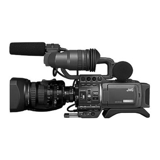
* The illustration shows the GY-HD100/GY-
HD101 HD CAMERA RECORDER with the
provided lens, viewfinder, Microphone and bat-
tery pack attached.
E
INTRODUCTION
CONTROLS,
INDICATORS AND
CONNECTORS
PREPARATIONS
PREPARATIONS
FOR OPERATION
SETTING AND
ADJUSTMENTS
BEFORE SHOOTING
SHOOTING
OPERATION
PLAYBACK MODE
USING EXTERNAL
COMPONENTS
MENU SCREENS
FEATURES OF THE
CAMERA SECTION
OTHERS
LWT0278-001A-H
Advertisement
Table of Contents

Related Manuals for JVC GY- HD101


Summary of Contents for JVC GY- HD101
- Page 1 HD CAMERA RECORDER GY-HD100 GY-HD101 Thank you for purchasing this JVC product. Before operating this unit, please read the instructions carefully to ensure the best possible performance. For Customer Use : Enter below the Serial No. which is located on the body.
- Page 3 Read all of these instructions. Keep these instructions. Heed all warnings. Follow all instructions. Do not use this apparatus near water. Clean only with dry cloth. Do not block any ventilation openings. Install in accordance with the manufacturer’s instructions. Do not install near any heat sources such as radiators, heat resisters, stoves, or other apparatus (includ- ing amplifiers) that produce heat.
- Page 4 Consult the dealer or an experienced radio/TV technician for help. CAUTION: CHANGES OR MODIFICATIONS NOT APPROVED BY JVC COULD VOID USER’S AUTHORITY TO OPERATE THE EQUIPMENT. THIS DEVICE COMPLIES WITH PART 15 OF THE FCC RULES.
-
Page 5: Caution For Ac Mains Lead
FOR EUROPE This equipment is in conformity with the provisions and protection requirements of the corresponding European Directives. This equipment is designed for professional video appliances and can be used in the following environments: residential area (in houses) commercial and light industry; e.g. offices or theatres urban outdoors In order to keep the best performance and furthermore for electro- magnetic compatibility we recommend to use cables not exceeding... -
Page 6: Accessories
• Recorded video and audio contents are for private use. Other use may infringe on the rights of copyright holders. • JVC cannot assume liabilities that may derive from the impossibility of normal recording or playback of video or audio due to malfunction of the camcorder or the video- cassette. -
Page 7: Main Features
• This camcorder records in HDV format or DV format. DV format can record and play back SD (Standard Defini- tion) video on Mini DV videocassettes. HDV format can record and play back HD (High Definition) or SD (Standard Definition) video on Mini DV videocas- settes. -
Page 8: Table Of Contents
ACCESSORIES ....... . . 2 MAIN FEATURES ....... . 3 INTRODUCTION Precautions for Proper Use . - Page 9 SHOOTING OPERATION Basic Recording Operation ......48 • If the Record-Standby Mode Continues • Checking Recorded Contents in Record-Standby Mode (Recording Check Function) HEADER REC Function .
-
Page 10: Introduction
• If you use the camcorder continuously for a long period of time, the characters displayed in the viewfinder may tem- porarily remain on the screen. This is not recorded on the tape. -
Page 11: Routine And Periodical Maintenance
Block Noise • Please use cleaning tape produced by JVC. Do not use head cleaning tapes other than specified. X See “Precautions for Use of Head Cleaning Tape”... -
Page 12: Battery Pack To Be Used
INTRODUCTION Battery Pack to be Used The GY-HD100 can use any of the following batteries. • BN-V428, BN-V438 Videocassette to be Used • Use JVC’s videocassette tapes marked with the A sym- bol. • Mini DV videocassette : M-DV63HD M-DV63PROHD * Do not use M-DV80. -
Page 13: Condensation
Condensation • If the unit has been cooled down in a cold place and is then carried to a warm place, the moisture contained in the warm air may adhere to the head drum or tape guides and be cooled into water droplets. This phenomenon is referred to as condensation (dewing). -
Page 14: Controls, Indicators And Connectors
ZOOM Lens (Optional) Th16 x 5.5BRMU 1FOCUS ring Manual focus ring. 2ZOOM lever/ring This is the manual zoom ring equipped with a zoom lever. To adjust the zoom manually, turn the zoom mode knob b to position “M”. 3IRIS ring Manual iris ring. -
Page 15: Front Section
Front Section 1Shoe Makes it possible to mount separately sold lights and accessories. 2Knob This is the mounting knob for the microphone holder 3. 3Microphone holder Makes it possible to attach the provided microphone or a separately sold microphone. X See “Attaching the Microphone (Provided)” on page 29. 4Front tally lamp This lamp lights up when the GY-HD100 enters the record mode. -
Page 16: Rear Section
CONTROLS, INDICATORS AND CONNECTORS Rear Section 1Back tally lamp This lamp lights up when the GY-HD100 enters the record mode. It blinks during the transition to the record mode. When the tape has run out, or the VTR enters the warning mode, it blinks quickly. -
Page 17: Lcd Door
LCD Door 1[LCD BRIGHT +/–] LCD brightness +/– button This button is for adjusting the brightness of the LCD moni- tor display. • Pushing the button in the + direction makes the monitor brighter. • Pushing the button in the – direction makes the monitor darker. -
Page 18: Right Side Section
CONTROLS, INDICATORS AND CONNECTORS Right Side Section VF BRIGHT USER 1 USER 2 USER 3 ND FILTER MENU STATUS WHT.BAL AUTO AUTO AUDIO LEVEL CH-1 CH-2 POWER 1Monitoring speaker (Ear pad) • In the Camera mode, the input sound can be EE moni- tored. - Page 19 When attaching the lens, slide the stand forward. CAUTION There is a risk that the camcorder will fall onto the viewfinder side when the lens is not attached, so leave the lens attached even if you are not using it.
-
Page 20: Left Side Section
CONTROLS, INDICATORS AND CONNECTORS Left Side Section 2 3 4 5 1[DC INPUT] DC connector Power input for 7.2 V DC accepts the supplied AC adapter. X See “AC Operation” on page 31. 2[LINE OUTPUT] Line output connector (Φ3.5mm) Output connector for audio signals. •... -
Page 21: Top Section
X See “Inserting an SD Memory Card” on page 30. When an SD memory card is loaded • You can save, call up and reset the menu settings on this camcorder. • You can initialize (format) an SD memory card. X See “FILE MANAGE Menu Screen” on page 79. - Page 22 CONTROLS, INDICATORS AND CONNECTORS Top Section (Cont’d) e[MONITOR SELECT] Audio monitor selector switch This switch is used to select the monitor sound output and playback sound output from the monitoring speaker 1 on page 14 or the PHONES jack 2 on page 12. CH-1 : The CH-1 channel audio is output.
-
Page 23: Indications On The Lcd Monitor And In The Viewfinder
Indications on the LCD Monitor and in the Viewfinder DISPLAY button USER 1 USER 2 USER 3 SHUTTER ND FILTER MENU STATUS WHT.BAL AUTO AUTO STATUS button • CAMERA MODE (display example) STATUS 0 STATUS 4 • VTR MODE (display example) STATUS 3 CONTROLS, INDICATORS AND CONNECTORS In addition to showing the EE image and the playback picture,... -
Page 24: Status Screens In The Camera Mode
CONTROLS, INDICATORS AND CONNECTORS Indications on the LCD Monitor and in the Viewfinder (Cont’d) Status Screens in the Camera Mode STATUS 0 Screen • STATUS 0 1 Event Indication When the Gain or Shutter Speed is changed manually, the setting condition is displayed for about 3 seconds at the time the change is made. - Page 25 Item VTR mode indication STBY : In record standby mode (record-pause mode) PLAY : During playback STOP : Stop mode (Tape protect mode) EJECT : Cassette being ejected - - - Indication of date and time Indicates the date and time. Whether or not the date and time should be displayed as well as the display style are set on the TIME/ DATE menu.
- Page 26 CONTROLS, INDICATORS AND CONNECTORS Indications on the LCD Monitor and in the Viewfinder (Cont’d) STATUS 1 Screen • STATUS 1 In addition to the information on the STATUS 0 screen, this screen displays the following items. Item VIDEO FORMAT display Time Code (TC)/User’s Bits (UB) indication Remaining tape indication...
- Page 27 Item Audio sampling frequency in- 32 K : Indicated when the AUDIO MODE item on the AUDIO/MIC menu screen is set to 32 K. (Audio is dication 48 K : Indicated when the AUDIO MODE item on the AUDIO/MIC menu screen is set to 48 K. (Audio is X See page 70.
- Page 28 CONTROLS, INDICATORS AND CONNECTORS Indications on the LCD Monitor and in the Viewfinder (Cont’d) STATUS 2 Screen • STATUS 2 This screen displays the camera setup statuses. Event display is not available while this screen is displayed. Indication FILE FILE F CAM1 [********], CAM2 [********], and EXT1 - 4 [********] * indicates SUB NAME X See page 79–81.
-
Page 29: Status Screen In Vtr Mode
You can switch this display ON/OFF using the VIDEO FORMAT item on the LCD/VF [2/3] menu screen. X See page 72. MEMO This camcorder cannot play back or output tape recorded in HDV 1080i format. “INVALID TAPE!” is dis- played in the event display area 4. Time code (TC) and user’s bits Displays the time code data being recorded (hour, minute, second, frame) when in VTR mode. -
Page 30: Menu Setting Screen
CONTROLS, INDICATORS AND CONNECTORS Indications on the LCD Monitor and in the Viewfinder (Cont’d) TOP MENU screen (Camera mode) Alarm display area Safety Zone Indication (Camera mode only) The indication of the following safety zone and center mark indications can be turned ON/OFF with the SAFETY ZONE item and CENTER MARK item on the LCD/VF [1/3] menu screen. - Page 31 DISPLAY button, the display mode is cancelled by the LCD monitor open/close and normal/inverted oper- ations. • If the LCD monitor is closed inside the camcorder with the screen in the normal display orientation, holding down the DISPLAY button does not work.
-
Page 32: Preparations
YH16 × 7K12U (CANON) YH19 × 6.7K12U (CANON) *1 An HZ-FM13 cannot be used with a Th16×5.5BRMU or S14×7.3B12/U zoom lens. Use a FUJINON focus manual unit (FMM-8, CFH-3, CFC-12-990). For details, please consult your JVC authorized dealer. EARPHONE GY-HD100 BATTERY... -
Page 33: Attaching The Zoom Lens (Provided)
Attaching the Zoom Lens (Provided) Hole Clamp Attaching the Microphone (Provided) 1. 3. Knob INPUT1, 2 connector How to Attach the Viewfinder Knob Taking off the viewfinder Loosen the mount ring. Attach the lens with its pin aligned with the hole in the mount. -
Page 34: Inserting An Sd Memory Card
To reduce the emission of unwanted radio waves, be sure to attach the provided core filter as shown in the figure on the left. Attach the core filter (black) as close to the camcorder as possible, as shown in the figure. -
Page 35: Ac Operation
AC Operation POWER lamp DC IN AC adapter connector Ferrite core DC cable Core filter (gray) The GY-HD100 is operable with AC power supply or battery pack. Use the supplied AC adapter as the AC power supply. After making sure that the power switches of the GY- HD100 and of the AC adapter are set to OFF, connect the To plug outlet DC cable from the AC adapter to the DC IN connector of... -
Page 36: Battery Operation
PREPARATIONS Battery Operation AC outlet AC cord AC adapter CHARGE lamp 1 POWER lamp CHARGE lamp 2 Connector Charging the Battery Pack Before use the battery pack should be charged using the pro- vided AC Adapter. * Be sure to pull the DC cable out of the AC adapter when you charge the battery. -
Page 37: Remaining Battery Power Display
Remaining Battery Power Display LCD monitor/Viewfinder When the remaining battery power is nearly exhausted, the following warnings will be generated. Viewfinder screen or LCD monitor When a Status screen is displayed (excluding the STATUS 2, 3 screen in the Camera mode) •... -
Page 38: Preparations For Operation
Turning the Power ON CH-1 BOTH CH-2 MONITOR SELECT DISPLAY VTR indicator VF BRIGHT USER 1 USER 2 USER 3 SHUTTER ND FILTER MENU STATUS WHT.BAL AUTO AUTO AUDIO LEVEL CH-1 CH-2 POWER switch POWER Turning the Power ON Set the POWER switch to ON. The unit turns on in Camera mode. -
Page 39: Loading/Unloading The Cassette
“REC” side. • Remove any the tape slack before loading. Turn the POWER switch ON. Slide the EJECT switch on the top panel of the camcorder to the side. The videocassette cover opens automatically and a video- cassette tape can be inserted. -
Page 40: Setting And Displaying The Date And Time
PREPARATIONS FOR OPERATION Setting and Displaying the Date and Time USER 1 USER 2 SHUTTER dial SHUTTER ND FILTER MENU STATUS WHT.BAL STATUS button POWER POWER switch TC/UB/CLOCK menu screen TIME/DATE menu screen The date and time of the built-in clock should be set. Powered by the built-in backup battery the set date and time data con- tinue to count even when the power is switched off. -
Page 41: Setting The Date And Time
TIME/DATE menu screen CLOCK ADJUST menu screen Date Time (Hour:Min) Date Time PREPARATIONS FOR OPERATION Setting the Date and Time Display the CLOCK ADJUST menu screen. Select the CLOCK ADJUST item on the TIME/DATE menu screen. Set the date and time. The blinking digit is the one to be set. -
Page 42: Displaying Time Code
PREPARATIONS FOR OPERATION Displaying Time Code LCD/VF [2/3] menu screen TC DISPLAY switch TC GENE. switch Time code indication STATUS 1 screen The GY-HD100 records SMPTE-standard (NTSC) or EBU- standard (PAL) time codes and user’s bits. In the play mode or the record mode, the reproduced time codes or user’s bits are shown on the LCD monitor or in the viewfinder. -
Page 43: Recording Time Codes In Continuation Of Time Codes Recorded On Tape
Recording Time Codes in Continuation of Time Codes Recorded on Tape The GY-HD100 also incorporates a time code reader. There- fore, when the unit enters record mode from record-standby mode, it can read the time code data recorded on the tape and record time codes in continuation of the existing data. -
Page 44: Presetting Time Cord Data
PREPARATIONS FOR OPERATION Presetting and Recording of Time Code (Cont’d) Time code (hour, min, sec, frame) Presetting time cord data The time code and user’s bit data are preset on the TC/UB/ CLOCK menu screen. Display the TC/UB/CLOCK menu screen. Select the TC/UB/CLOCK item on the TOP MENU screen. -
Page 45: Screen Adjustment
Screen Adjustment 180° up 90° down LCD lock release lever Viewfinder Adjustment Eyepiece focusing ring VF BRIGHT volume PEAKING volume Sliding securing ring PREPARATIONS FOR OPERATION LCD monitor direction, angle, screen brightness, etc. can be adjusted. Adjusting the Direction and Angle of the PEAKING volume LCD monitor LCD BRIGHT... -
Page 46: Back Focus Adjustment
PREPARATIONS FOR OPERATION Back Focus Adjustment Siemens star chart It is only necessary to perform this when the lens is attached for the first time or when focusing is not correct in both the telephoto and wide-angle positions. • It is easier to adjust back focus when the subject is more than 3 meters from the camera. -
Page 47: White Balance Adjustment
White Balance Adjustment Iris mode switch AWB button During operation Improper object Insufficient illumination Excessive illumination CAUTION • Do not adjust using any highly reflective objects, such as metal, etc., as this may result in improper white balance adjustment. • The FAW (Full Auto White balance) function cannot pro- vide optimum white balance with a subject outside the FAW adjustment range, for example when it contains only a single color or not enough white color. -
Page 48: Setting And Adjustments Before Shooting
Setting the Video Format SHUTTER dial STATUS button Set the video format using the FRAME RATE item and the REC item on the VIDEO FORMAT menu screen. Setting the FRAME RATE Item Press the STATUS button for at least 1 second. •... -
Page 49: Camera Settings
SETTING AND ADJUSTMENTS BEFORE SHOOTING Camera Settings VTR indicator CAM/VTR button Screen Size (4:3/16:9) Mode Selection ASPECT item 16:9 Set the switch positions. A. [GAIN] switch: Set to L ( 0 dB). B. [WHT. BAL] (Auto White Balance) switch: Set to A or B. Set the lens’... -
Page 50: Audio Input Signal Selection
SETTING AND ADJUSTMENTS BEFORE SHOOTING Audio Input Signal Selection CH-2 INPUT switch AUDIO INPUT switch MONITOR SELECT FULL AUTO switch switch MONITOR volume CH-1 audio input level volume CH-2 audio input level volume STATUS 1 screen Audio level Indicator level (reference) ∞... -
Page 51: Monitoring Audio During Recording
SETTING AND ADJUSTMENTS BEFORE SHOOTING PHONES jack CAUTION • When the AUDIO INPUT switch is set to MIC, be sure to check that the microphone is connected to the INPUT1/2 connector. If the microphone is not connected, increasing the audio level could cause noise from the input connec- tor to be recorded on the tape. -
Page 52: Shooting Operation
Basic Recording Operation FRONT TALLY lamp POWER switch REC trigger button BACK TALLY lamp VTR trigger button About the QUICK REC START Mode If the REC/VTR trigger button is pressed immediately after the videocassette is inserted, the mode becomes the QUICK REC START mode that enables quick start of recording. -
Page 53: If The Record-Standby Mode Continues
DV format is played back, and about 8 sec- onds of the content recorded in HDV format is played back. After playback, the camcorder returns to standby mode at the position on the tape where the RET button was pressed. -
Page 54: Header Rec Function
SHOOTING OPERATION HEADER REC Function When the REC/VTR trigger button is pressed while the STOP button is pressed, this function first records the color bar video and the test tone (1 kHz sine-wave) of the built-in signal generator at the beginning of the tape. Then it records the black video signal and the mute audio signal for the duration specified in advance. - Page 55 TC/UB/CLOCK menu screen HEADER REC menu screen Cursor Item Set value During HEADER REC • The menu screen is not displayed during HEADER REC recording. How to set the HEADER REC menu screen Display the HEADER REC menu screen. 1Select the TC/UB/CLOCK.. item on the TOP MENU screen.
-
Page 56: Playback Mode
Playback Procedure Recorded pictures can be viewed in the viewfinder, or on the LCD monitor, or on the monitor connected to the video output connector. STOP button PLAY/STILL button REW button MEMO The GY-HD100 can play back the following two types of vid- eocassettes: •... -
Page 57: Outputting Audio
Outputting Audio MONITOR VTR indicator SELECT switch SHUTTER dial STATUS button AUDIO menu screen Table 1 PB AUDIO CH [DV] MONITOR SELECT AUDIO MONITOR CH-1 BOTH STEREO CH-2 Setting Confirm that the GY-HD100 is in the VTR mode. (VTR indicator: On) Display the AUDIO menu screen. -
Page 58: Using External Components
IEEE 1394 • Attach the clamp filter as close to the camcorder as possi- ble, as shown in the figure. • Set the IEEE1394 switch on the left panel of the cam- corder. -
Page 59: Dubbing With Av Devices
To reduce the emission of unwanted radio waves, be sure to attach the provided clamp filter as shown in the figure on the left. • Attach the clamp filter as close to the camcorder as possible, as shown in the figure. Turn both devices on. -
Page 60: Hdv/Dv Dubbing
STOP button on the camcorder, and stop the playback. MEMO • Switch the IEEE1394 switch when the camcorder is OFF. • When you dub still images, they are low resolution images. Noise may also enter the audio. - Page 61 Set the TC DUPLI. [DV] item on the TC/UB/CLOCK menu screen. (Only for DV format) Date and time data MEMO In HDV format, the TC/UB set in the camcorder is recorded regardless of the setting. Insert the videocassettes. GY-HD100 Playback unit Start playback on the playback unit.
-
Page 62: Backup Recording
USING EXTERNAL COMPONENTS Backup Recording IEEE1394 switch IEEE 1394 Master unit GY-HD100 Signal flow CAUTION • Set the IEEE1394 switch on both devices to either HDV or DV. • Start recording after making sure that both devices are properly connected. OTHERS [2/2] menu screen Backup Recording of the GY-HD100’s Camera Image and Sound Through the... -
Page 63: Menu Screens
MENU SCREENS Menu Screen Configuration The Menu Screen consists of multiple layers of menu screens as shown below. The menu screen to be set is selected from the TOP MENU in accordance with the function or purpose. The items on the menu screens differ with the Camera mode and the VTR mode. The contents of set items are stored in the GY- HD100’s memory and are retained even when the power is turned off. -
Page 64: Setting Menu Screens
MENU SCREENS Setting Menu Screens USER1 USER2 USER3 button SHUTTER dial USER 1 USER 2 SHUTTER ND FILTER MENU STATUS WHT.BAL AUTO STATUS button Cursor Menu screen TOP MENU screen Item VIDEO FORMAT menu screen Make the settings while observing the LCD monitor or the viewfinder screen. -
Page 65: Top Menu Screen
Displays the FILE MANAGE menu screen. Saves the menu screen settings as a file on the camcorder or an SD memory card, or reads the menu screen settings saved in the file. It is also possible to reset the menu settings to default settings or initialize (format) an SD memory card. -
Page 66: Video Format Menu Screen
• If you change the FRAME RATE item setting, the system is rebooted. X See page 44. • The cursor (K) does not move to this item when the camcorder is in VTR mode or is ejecting a tape. REC* Sets the video format for shooting. - Page 67 When the FRAME RATE item is set to 50/25, this item is not displayed. The setup signal may be fixed at “0.0%” depending on the menu settings on the camcorder as well as the cables connected to it. In this case, “[0.0%]” is displayed.
-
Page 68: Camera Operation Menu Screen
MENU SCREENS CAMERA OPERATION Menu Screen The CAMERA OPERATION menu screen is only displayed in the Camera mode. Item AE LEVEL For adjusting the image level when using auto iris, “ALC” or “EEI”. Increase value: Increases level. Decrease value: Decreases level. [Settings: –3, –2, - NORMAL (0) - 2, 3] ALC MAX Sets the maximum “ALC”... -
Page 69: Camera Process [1/2] Menu Screen
CAMERA PROCESS [1/2] Menu Screen The CAMERA PROCESS menu screen consists of two screens. (1/2 screen, 2/2 screen) The CAMERA PROCESS menu screen is only displayed in camera mode. Item MASTER BLACK Adjusts the pedestal level (master black) that serves as the reference black. Increase the number : Raises the pedestal level. -
Page 70: Camera Process [2/2] Menu Screen
MENU SCREENS CAMERA PROCESS [2/2] Menu Screen Item WHITE CLIP Sets the white clipping point on input video signals with a high luminance level. 108% 100% KNEE Sets whether to run the “knee” function, which compresses video signals over a certain level to render the tonality in the highlight areas, automatically or manually. -
Page 71: Advanced Process Menu Screen
[Settings: MIN (–32), –31 - NORMAL (0) - 30, MAX (31)] MEMO • You can select this when A or B is set for the [WHT.BAL] switch c on the right panel of the camcorder. X See page 15. Settings can be made for A and B individually. (When “PRESET” is set, “-----” is displayed and this cannot be selected.) -
Page 72: Color Matrix Adjust Menu Screen
MENU SCREENS COLOR MATRIX ADJUST Menu Screen Item R GAIN For manually adjusting the shading of the R axis of the color matrix (red and cyan). Increase the number : Enhances red and cyan. Decrease the number : Reduces red and cyan. [Settings: MIN (–5), –4 - NORMAL (0) - 4, MAX (5)] R ROTATION For manually adjusting the color phase of the R axis of the color matrix (red and cyan). -
Page 73: Switch Mode Menu Screen
SWITCH MODE Menu Screen The SWITCH MODE menu screen is only displayed in camera mode. Item SHUTTER Sets the fixed value (STEP) for values that can change using the SHUTTER dial on the right panel or the VARIABLE used when shooting computer monitors. STEP VARIABLE You can set the following using the REC item on the VIDEO FORMAT menu screen. -
Page 74: Audio/Mic Menu Screen
(When HDV format is set, this is fixed at 48K and “[48K]” is displayed.) * If the DV format is 12-bit, 32 kHz, up to 4 recording track channels are available. Of those, this camcorder records on the CH-1 and CH-2 channels. This camcorder is not capable of dubbing. SEARCH AUDIO [DV] Selects whether to output audio when searching a tape recorded in DV format. -
Page 75: Lcd/Vf [1/3] Menu Screen
When the cursor is in this position, press the SHUTTER dial to return to the TOP MENU screen. *1 SAFTY ZONE and CENTER MARK will not be displayed when the camcorder is in VTR mode (PLAY, STL, FWD, REV). Function/Setting (bold characters indicate initial settings) : Zebra pattern is displayed in sections with luminance levels between 60% and 70%. -
Page 76: Lcd/Vf [2/3] Menu Screen
MENU SCREENS LCD/VF [2/3] Menu Screen [1/2] screen is displayed in the VTR mode. Item VIDEO FORMAT Selects whether to display the video format in the status display on the LCD monitor or the viewfinder. (Camera mode: STATUS 1 screen, VTR mode: STATUS screen) In camera mode : Displays the video format set in the REC item on the VIDEO FORMAT menu screen. -
Page 77: Lcd/Vf [3/3] Menu Screen
LCD/VF [3/3] Menu Screen [2/2] screen is displayed in the VTR mode. Item LCD CONTRAST Adjusts the contrast of the LCD. [Settings: MIN (–5), –4 - NORMAL (0) - 4, MAX (5)] VF CONTRAST Adjusts the contrast of the viewfinder. [Settings: MIN (–5), –4 - NORMAL (0) - 4, MAX (5)] PAGE BACK Camera mode:... -
Page 78: Tc/Ub/Clock Menu Screen
Sets how to record the timecode (TC) and user’s bits (UB) during IEEE1394 input of DV format. MEMO In HDV format, the TC/UB set in the camcorder is recorded regardless of the setting. HEADER REC To make settings related to the HEADER REC function, align the cursor with this position, and then press the SHUT- TER dial. -
Page 79: Header Rec Menu Screen
HEADER REC Menu Screen The HEADER REC menu screen is used for settings related to the HEADER REC function. (X See page 50.) Item START KEY Sets whether the HEADER REC operation should be executed when the REC/VTR trigger button is pressed while the STOP button is pressed. -
Page 80: Time/Date Menu Screen
MENU SCREENS TIME/DATE Menu Screen Item DISPLAY Sets whether the date and time are shown in the status display on the LCD monitor or in the viewfinder. When a tape with time and date not recorded is played back, there will be no display of time and date even when this item is set to ON. -
Page 81: Others [1/2] Menu Screen
OTHERS [1/2] Menu Screen The OTHERS menu screen consists of two screens (1/2 screen, 2/2 screen) Item OUTPUT CHAR. Selects whether to display the menu screen or the warning display on the monitor connected to the video signal out- put connector. : On-screen-display : No on-screen-display LONG PAUSE TIME... -
Page 82: Others [2/2] Menu Screen
MEMO • The cursor (K) does not move to this item when the camcorder is in VTR mode or is ejecting a tape. • If the current menu settings and the factory settings have different FRAME RATE settings, “REBOOT!” is dis- played for 3 seconds, the camcorder automatically turns off and then turns on. -
Page 83: File Manage Menu Screen
CINEMA HD24P: Ideal setting for movie film shooting * The read-only files listed above cannot be saved or reset. • Save menu settings (Camcorder: CAM1, CAM2; SD mem- ory card: EXT1, 2, 3, 4) to files. • Load saved files. -
Page 84: Saving Settings
MENU SCREENS FILE MANAGE Menu Screen (Cont’d) 1. 2. Settable Characters Space 5. 6. Execute Flashing Error display Error Saving settings Select the STORE FILE.. item on the FILE MANAGE menu screen. Turn the SHUTTER dial, bring the cursor (K) to SELECT and press the SHUTTER dial. -
Page 85: Resetting The Menu Settings To The Factory Settings
If the current menu settings and the factory settings have different video format settings, “REBOOT!” is displayed for 3 seconds, the camcorder turns off automatically and then turns on. When this happens, the SUB NAME initial value, “[SCENE]” is displayed. -
Page 86: Features Of The Camera Section
How to Use Skin Detail SHUTTER dial USER 1 USER 2 SHUTTER ND FILTER MENU STATUS WHT.BAL AUTO STATUS button Cursor CAMERA PROCESS [2/2] menu screen ADVANCED PROCESS menu screen 3. 4. Detection area SKIN COLOR ADJUST menu screen Black and white presenta- tion... -
Page 87: Using The Skin Detail Function
FEATURES OF THE CAMERA SECTION “SD” display STATUS 0 ZEBRA switch Using the Skin Detail Function To use the skin detail function set on the SKIN COLOR ADJUST screen, select “ON” for the SKIN DETECT item on the CAMERA PROCESS [1/2] menu screen. In addition, you can use the LEVEL item to set three levels of suppression of skin color area detail enhancement in the video signal. -
Page 88: Outputting Color Bars
FEATURES OF THE CAMERA SECTION Outputting color bars USER button This camcorder can output three types of color bars, depend- ing on the camera settings. NTSC standard PAL standard FULL AUTO switch 16:9 screen To output color bars, make the following settings. -
Page 89: Warnings And Responses
In addition, if the tape or battery is low or the VTR has a problem, the tally lamp flashes (or lights) and an alarm is output from the monitor speaker or PHONES jack. MEMO This camcorder uses microcomputers. It may not operate properly if there is external static or interference. If this happens, turn the power off and then on again. Display... - Page 90 ON. However, the tape may be damaged depending on the circum- stances. Please consult the person in charge of professional video equip- ment at your nearest JVC-authorized service agent. Press the EJECT button to take out the cassette.
- Page 91 TALLY lamp Blinks when remaining battery power or tape is low. (Only in Camera mode) Blinking Pattern Remaining Battery/Tape Slow blinking • Remaining battery power is low. (once per sec.) • Remaining tape time is equivalent to less than 3 minutes. Fast blinking •...
-
Page 92: Troubleshooting
If this menu item and the tape format do not match, the tape cannot be played back. • Is the camcorder in VTR mode? (Is the VTR indicator lit?) • Is the IEEE1394 switch set correctly? • Video head may be clogged with dirt. Clean head with the special head clean- ing tape. -
Page 93: How To Display The Hour Meter
(Business users) If you wish to dispose of this product, please visit our web page www.jvc-europe.com to obtain information about the take-back of the product. [Other Countries outside the European Union] If you wish to dispose of this product, please do so in accor-... -
Page 94: Specifications
OTHERS Specifications [General] Power requirements : DC 7.2 V, W 2.3 A Power consumption : Approx. 16.5 W (in the Record mode) Dimensions : 235 (W) × 232 (H) × 341 (D) mm Mass : 3.3 d (7.3 lbs.) (including lens (Th16×5.5BRMU), viewfinder, bat- tery pack, microphone and tape) Temperature... - Page 95 Audio cable SD memory card Instruction Manual Warranty Card (USA and Canada only) For details, consult your JVC dealer. Design and specifications are subject to change without notice. EXTERNAL DIMENSIONS (unit: mm) * Design and specifications are subject to change without notice...
- Page 96 is a registered trademark owned by Victor Company of Japan, Limited is a registered trademark in Japan, the U.S.A., the U.K. and many other countries. © 2005 Victor Company of Japan, Limited Printed in Thailand LWT0278-001A-H...