JVC GY-HD250 Instructions Manual
Hd camera recorder
Hide thumbs
Also See for GY-HD250:
- Brochure & specs (12 pages) ,
- Instructions manual (117 pages) ,
- Instrucciones (58 pages)
Table of Contents
Advertisement
Quick Links
© 2006 Victor Company of Japan, Limited
HD CAMERA RECORDER
GY-HD250
GY-HD251
Thank you for purchasing this JVC product. Before operating this
device, please read the instructions carefully to ensure the best
possible performance.
For Customer Use:
Enter below the Serial No. which is located on the body.
Retain this information for future reference.
Model No.
Serial No.
LST0440-001A
E
INTRODUCTION
CONTROLS,
INDICATORS AND
CONNECTORS
PREPARATIONS
PREPARATIONS
FOR OPERATION
SETTING AND
ADJUSTMENTS
BEFORE SHOOTING
SHOOTING
OPERATION
PLAYBACK MODE
INSTRUCTIONS
USING EXTERNAL
COMPONENTS
MENU SCREENS
FEATURES OF THE
CAMERA SECTION
OTHERS
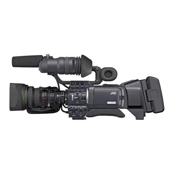
* The illustration shows the GY-HD250/GY-
HD251 HD CAMERA RECORDER with the
provided lens, viewfinder and microphone
attached.
LST0440-001A
Advertisement
Table of Contents

Related Manuals for JVC GY-HD250


Summary of Contents for JVC GY-HD250
- Page 1 © 2006 Victor Company of Japan, Limited HD CAMERA RECORDER GY-HD250 GY-HD251 Thank you for purchasing this JVC product. Before operating this device, please read the instructions carefully to ensure the best possible performance. For Customer Use: Enter below the Serial No. which is located on the body.
-
Page 2: Important Safeguards
Replace only with the same or equivalent type.” Consult the dealer or an experienced radio/TV technician for help. CAUTION: CHANGES OR MODIFICATIONS NOT APPROVED BY JVC COULD VOID USER’S AUTHORITY TO OPERATE THE EQUIPMENT. THIS DEVICE COMPLIES WITH PART 15 OF THE FCC RULES. - Page 3 (Business users) If you wish to dispose of this product, please visit our web page www.jvc-europe.com to obtain information about the take-back of the product. [Other Countries outside the European Union] If you wish to dispose of this product, please do so in accor-...
-
Page 4: Accessories
Other use may infringe on the rights of copyright hold- ers. • JVC cannot assume liabilities that may derive from the impossibility of normal recording or playback of video or audio due to malfunction of this device or the videocas- sette. -
Page 5: Table Of Contents
Charging the Built-in Battery .....36 CONTENTS Battery Operation ....... .37 Attaching the Battery. -
Page 6: Introduction
• Please use cleaning tape produced by JVC. Do not use head cleaning tapes other than specified. X See “Precautions for Use of Head Cleaning Tape”... -
Page 7: Battery Pack To Be Used
Battery Pack to be Used For recording and storing videotapes in the best con- dition The GY-HD250/GY-HD251 can use any of the following bat- teries. (Factory setting) U model: Anton Bauer battery Observe the following instructions for the best recording and storage of videotapes. -
Page 8: Controls, Indicators And Connectors
Microphone (Provided)” on page 33. 4Front tally lamp This lamp lights up when the GY-HD250/GY-HD251 enters the record mode. It blinks during the transition to the record mode. When the tape has run out, or the VTR enters the warning mode, it blinks quickly. -
Page 9: Rear Section
• Warning indications, etc. X See page 22. 1Back tally lamp This lamp lights up when the GY-HD250/GY-HD251 enters the record mode. It blinks during the transition to the record mode. When the tape has run out, or the VTR enters the warning mode, it blinks quickly. -
Page 10: Right Side Section
CONTROLS, INDICATORS AND CONNECTORS 7Clamp Right Side Section Attach the cable from the viewfinder here. 8[USER1/2/3] User buttons You can assign camera functions to the USER1 - 3 but- tons. Use them to switch shooting conditions depending upon the subject. Set them using the USER1 - 3 items in the SWITCH MODE menu screen. -
Page 11: Left Side Section
CONTROLS, INDICATORS AND CONNECTORS 4[INPUT1/INPUT2] INPUT1/INPUT2 audio input connec- Left Side Section tors These are audio input connectors for connecting to an external audio device or microphone. • Set the [AUDIO INPUT] switch 3 according to the device to be connected. •... -
Page 12: Top Section
X See “Inserting an SD Memory Card” on page 34. When an SD memory card is loaded • You can save, call up and reset the menu settings on GY-HD250/GY-HD251. • You can initialize (format) an SD memory card. X See “FILE MANAGE Menu Screen” on page 100. -
Page 13: Recording And Image Output Formats
CONTROLS, INDICATORS AND CONNECTORS Recording and Image Out- put Formats This device supports HDV and DV image formats, as well as images input from external devices. This device also has various output terminals. (Composite, analog component, HD/SD-SDI, IEEE1394) Select analog component, RGB or Y/C signals for images from the Y/P terminal in DV format. -
Page 14: Indications On The Lcd Monitor And In The Viewfinder
CONTROLS, INDICATORS AND CONNECTORS The contents of the status display are divided into those for Indications on the LCD the Camera mode and those for the VTR mode. • Each time the STATUS button is pressed in the Camera Monitor and in the View- mode, one of 5 status screens is displayed. - Page 15 CONTROLS, INDICATORS AND CONNECTORS Indications on the LCD Monitor and in the Viewfinder (Cont’d) Setting Status Contents of Indications FF/REW button was pressed in CAMERA SWITCH TO VTR MODE mode REC/VTR trigger button was pressed when 1080I REC INVALID 1080I CAMERA in the VIDEO FORMAT[1/2] menu screen was set to ON X See “FILE MANAGE Menu Screen”...
- Page 16 CONTROLS, INDICATORS AND CONNECTORS Indications on the LCD Monitor and in the Viewfinder (Cont’d) Item Contents Audio sampling frequency in- 32 K : Indicated when the AUDIO MODE item on the AUDIO/MIC[1/2] menu screen is set to 32 K. (Audio dication is recorded with 12-bit, 32 kHz sampling.) 48 K : Indicated when the AUDIO MODE item on the AUDIO/MIC[1/2] menu screen is set to 48 K.
-
Page 17: Status Screen In Vtr Mode
CONTROLS, INDICATORS AND CONNECTORS Indications on the LCD Monitor and in the Viewfinder (Cont’d) Status Screen in VTR MODE Item Contents VIDEO FORMAT display Displays the video format recorded on the tape when in VTR mode. Also displays the video format of the HDV/DV input signal. -
Page 18: Auto White Balance Indication (Camera Mode Only)
CONTROLS, INDICATORS AND CONNECTORS Indications on the LCD Monitor Alarm Message Display and in the Viewfinder (Cont’d) • The following alarm messages are displayed while the STA- TUS (0, 1, 4) screen is shown in the Camera mode, or a STA- TUS screen is shown in the VTR mode. -
Page 19: Preparations
• Be sure to tighten the mount ring completely. Incomplete Non-linear Editing System tightening may result in the lens dropping off or disturbed back focus. • Set the GY-HD250/GY-HD251’s power switch to “OFF” IDX (Endura) Battery Charger before the zoom lens is attached or detached. -
Page 20: Inserting An Sd Memory Card
About SD Memory Cards Inserting an SD Memory • When you use an SD memory card that was either just Card purchased or formatted on a device other than GY-HD250/ GY-HD251, format it on GY-HD250/GY-HD251. X See page 102. Recommended SD memory cards... -
Page 21: Ac Operation
The built-in battery is constantly being charge whenever the The GY-HD250/GY-HD251 is operable with AC power supply GY-HD250/GY-HD251 is connected to a power supply, but it or battery pack. gradually discharges while the GY-HD250/GY-HD251 is dis- Use the AC adapter as the AC power supply. -
Page 22: Precautions For The Battery Operation
ON again. • Operating time is reduced when the power zoom lens and • If the GY-HD250/GY-HD251 is left with the battery pack LCD are used frequently. attached, a small amount of power is consumed even if the POWER switch on the GY-HD250/GY-HD251 is set to OFF. -
Page 23: Loading/Unloading The Cassette
PREPARATIONS FOR OPERATION Loading/Unloading the Unloading the Cassette Cassette Turn the POWER switch to ON. When this device is in shooting standby mode or stop mode, slide the EJECT switch to the side and wait until the videocassette cover opens completely. Cassette Loading •... -
Page 24: Setting The Date And Time
EXIT item on the TOP MENU screen before pressing the SHUTTER dial. Displaying Time Code GY-HD250/GY-HD251 (NTSC) or EBU-standard (PAL) time codes and user’s bits. In the play mode or the record mode, the reproduced time codes or user’s bits are shown on the LCD monitor or in the viewfinder. -
Page 25: Presetting And Recording Of Time Code
PREPARATIONS FOR OPERATION TC/UB/CLOCK menu screen (FRAME RATE: 60/30) Presetting and Recording Use the DROP FRAME item to select the framing mode for the time code generator. of Time Code DROP The time codes from the internal time code generator can be recorded at the time of recording scenes. -
Page 26: Presetting The Time Code From The Lcd Screen
Recording Time Codes in Continuation of Time Codes Recorded on Tape The GY-HD250/GY-HD251 also incorporates a time code reader. Therefore, when this device enters record mode from record-standby mode, it can read the time code data Blink recorded on the tape and record time codes in continuation of the existing data. -
Page 27: Synchronizing With The Time Code Of The Ieee1394 (Dv)-Connected Master Unit
PREPARATIONS FOR OPERATION Synchronizing with the Time Code of the IEEE1394 (DV)-Connected Master Unit You can synchronize the time code when performing multi-camera recording. The internal time code generator will be synchro- nized with the time code in the signal input from the IEEE1394 terminal. After synchronization (slave lock), the internal time code generator continues to run even if the IEEE1394 cable is disconnected. -
Page 28: Screen Adjustment
PREPARATIONS FOR OPERATION Screen Adjustment Viewfinder Adjustment Direction of the Viewfinder LCD monitor direction, angle, screen brightness, etc. can be adjusted. Adjust the position and angle of the viewfinder. Diopter Adjustment Adjusting the Direction and Angle of the Rotate the eyepiece focusing ring until the viewfinder screen LCD monitor image is clearly visible. -
Page 29: White Balance Adjustment
PREPARATIONS FOR OPERATION • ERROR: LOW LIGHT (Insufficient illumination) White Balance Adjustment Displayed when the illumination is dim. Increase the illumi- nation and then re-adjust the white balance. • ERROR: OVER LIGHT (Excessive illumination) Displayed when the light is excessively bright. Decrease the illumination and then re-adjust the white balance. -
Page 30: Setting And Adjustments Before Shooting
SETTING AND ADJUSTMENTS BEFORE SHOOTING Turn the SHUTTER dial, change the setting and push the Setting the Video Format SHUTTER dial. • The setting stops flashing and is temporarily set. • Move the cursor (K) to the EXECUTE item and EXE- CUTE flashes. -
Page 31: Audio Input Signal Selection
INPUT1, 2 MIC REF. item on the AUDIO/MIC[1/2] tion menu screen. The GY-HD250/GY-HD251 is provided with the INPUT1 con- Adjusting Audio during Recording nector and the INPUT2 connector for audio input. Select the audio from the INPUT1 connector or the INPUT2... -
Page 32: Shooting Operation
POWER switch is moved immedi- FRONT TALLY lamp FOCUS ASSIST button ately after the trigger button is pressed, the GY-HD250/ GY-HD251 may not enter the record mode. To remedy this condition set the POWER switch to OFF and wait for 5 seconds or more before turning the power on again. -
Page 33: Header Rec Function
SHOOTING OPERATION HEADER REC Function When the REC/VTR trigger button is pressed while the STOP button is pressed, this function first records the color bar video and the test tone (1 kHz sine-wave) of the built-in signal generator at the beginning of the tape. Then it records the black video signal and the mute audio signal for the duration specified in advance. -
Page 34: Playback Mode
• Block noise may appear in the picture or the image may • Noise may appear in the picture in the still mode. freeze during the search. Outputting Audio Setting Confirm that the GY-HD250/GY-HD251 is in the VTR mode. (VTR indicator: On) : LCD/VF[1/2] menu screen MONITOR VTR indicator... -
Page 35: Using External Components
USING EXTERNAL COMPONENTS Displaying Alarms Connecting the Video • CHANGE 1394 SWITCH Displayed when the setting for the input/output video format Signal Cables from the IEEE1394 connector and the setting for the IEEE1394 switch are different. Set the IEEE1394 switch so it matches the video format. Connecting the IEEE1394 Cable To reduce the emission of unwanted radio waves, be sure to attach the provided clamp filter as shown in the figure below. -
Page 36: Using Genlock Functions
Dubbing with AV Devices Input sync signal Video signal Tri-sync By connecting the video signal output terminal and the 720p 1080i AUDIO OUTPUT terminal on GY-HD250/GY-HD251 to an AV Composite SC,H,V,F device, analog signal dubbing is possible. SD Component H,V,F Connect the cables. -
Page 37: Hdv/Dv Dubbing
When Using the GY-HD250/GY-HD251 as Recording Unit (Dubbing From Another Videocassette) Set the IEEE1394 switch on left side of the GY-HD250/ VIDEO FORMAT menu screen GY-HD251. : When dubbing in DV format HDV : When dubbing in HDV format Connect the units with the IEEE1394 cable. -
Page 38: Backup Recording
• If the backup device is equipped with a feature to record Master unit (GY-HD250/GY-HD251) time codes input from the IEEE1394 connector (TC Set the IEEE1394 switch on left side of the GY-HD250/ DUPLICATE feature), time code data the same as on the GY-HD251. -
Page 39: Menu Screen Configuration
The items on the menu screens differ with the Camera mode and the VTR mode. The contents of set items are stored in the GY- HD250/GY-HD251’s memory and are retained even when the power is turned off. The FILE MANAGE menu screen can be used to store the menu setting contents on the GY-HD250/GY-HD251 or SD memory card. Camera Mode... -
Page 40: Setting Menu Screens
Set the POWER switch to ON. Set the mode of the GY-HD250/GY-HD251 with the CAM/ VTR button. (Camera mode or VTR mode) Press the STATUS button for 1 second or longer. -
Page 41: Top Menu Screen
TOP MENU Screen Different menu screens are displayed depending on whether the GY-HD250/GY-HD251 is in the Camera mode or in the VTR mode. In the VTR mode, the CAMERA OPERATION, CAMERA PROCESS and SWITCH MODE menu screens are not dis- played. -
Page 42: Video Format[1/2] Menu Screen
MENU SCREENS VIDEO FORMAT[1/2] Menu Screen (Cont’d) * This is not displayed in VTR mode. Item Function/Setting (bold characters indicate initial settings) ASPECT* Sets the screen size for the recording video signal. (Can only be displayed and set in camera mode) : Outputs the video with an aspect ratio of 4:3. -
Page 43: Camera Operation Menu Screen
MENU SCREENS CAMERA OPERATION Menu Screen The CAMERA OPERATION menu screen is only displayed in the Camera mode. Item Function/Setting (bold characters indicate initial settings) For adjusting the image level when using auto iris, “ALC” or “EEI”. AE LEVEL Increase value : Increases level. Decrease value : Decreases level. -
Page 44: Camera Process[2/2] Menu Screen
MENU SCREENS CAMERA PROCESS[2/2] Menu Screen Item Function/Setting (bold characters indicate initial settings) BLACK Changes the gain in dark areas. Change this depending on the video signal being shot. NORMAL : Normal status STRETCH : Enhances the dark areas of the video so the contrast between light and dark is more visible by stretching the signal only in the dark areas. -
Page 45: Color Matrix Adjust Menu Screen
MENU SCREENS COLOR MATRIX ADJUST Menu Screen Item Function/Setting (bold characters indicate initial settings) R GAIN For manually adjusting the shading of the R axis of the color matrix (red and cyan). Increase the number : Enhances red and cyan. Decrease the number : Reduces red and cyan. -
Page 46: Switch Mode Menu Screen
: Digitally records with a 16-bit, 48 kHz sampling frequency. * If the DV format is 12-bit, 32 kHz, up to 4 recording track channels are available. Of those, GY-HD250/GY-HD251 records on the CH-1 and CH-2 channels. GY-HD250/GY-HD251 is not capable of dubbing. -
Page 47: Audio/Mic[2/2] Menu Screen
: Outputs the CH-3 and CH-4 channel audio. MEMO GY-HD250/GY-HD251 does not have a function for dubbing to the CH-3 and CH-4 channels. PAGE BACK When the cursor is in this position, press the SHUTTER dial to the AUDIO/MIC[1/2] menu screen. -
Page 48: Lcd/Vf[2/4] Menu Screen
MENU SCREENS LCD/VF[2/4] Menu Screen The LCD/VF[2/4] menu screen can only be set in camera mode. Item Function/Setting (bold characters indicate initial settings) LCD MIRROR MODE Sets the image display method when the LCD monitor is in counterview position. NORMAL : Image is displayed without inverting. -
Page 49: Lcd/Vf[4/4] Menu Screen
MENU SCREENS LCD/VF[4/4] Menu Screen [2/2] screen is displayed in the VTR mode. * This is not displayed in VTR mode. Item Function/Setting (bold characters indicate initial settings) LCD+VF Selects the LCD monitor and viewfinder display switching method. : Turns off the viewfinder display when the LCD monitor is opened. : Viewfinder always displayed the image. -
Page 50: Header Rec Menu Screen
MENU SCREENS HEADER REC Menu Screen The HEADER REC menu screen is used for settings related to the HEADER REC function. X See page 60. Item Function/Setting (bold characters indicate initial settings) START KEY Sets whether the HEADER REC operation should be executed when the REC/VTR trigger button is pressed while the STOP button is pressed. -
Page 51: Others[1/2] Menu Screen
Sets how to control the REC trigger command output from the IEEE1394 connector. (Can be displayed and set in camera mode) Set this when recording a backup of the HDV/DV signal from GY-HD250/GY-HD251 onto another device. : Does not control the backup device. -
Page 52: Genlock Menu Screen
MENU SCREENS OTHERS[2/2] Menu Screen (Cont’d) * This is not displayed in VTR mode. Item Function/Setting (bold characters indicate initial settings) DR-HD100 A.OFF* Selects whether or not to turn OFF the DR-HD100 (HDD unit by FOCUS enhancements) when this device is turned OFF. -
Page 53: File Manage Menu Screen
MENU SCREENS FILE MANAGE Menu Displaying the FILE MANAGE menu screen Screen Select the FILE MANAGE.. item on the TOP MENU screen. You can perform the following operations in the FILE MAN- AGE menu screen. • Settings corresponding to shooting conditions can be read Loading a menu settings file immediately with the following read-only files. -
Page 54: Resetting The Menu Settings To The Factory Settings
MENU SCREENS MEMO FILE MANAGE Menu Screen Even if CAM1, CAM2, CAM3, or CAM4 are reset, the cur- (Cont’d) rent settings are not reset. To reset the currently set values, select “CURRENT”. Initializing (formatting) an SD mem- Resetting the menu settings to the ory card factory settings Before initializing (formatting) a card:... -
Page 55: Outputting Color Bars
CESS menu screen is set to “OFF”, only the portion the skin detail function is working is displayed in skin color. X See page 83. Outputting Color Bars GY-HD250/GY-HD251 can output three types of color bars, depending on the camera settings. NTSC standard : Outputs color bars compliant with the SMPTE standard. -
Page 56: Others
In addition, if the tape or battery is low or the VTR has a problem, the tally lamp flashes (or lights) and an alarm is output from the monitor speaker or PHONES jack. MEMO GY-HD250/GY-HD251 uses microcomputers. It may not operate properly if there is external static or interference. If this hap- pens, turn the power off and then on again. Display... - Page 57 ON. However, the tape may be damaged depending on the circum- stances. Please consult the person in charge of professional video equip- ment at your nearest JVC-authorized service agent. Press the EJECT button to take out the cassette.
-
Page 58: Troubleshooting
The drum and fan motor usage times are displayed in the Remedy DRUM HOUR item and the FAN HOUR items on the OTH- ERS[2/2] menu screen as the hour meters on GY-HD250/ GY-HD251. Use as an estimate for regular maintenance. X See page 7. -
Page 59: Specifications
: 16-bit (locked audio), 48 kHz PCM (USA and Canada only) for 2 channels or 12-bit, 32 kHz PCM for 4 channels For details, consult your JVC dealer. : MiniDV tape : 18.8 mm/sec. : 63 minutes (with an M-... - Page 60 Correction About provided clamp filter Wrong Correct Earphone Conncting the Earphone Cable ●...