
Related Manuals for Toro 74637


Summary of Contents for Toro 74637
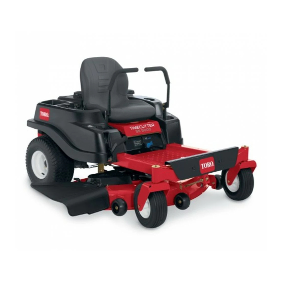
- Page 1 Form No. 3385-338 Rev A TimeCutter ® SS 5000 Riding Mower Model No. 74637—Serial No. 314000001 and Up *3385-338* A Register at www.Toro.com. Original Instructions (EN)
-
Page 2: Introduction
You are responsible for operating the product properly and safely. WARNING You may contact Toro directly at www.Toro.com for product and accessory information, help finding a dealer, or to register CALIFORNIA your product. -
Page 3: Table Of Contents
Contents Schematics ..............44 Introduction ..............2 Safety ................4 Safe Operating Practices........... 4 Safety and Instructional Decals ......... 6 Product Overview ............10 Controls ...............10 Operation ..............11 Adding Fuel............11 Checking the Engine-oil Level........13 Breaking in a New Machine........13 Think Safety First ...........13 Starting the Engine ..........14 Operating the Blades..........15 Testing the Safety-interlock System ......16... -
Page 4: Safety
In these instances, is seen or thunder is heard in the area, do not operate Toro has refined the statement to convey the meaning of the the machine; seek shelter. standard while better matching the product this Operator's Manual pertains. -
Page 5: Safe Handling Of Gasoline
• Always keep the drive wheels engaged when going down machine, operator, and ballast. Use counterweights or slopes. wheel weights as described in the attachment, or in the pulling machine Operator’s Manual. • Reduce speed and use extreme caution on slopes. •... -
Page 6: Safety And Instructional Decals
Frequently check components • Use only genuine Toro replacement parts to ensure that and replace with manufacturers' recommended parts, original standards are maintained. when necessary. •... - Page 7 119-8815 1. Parking position 4. Neutral 2. Fast 5. Reverse 3. Slow 119-8870 50-inch Model 1. Height-of-cut 121-2989 1. Bypass lever position for 2. Bypass lever position for pushing the machine operating the machine 112-9840 1. Read the Operator's 3. Remove the ignition key Manual.
- Page 8 120-2239 1. Warning—read the Operator's Manual. 5. Warning—do not use split ramps, use a full ramps when transporting machine. 2. Warning—read the instructions before servicing or performing 6. Loss of traction/control hazard, slopes—loss of traction/control maintenance; move the motion control levers to the park on a slope, disengage the blade control switch (PTO), (brake) position, remove the ignition key and disconnect the proceed off the slope slowly.
- Page 9 121-0773 1. Fast 4. Choke 2. Continuous variable setting 5. Power take-off (PTO), Blade control switch 3. Slow...
-
Page 10: Product Overview
Product Overview Figure 3 1. Deflector 4. Height-of-cut lever 7. Footrest 10. Control panel 2. Rear drive wheel 5. Operator seat 8. Engine 11. Engine guard 3. Motion-control levers 6. Smart Speed™ lever 9. Fuel-tank cap 12. Front caster wheel Controls Ignition Switch The ignition switch has 3 positions: Off, Run, and Start. -
Page 11: Operation
Operation reverse; wheel speed is proportional to the amount the lever is moved. Move the control levers outward from the center to the park position, and exit the machine (Figure 16). Always Note: Determine the left and right sides of the machine position the motion-control levers into the park position from the normal operating position. -
Page 12: Filling The Fuel Tank
of varnish deposits in the fuel system, use fuel stabilizer DANGER at all times. In certain conditions during fueling, static electricity can be released causing a spark which Filling the Fuel Tank can ignite the gasoline vapors. A fire or explosion Ensure that the engine is shut off and the motion controls are from gasoline can burn you and others and can in the parked position. -
Page 13: Checking The Engine-Oil Level
3. Install the fuel-tank cap securely, and tighten until it clicks. Checking the Engine-oil Level Before you start the engine and use the machine, check the oil level in the engine crankcase; refer to Checking the Engine-oil Level (page 24). Breaking in a New Machine New engines take time to develop full power. -
Page 14: Starting The Engine
Understanding the Safety-interlock System WARNING If safety-interlock switches are disconnected or damaged, the machine could operate unexpectedly causing personal injury. • Do not tamper with the interlock switches. • Check the operation of the interlock switches daily, and replace any damaged switches before operating the machine. -
Page 15: Operating The Blades
Figure 14 1. Control panel 2. Blade-control switch—On position Figure 13 1. Control panel 5. Run 2. Ignition key—run position 6. Start Disengaging the Blades 3. Ignition key—start position 7. Choke control 4. Off Push down on the blade-control switch to move it to the Off position, and disengage the blades (Figure 15). -
Page 16: Testing The Safety-Interlock System
Testing the Safety-interlock Driving System Driving the machine benefits from an understanding of what zero-turn-radius mower means. The drive wheels turn Test the safety-interlock system before you use the machine independently, powered by hydraulic motors on each axle; each time. If the safety system does not operate as described hence one side can turn in reverse while the other turns below, have an Authorized Service Dealer repair the safety forward causing the machine to spin rather than turn. -
Page 17: Driving Forward
Using the Smart Speed™ Control Driving Forward System 1. Move the levers to the center, unlocked position. The Smart Speed™ Control-System lever, located below the 2. To go forward, slowly push the motion-control levers operating position (Figure 17), gives the operator a choice to forward (Figure 16). -
Page 18: Stopping The Machine
Driving Backward Adjusting the Height-of-Cut 1. Move the levers to the center, unlocked position. Height-of-cut is controlled by the lever located to the right of the operating position (Figure 20). 2. To go backward, look behind you and down, as you slowly pull the motion-control levers rearward (Figure 1. -
Page 19: Positioning The Seat
Adjusting the Motion-control Levers Adjusting the Height G010233 The motion-control levers can be adjusted higher or lower for maximum operator comfort. 1. Remove the 2 bolts holding the control lever to the control-arm shaft (Figure 23). 2. Move the control lever to the next set of holes. Figure 21 3. -
Page 20: Operating The Machine
Pushing the Machine 1. Park the machine on a level surface, and disengage the blade-control switch. 2. Move the motion-control levers outward to the park position, stop the engine, and wait for all moving parts to stop before leaving the operating position. 3. -
Page 21: Operating Tips
If a blade is damaged or worn, replace it immediately with a genuine Toro replacement blade. Cutting 1/3 of the Grass Blade It is best to cut only about 1/3 of the grass blade. Cutting more than that is not recommended unless grass is sparse, or it is late fall when grass grows more slowly. -
Page 22: Maintenance
Maintenance Note: Determine the left and right sides of the machine from the normal operating position. Recommended Maintenance Schedule(s) Maintenance Service Maintenance Procedure Interval • Check the safety-interlock system. • Check the air cleaner for dirty, loose or damaged parts. •... -
Page 23: Premaintenance Procedures
Premaintenance Lubrication Procedures Greasing the Bearings Service Interval: Every 25 hours—Grease all the lubrication Raising the Seat points. Make sure that the motion-control levers are locked in the Grease Type: No. 2 general purpose, lithium-base grease park position. Lift the seat forward. 1. -
Page 24: Engine Maintenance
Engine Maintenance Servicing the Air Cleaner Service Interval: Before each use or daily—Check the air cleaner for dirty, loose or damaged parts. Every 50 hours—Service the paper element (more often under extremely dusty, dirty conditions). Every 100 hours—Replace the paper element (more often under extremely dusty, dirty conditions). - Page 25 Changing the Engine Oil and the 5. Insert the dipstick into the tube. Engine-oil Filter Service Interval: Every 100 hours—Change the engine oil and the engine-oil filter. Fill with oil as specified in the “Viscosity Grades” table (Figure 28). Change the engine oil and the engine-oil filter while the engine is still warm.
-
Page 26: Servicing The Spark Plug
Servicing the Spark Plug 10. Locate the oil filter on the right side of the engine, and remove the old filter and wipe off the filter adapter Service Interval: Every 200 hours—Check spark plug(s) with a clean cloth (Figure 31). condition and gap. -
Page 27: Cleaning The Blower Housing
Fuel System Maintenance DANGER In certain conditions, gasoline is extremely flammable and highly explosive. A fire or explosion G008794 from gasoline can burn you and others and can Figure 33 damage property. • Perform any fuel related maintenance when the engine is cold. -
Page 28: Electrical System Maintenance
Electrical System 4. Squeeze the ends of the hose clamps together and slide them away from the filter (Figure 34). Maintenance 5. Remove the filter from the fuel lines. 6. Install a new filter with the flow-direction arrow WARNING coming from the fuel tank and pointing to the engine. 7. -
Page 29: Installing The Battery
Charging the Battery WARNING Service Interval: Before storage—Charge the battery and Incorrect battery-cable routing could damage disconnect battery cables. the machine and cables causing sparks. Sparks can cause the battery gasses to 1. Remove the battery from the chassis; refer to Removing explode, resulting in personal injury. -
Page 30: Servicing The Fuses
Servicing the Fuses Drive System Maintenance The electrical system is protected by fuses. It requires no maintenance; however, if a fuse blows, check the component/circuit for a malfunction or short. Checking the Tire Pressure Fuse type: • Main—F1-30 amp, blade-type Service Interval: Every 25 hours—Check tire pressure. -
Page 31: Releasing The Electric Brake
File down any nicks and sharpen the blades as necessary. If a blade is damaged or worn, replace it immediately with a genuine Toro replacement blade. For convenient sharpening and replacement, you may want to keep extra blades on hand. - Page 32 3. Measure from the tip of the blade to the flat surface (Figure 42). Figure 40 1. Cutting edge 3. Wear/slot forming G014973 2. Curved area 4. Damage Figure 42 Checking for Bent Blades 1. Blade (in position for measuring) Note: The machine must be on a level surface for the 2.
-
Page 33: Removing The Blades
To ensure balancer (Figure 47). optimum performance and continued safety conformance of the machine, use genuine Toro replacement blades. Note: If the blade stays in a horizontal position, the Replacement blades made by other manufacturers may result blade is balanced, and can be used. -
Page 34: Leveling The Mower Deck
G005278 2. Install the blade stiffener, the curved washer (cupped side toward the blade), and the blade bolt (Figure 45). 3. Torque the blade bolt to 47 to 88 N-m (35 to 65 ft-lb). Leveling the Mower Deck Check to ensure that the mower deck is level any time you install the mower or when you see an uneven cut on your lawn. -
Page 35: Adjusting The Front-To-Rear Blade Slope
G015323 G015325 Figure 52 1. 0.25 inch 2. 0.125 inch Figure 50 1. Hanger bracket 4. Side locking nut. 12. Stop the deck at the adjusted position and tighten the 2. Slotted adjustment 5. Side carriage bolt side locking nut on the hanger bracket to hold the new position position (Figure 51). -
Page 36: Removing The Mower
G009658 Figure 53 Mower decks with 2 blades 1. Blades front to rear 2. Measure from the tip of the blade to the flat surface here. G014634 Figure 55 1. Adjusting rod 3. Locknut 2. Adjusting block 7. To raise the front of the mower, tighten the adjustment nut. -
Page 37: Installing The Mower
Note: Retain all parts for future installation. Installing the Mower 1. Park the machine on a level surface and disengage the blade-control switch. 2. Move the motion-control levers outward to the park position, stop the engine, remove the key, and wait for all moving parts to stop before leaving the operating position. -
Page 38: Mower Belt Maintenance
3. Set the height-of-cut at the lowest cutting position [38 mm (1-1/2 inches)]. 3. Remove the damaged or worn grass deflector. 4. Using a spring-removal tool, (Toro part no. 92-5771), 4. Replace the grass deflector (Figure 58). remove the idler spring from the deck hook to remove 5. - Page 39 6. Using a spring-removal tool, (Toro part no. 92-5771), install the idler spring over the deck hook and placing tension on the idler pulley and mower belt (Figure 59 and Figure 60). G014930 Figure 59 Mower Decks with 2 Blades 1.
-
Page 40: Cleaning
Cleaning Note: If the mower is not clean after one washing, soak it and let it stand for 30 minutes. Then, repeat the process. Washing the Underside of the 9. Run the mower again for 1 to 3 minutes to remove excess water. -
Page 41: Storage
Storage plug(s) removed from the engine, pour 2 tablespoons of engine oil into the spark plug hole. Use the starter to crank the engine and distribute the oil inside the Cleaning and Storage cylinder. Install the spark plug(s). Do not install the wire on the spark plug(s). -
Page 42: Troubleshooting
Troubleshooting Problem Possible Cause Corrective Action The engine overheats. 1. The engine load is excessive. 1. Reduce the ground speed. 2. The oil level in the crankcase is low. 2. Add oil to the crankcase. 3. The cooling fins and air passages 3. - Page 43 Problem Possible Cause Corrective Action There is an abnormal vibration. 1. The engine-mounting bolts are loose. 1. Tighten the engine-mounting bolts. 2. The engine pulley, idler pulley, or blade 2. Tighten the appropriate pulley. pulley is loose. 3. The engine pulley is damaged. 3.
- Page 44 Schematics G014644 Electrical Diagram (Rev. A)
- Page 45 Notes:...
- Page 46 Notes:...
- Page 47 Notes:...
- Page 48 Toro importer. If all other remedies fail, you may contact us at Toro Warranty Company. Australian Consumer Law: Australian customers will find details relating to the Australian Consumer Law either inside the box or at your local Toro Dealer.