Table of Contents
Advertisement
Advertisement
Table of Contents

Related Manuals for MSI KT4 Ultra


Summary of Contents for MSI KT4 Ultra
- Page 1 KT4 Ultra MS-6590 (v1.X) ATX Mainboard Version 1.2 G52-M6590X8...
-
Page 2: Fcc-B Radio Frequency Interference Statement
Manual Rev: 1.2 Release Date: November 2002 FCC-B Radio Frequency Interference Statement This equipment has been tested and found to comply with the limits for a class B digital device, pursuant to part 15 of the FCC rules. These limits are designed to provide reasonable protection against harmful interference when the equip- ment is operated in a commercial environment. -
Page 3: Copyright Notice
Alternatively, please try the following help resources for further guidance. Visit the MSI website for FAQ, technical guide, BIOS updates, driver updates, and other information: http://www.msi.com.tw/ Contact our technical staff at: support@msi.com.tw... -
Page 4: Safety Instructions
Safety Instructions Always read the safety instructions carefully. Keep this User’s Manual for future reference. Keep this equipment away from humidity. Lay this equipment on a reliable flat surface before setting it up. The openings on the enclosure are for air convection hence protects the equipment from overheating. -
Page 5: Table Of Contents
Live BIOS™/Live Driver™ ... 1-7 Live Monitor™ ... 1-7 D-Bracket™ 2 (Optional) ... 1-9 S-Bracket (Optional) ... 1-10 MSI DVD (5.1 Channel) ... 1-12 CPU Thermal Protection ... 1-14 Chapter 2. Hardware Setup ... 2-1 Quick Components Guide ... 2-3 Central Processing Unit: CPU ... - Page 6 Mouse Connector ... 2-9 RJ-45 LAN Jack (Optional) ... 2-10 Keyboard Connector ... 2-11 USB 2.0 Connectors ... 2-11 Serial Port Connectors: COM A & COM B ... 2-11 Parallel Port Connector: LPT1 ... 2-13 Audio Port Connectors ... 2-13 Connectors ...
- Page 7 Entering Setup ... 3-3 Selecting the First Boot Device ... 3-3 Control Keys ... 3-3 Getting Help ... 3-3 The Main Menu ... 3-5 Standard CMOS Features ... 3-7 Advanced BIOS Features ... 3-9 Advanced Chipset Features ... 3-13 Power Management Features ... 3-19 PNP/PCI Configurations ...
-
Page 8: Chapter 1. Getting Started
SPDIF pinheader for digital audio transmission, and one extra Bluetooth pinheader that fulfills your need for wireless connection. Designed to fit the advanced AMD Athlon™ XP or Duron™ processors, the KT4 Ultra delivers a high performance and professional desktop platform solution. Getting Started Apollo KT400 ®... -
Page 9: Mainboard Specifications
Supports six memory banks using three 184-pin 200/266/333/400 DDR SDRAMs. Supports up to 3GB memory size. (Please go to MSI website http://www.msi.com.tw or refer the attached DDR 400 Qualified Memory Test List for details and updated information.) Slots One AGP (Accelerated Graphics Port) slot. - Page 10 - Integrated Gigabit Ethernet MAC and PHY transceiver, auto-negotiation operation.. - Supports single-port 10MB/s, 100MB/s and 1000MB/s BAST-T application. - Compliance with PCI v2.2 and LAN on Motherboard (LOM) standard. BIOS The mainboard BIOS provides “Plug & Play” BIOS which detects the pe- ripheral devices and expansion cards of the board automatically.
-
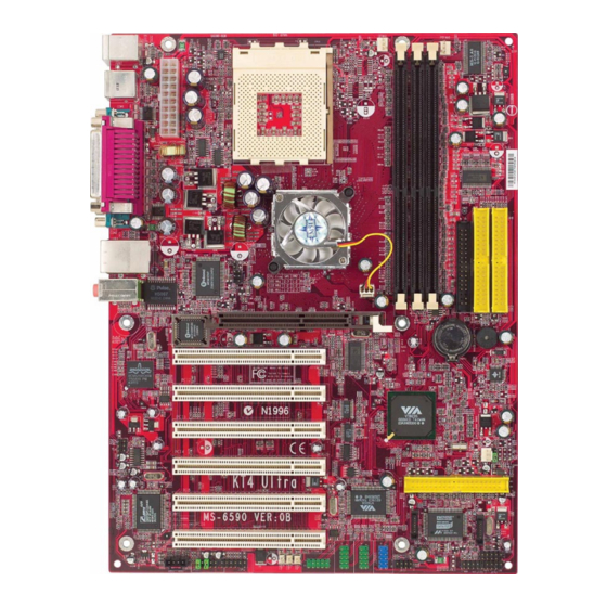
Page 11: Mainboard Layout
Top: LAN jack (Optional) Bottom : US B ports Winbond Line-Out W83697HF Line-In BIOS C-media CMI8738MX JAUD1 KT4 Ultra Series (MS-6590 v1.X) ATX Mainboard CFAN1 SOCKET 462 KT400 JIR1 NBFAN1 AGP Slot PCI Slot 1 PCI Slot 2 VT8235 PCI Slot 3... - Page 12 After rebooting, click Turbo to apply the test result. Click Default to restore the default values. Features: MSI Logo links to the MSI Web site CPU Speed allows users to adjust the CPU speed through CPU Multiplier and FSB...
-
Page 13: Live Bios™/Live Driver
Web site. To use the function, you need to install the “MSI Live Update Series 2” application. After the installation, the “MSI Live Update Series 2” icon (as shown on the right) will appear on the screen. Double click the “MSI Live Update Series 2” icon, and the following screen will appear: Five buttons are placed on the leftmost pane of the screen. -
Page 14: Live Monitor
Live Monitor™ The Live Monitor™ is a tool used to schedule the search for the latest BIOS/drivers version on the MSI Web site. To use the function, you need to install the “MSI Live Update Series 2” application. After the installation, the “MSI Live Monitor” icon (as shown on the right) will appear on the screen. -
Page 15: D-Bracket™ 2 (Optional)
KT3 Ultra2-C ATX Mainboard KT4 Ultra ATX Mainboard D-Bracket™ 2 (Optional) D-Bracket™ 2 is an external USB bracket integrating four Diagnostic LEDs, which use graphic signal display to help users understand their system. The LEDs provide up to 16 combinations of signals to debug the system. The 4 LEDs can debug all problems that fail the system, such as VGA, RAM or other failures. -
Page 16: Getting Started
D-Bracket™ 2 Processor Initialization - This will show information regarding the processor (like brand name, system bus, etc…) Testing RTC (Real Time Clock) Initializing Video Interface - This will start detecting CPU clock, checking type of video onboard. Then, detect and initialize the video adapter. BIOS Sign On - This will start showing information about logo, processor brand name, etc…. - Page 17 KT4 Ultra ATX Mainboard PC Alert™ 4 The PC Alert 4 is a utility you can find in the CD-ROM disk. The utility is just like your PC doctor that can detect the following PC hardware status during real time operation: ö...
- Page 18 CPU and chipset. Right-click the mouse to select the skin you want to switch to. MSI Reminds You... The new feature COOLER XP will work only if your mainboard supports AMD Athlon XP CPU.
-
Page 19: Msi Dvd (5.1 Channel)
Dolby Digital format first. To play DVD with 6-channel audio output, you must configure both the MSI DVD application and the audio codec’s software utility. Otherwise, the 6- channel audio function will not work properly. For information on how to select 6-channel mode in the audio software utility, refer to Appendix. - Page 20 Getting Started 4. Click OK. For more information about MSI DVD, you can refer to the online help coming with the application. To enter the online help: 1. Click on the icon at the bottom-right corner of the control panel.
-
Page 21: Cpu Thermal Protection
SPDIF jack (optical) CPU Thermal Protection Aimed to prevent the CPU from overheating, MSI has developed a CPU Thermal Protection mechanism for AMD Athlon XP CPU platform. This CPU Thermal Protection mechanism works on a thermal signal sensor. If the mecha- nism senses an abnormal temperature rise, it will automatically shut down the system and the CPU temperature will then drop down and resume normal. -
Page 22: Chapter 2. Hardware Setup
Chapter 2. Hardware Setup Hardware Setup This chapter tells you how to install the CPU, memory modules, and expansion cards, as well as how to setup the jump- ers on the mainboard. Also, it provides the instructions on con- necting the peripheral devices, such as the mouse, keyboard, etc. -
Page 23: Quick Components Guide
KT3 Ultra2-C ATX Mainboard KT4 Ultra ATX Mainboard Quick Components Guide JWR1, p.2-8 Back Panel I/O, p.2-9 JIR1, p.2-16 J5, p.2-30 J4, p.2-30 JCD1, p.2-20 JAUD1, p.2-25 CFAN1, p.2-15 CPU, p.2-3 JSP3, p.2-20 JUSB1, p.2-27 J1394_0, J1394_1, J1394_2 , p.2-22 DDR DIMMs, p.2-6... -
Page 24: Central Processing Unit: Cpu
266 MHz 333 MHz OK : Yes. Note 1: Grarantee with MSI certified DDR 400 mudules only. Note 2: User may try this combination, but MSI will not guarantee its functionality. X : Not abaliable . Thermal Issue for CPU AMD Athlon™/Athlon™... -
Page 25: Cpu Installation Procedures For Socket 462
KT3 Ultra2-C ATX Mainboard KT4 Ultra ATX Mainboard CPU Installation Procedures for Socket 462 Please turn off the power and unplug the power cord before installing the CPU. Pull the lever sideways away from the socket. Make sure to raise the lever up to a 90- degree angle. -
Page 26: Installing Amd Athlon Cpu (Socket 462) Cooler Set
4. Connect the fan to the power sup- ply connector provided on your mainboard. MSI Reminds You... Please apply some heat sink paste on top of CPU to dissipate the heat more effectively. Hardware Setup... -
Page 27: Introduction To Ddr Sdram
KT3 Ultra2-C ATX Mainboard KT4 Ultra ATX Mainboard The mainboard provides 3 slots for 184-pin DDR SDRAM DIMM (Double In-Line Memory Module) modules and supports the memory size up to 3GB. You can install PC3200/DDR400, PC2700/DDR333, PC2100/ DDR266 or PC1600/DDR200 modules on the DDR DIMM slots (DDR 1~3). -
Page 28: Ddr Dimm Module Combination
2. Insert the DIMM memory module vertically into the DIMM slot. Then push it in until the golden finger on the memory module is deeply in- serted in the socket. MSI Reminds You... You can barely see the golden finger if the module is properly inserted in the socket. -
Page 29: Atx 20-Pin Power Connector: Jwr1
KT3 Ultra2-C ATX Mainboard KT4 Ultra ATX Mainboard The mainboard supports ATX power supply for the power system. Be- fore inserting the power supply connector, always make sure that all compo- nents are installed properly to ensure that no damage will be caused. -
Page 30: Back Panel
The back panel provides the following connectors: Mouse USB Ports Keyboard COM A Mouse Connector The mainboard provides a standard PS/2 ® for attaching a PS/2 mouse. You can plug a PS/2 connector. The connector location and pin assignments are as follows: PS/2 Mouse (6-pin Female) Back Panel Parallel... -
Page 31: Keyboard Connector
KT3 Ultra2-C ATX Mainboard KT4 Ultra ATX Mainboard Keyboard Connector The mainboard provides a standard PS/2 ® tor for attaching a PS/2 keyboard. You can plug a PS/2 into this connector. PS/2 Keyboard (6-pin Female) USB 2.0 Connectors The mainboard provides a UHCI (Universal Host Controller Interface) Universal Serial Bus root for attaching USB devices such as keyboard, mouse or other USB-compatible devices. -
Page 32: Rj-45 Lan Jack (Optional)
Serial Port Connectors: COM A & COM B The mainboard offers two 9-pin male DIN connectors as serial port COM A & COM B. The ports are 16550A high speed communication ports that send/receive 16 bytes FIFOs. You can attach a serial mouse or other serial devices directly to the connectors. -
Page 33: Parallel Port Connector: Lpt1
KT3 Ultra2-C ATX Mainboard KT4 Ultra ATX Mainboard Parallel Port Connector: LPT1 The mainboard provides a 25-pin female centronic connector as LPT. A parallel port is a standard printer port that supports Enhanced Parallel Port (EPP) and Extended Capabilities Parallel Port (ECP) mode. -
Page 34: Audio Port Connectors
CD player, Tape player, or other audio devices. Mic is a connec- tor for microphones. 1/8” Stereo Audio Connectors MSI Reminds You... For advanced audio application, CMedia 8738MX is provided to offer support for 6-channel audio operation and can turn rear audio connectors from 2-channel to 4-/6-channel audio. -
Page 35: Connectors
KT3 Ultra2-C ATX Mainboard KT4 Ultra ATX Mainboard The mainboard provides connectors to connect to FDD, IDE HDD, case, modem, LAN, USB Ports, IR module and CPU/System/Power Supply FAN. Floppy Disk Drive Connector: FDD1 The mainboard provides a standard floppy disk drive connector that supports 360K, 720K, 1.2M, 1.44M and 2.88M floppy disk types. -
Page 36: Fan Power Connectors: Cfan1/Sfan1/Nbfan1
System Hardware Monitor chipset on-board, you must use a specially de- signed fan with speed sensor to take advantage of the CPU fan control. MSI Reminds You... 1. Always consult the vendors for proper CPU cooling fan. 2. CFAN supports the fan control. You can install the PC Alert utility that will automatically control the CPU fan speed ac- cording to the actual CPU temperature. -
Page 37: Irda Infrared Module Header: Jir1
KT3 Ultra2-C ATX Mainboard KT4 Ultra ATX Mainboard IrDA Infrared Module Header: JIR1 The connector allows you to connect to IrDA Infrared module. You must configure the setting through the BIOS setup to use the IR function. JIR1 is compliant with Intel... -
Page 38: Hard Disk Connectors: Ide1 & Ide2
IDE2 (Secondary IDE Connector) IDE2 can also connect a Master and a Slave drive. MSI Reminds You... If you install two hard disks on cable, you must configure the second drive to Slave mode by setting its jumper. Refer to the hard disk documentation supplied by hard disk vendors for jumper setting instructions. -
Page 39: Hard Disk Raid Connectors: Ide3, Ser1 & Ser2 (Optional)
KT3 Ultra2-C ATX Mainboard KT4 Ultra ATX Mainboard Hard Disk RAID Connectors: IDE3, SER1 & SER2 (Optional) The mainboard has 3 IDE RAID connectors, which are controlled by Promise 20376. IDE3 is a 32-bit Enhanced PCI IDE and Ultra DMA 66/100/133 con- troller that provides PIO mode 0~5, Bus Master, and Ultra DMA 66/100/133 function. - Page 40 SER1 & SER2 Pin Definition Signal Optional Serial ATA cable Connect to SER1 or SER2 MSI Reminds You... Please do not fold the serial ATA cable in a 90-degree angle, which will cause the loss of data during the transmission. Hardware Setup...
-
Page 41: Cd-In Connector: Jcd1
KT3 Ultra2-C ATX Mainboard KT4 Ultra ATX Mainboard CD-In Connector: JCD1 The connector is for CD-ROM audio connector. S-Bracket (SPDIF) Connector: JSP3 (Optional) The connector allows you to connect a S-Bracket for Sony & Philips Digital Interface (SPDIF). The S-Bracket offers 2 SPDIF jacks for digital audio transmission (one for optical fiber connection and the other for coaxial), and 2 analog Line-Out jacks for 4-channel audio output. -
Page 42: Hardware Setup
SIGNAL DESCRIPTION VCC5 VCC 5V SPDFO S/PDIF output Ground LFE-OUT Audio bass output CET-OUT Audio center output 10 Ground Optional S-Bracket Connect to JSP3 SPDIF jack (optical) JSP3 Pin Definition SIGNAL DESCRIPTION VDD3 VDD 3.3V (No Pin) SPDFI S/PDIF input SOUT-R Audio right surrounding output SOUT-L... -
Page 43: Ieee 1394 Connectors: J1394_0, J1394_1, J1394_2 (Optional)
KT3 Ultra2-C ATX Mainboard KT4 Ultra ATX Mainboard IEEE 1394 Connectors: J1394_0, J1394_1, J1394_2 (Optional) The mainboard provides three 1394 pin headers that allow you to con- nect optional IEEE 1394 ports. J1394_0 SIGNAL TPA+ Ground TPB+ Cable power Key (no pin) - Page 44 How to attach the IEEE 1394 Port: 1. Take out the IEEE 1394 Port. 2. Locate the IEEE 1394 connectors (J1394_0, J1394_1 & J1394_2) on the mainboard. 3. Insert the IEEE 1394 Port into the connectors. Match the foolproof design to the Key (no pin) on the J1394 pin to avoid mis-inserting.
-
Page 45: Front Panel Connectors: Jfp1 & Jfp2
KT3 Ultra2-C ATX Mainboard KT4 Ultra ATX Mainboard Front Panel Connectors: JFP1 & JFP2 The mainboard provides two front panel connectors for electrical con- nection to the front panel switches and LEDs. JFP1 is compliant with Intel Front Panel I/O Connectivity Design Guide. - Page 46 AUD_RET_R HP_ON AUD_FPOUT_L AUD_RET_L MSI Reminds You... If you don’t want to connect to the front audio header, pins 5 & 6, 9 & 10 have to be jumpered in order to have signal output directed to the rear audio ports. Otherwise, the Line-Out connector on the back panel will not function.
-
Page 47: Bluetooth Connector: Jbt2 (Optional)
KT3 Ultra2-C ATX Mainboard KT4 Ultra ATX Mainboard Bluetooth Connector: JBT2 (Optional) This connector is used to connect a bluetooth module for wireless connection. JBT2 Pin Definition SIGNAL 5VDUAL D+ (USB signal) D- (USB signal) MSI Reminds You... Because the bluetooth connector shares the USB interface with blue-colored USB2.0 connector, one of the USB2.0 port (see in-... -
Page 48: Front Usb Connectors: Jusb1
Front USB Connectors: JUSB1 The mainboard provides one USB 2.0 pin headers JUSB1 that is ® compliant with Intel I/O Connectivity Design Guide. USB 2.0 technology increases data transfer rate up to a maximum throughput of 480Mbps, which is 40 times faster than USB 1.1, and is ideal for connecting high-speed USB interface peripherals such as USB HDD, digital cameras, MP3 players, printers, modems and the like. -
Page 49: D-Bracket™ 2 Connector: Jled1 (Optional)
KT3 Ultra2-C ATX Mainboard KT4 Ultra ATX Mainboard D-Bracket™ 2 Connector: JLED1 (Optional) The mainboard comes with a JLED1 connector for you to connect to D- Bracket™ 2. D-Bracket™ 2 is a USB Bracket that supports both USB1.1 & 2. -
Page 50: Jumpers
The motherboard provides the following jumpers for you to set the computer’s function. This section will explain how to change your motherboard’s function through the use of jumpers. Clear CMOS Jumper: JBAT1 There is a CMOS RAM on board that has a power supply from external battery to keep the data of system configuration. -
Page 51: Center/Subwoofer Speaker Setting Jumper
KT3 Ultra2-C ATX Mainboard KT4 Ultra ATX Mainboard Center/Subwoofer Speaker Setting Jumper: J4 & J5 (Optional) Some speakers do not design their center and subwoofer audio signals by following the industry standard, which will cause the subwoofer sound pronounces through the center speaker, and the center sound pronounces through the subwoofer speaker. -
Page 52: Slots
The motherboard provides one AGP slot, and six 32-bit PCI bus slots. AGP Slot PCI Slots AGP (Accelerated Graphics Port) Slot The AGP slot allows you to insert the AGP graphics card. AGP is an interface specification designed for the throughput demands of 3D graphics. -
Page 53: Pci Interrupt Request Routing
KT3 Ultra2-C ATX Mainboard KT4 Ultra ATX Mainboard PCI Interrupt Request Routing The IRQ, acronym of interrupt request line and pronounced I-R-Q, are hardware lines over which devices can send interrupt signals to the microprocessor. The PCI IRQ pins are typically connected to the PCI bus INT... -
Page 54: Chapter 3. Bios Setup
Chapter 3. BIOS Setup BIOS Setup This chapter provides information on the BIOS Setup program and allows you to configure the system for optimum use. You may need to run the Setup program when: An error message appears on the screen during the system booting up, and requests you to run SETUP. -
Page 55: Entering Setup
KT3 Ultra2-C ATX Mainboard KT4 Ultra ATX Mainboard Power on the computer and the system will start POST (Power On Self Test) process. When the message below appears on the screen, press <DEL> key to enter Setup. DEL:Setup F11:Boot Menu... -
Page 56: Control Keys
Control Keys < > Move to the previous item Move to the next item < > < > Move to the item in the left hand < > Move to the item in the right hand <Enter> Select the item <Esc>... -
Page 57: The Main Menu
KT3 Ultra2-C ATX Mainboard KT4 Ultra ATX Mainboard The Main Menu Once you enter AMIBIOS NEW SETUP UTILITY, the Main Menu will appear on the screen. The Main Menu displays twelve configurable func- tions and two exit choices. Use arrow keys to move among the items and press <Enter>... - Page 58 BIOS Setup Integrated Peripherals Use this menu to specify your settings for integrated peripherals. PC Health Status This entry shows your PC health status. Frequency/Voltage Control Use this menu to specify your settings for frequency/voltage control. Set Supervisor Password Use this menu to set Supervisor Password. Set User Password Use this menu to set User Password.
-
Page 59: Standard Cmos Features
KT3 Ultra2-C ATX Mainboard KT4 Ultra ATX Mainboard Standard CMOS Features The items inside STANDARD CMOS SETUP menu are divided into 9 categories. Each category includes none, one or more setup items. Use the arrow keys to highlight the item you want to modify and use the <PgUp> or <PgDn>... - Page 60 When Enabled, BIOS will issue a virus warning message and beep if a write to the boot sector or the partition table of the HDD is attempted. Setting options: Disabled and Enabled. MSI Reminds You... This feature only protects the boot sector, not the whole hard disk.
-
Page 61: Advanced Bios Features
KT3 Ultra2-C ATX Mainboard KT4 Ultra ATX Mainboard Advanced BIOS Features Quick Boot Setting the item to Enabled allows the system to boot within 5 seconds since it will skip some check items. Available options: Enabled, Disabled. Full Screen Logo Show This item enables you to show the company logo on the bootup screen. - Page 62 1st/2nd/3rd Boot Device The items allow you to set the sequence of boot devices where AMIBIOS attempts to load the operating system. The settings are: IDE-0 The system will boot from the first HDD. IDE-1 The system will boot from the second HDD. IDE-2 The system will boot from the third HDD.
- Page 63 KT3 Ultra2-C ATX Mainboard KT4 Ultra ATX Mainboard The system will boot from any USB-interfaced ARMD USB RMD-FDD device, such as LS-120 or ZIP drive, that functions as a floppy drive. The system will boot from USB-interfaced ARMD USB RMD-HDD device, such as MO or ZIP drive, that functions as hard disk drive.
- Page 64 Disabled, Enabled. Primary Display This configures the primary subsystem in the computer. Available options: Mono (monochrome), CGA40x25, CGA80x25, VGA/EGA, Absent. Password Check This specifies the type of AMIBIOS password protection that is implemented. Setting options are described below. Option Description Setup The password prompt appears only when end users try to run Setup.
- Page 65 KT3 Ultra2-C ATX Mainboard KT4 Ultra ATX Mainboard Option Description Disabled The specified ROM is not copied to RAM. Enabled The contents of specified ROM are copied to RAM for faster system performance. Cached The contents of specified ROM are not only copied to RAM, the contents of the ROM area can be writ- ten to and read from cache memory.
-
Page 66: Advanced Chipset Features
Advanced Chipset Features MSI Reminds You... Change these settings only if you are familiar with the chipset. DRAM Timing Control Press <Enter> and the following sub-menu appears. Current Host Clock This item shows the current CPU frequency. Configure SDRAM Timing by... - Page 67 KT3 Ultra2-C ATX Mainboard KT4 Ultra ATX Mainboard Detect) EEPROM on the DRAM module. Setting to SPD enables SDRAM Frequency, SDRAM CAS# Latency, Row Precharge Time, RAS Pulse Width, RAS to CAS Delay and SDRAM Bank Interleave auto- matically to be determined by BIOS based on the configurations on the SPD.
- Page 68 Disable the function if 16MB SDRAM is installed. Settings: Disabled, 2-Way and 4-Way. DDR DQS Input Delay This setting allows you to set the delay time of DQS to improve the setup time and hold time of the data, and improve the stability. Setting options: Auto, 18, 08, 0E, 0F.
- Page 69 KT3 Ultra2-C ATX Mainboard KT4 Ultra ATX Mainboard AGP Timing Control Press <Enter> and the following sub-menu appears. AGP Mode The item sets an appropriate mode for the installed AGP card. Setting options: 1x, 2x, 4x, Auto. Select 4x only if your AGP card supports it.
- Page 70 BIOS Setup PCI Delay Transaction The chipset has an embedded 32-bit posted write buffer to support delayed transactions cycles so that transactions to and from the ISA bus are buffered and PCI bus can perform other transactions while the ISA transaction is underway.
-
Page 71: Power Management Features
KT3 Ultra2-C ATX Mainboard KT4 Ultra ATX Mainboard Power Management Features MSI Reminds You... S3-related functions described in this section are available only when your BIOS supports S3 sleep mode. IPCA Function This item is to activate the ACPI (Advanced Configuration and Power Man- agement Interface) function. - Page 72 Auto BIOS determines the best ode automatically. Call VGA BIOS at S3 Resuming Selecting Enabled allows BIOS to call VGA BIOS to initialize the VGA card when system wakes up (resumes) from S3 sleep state. The system resume time is shortened when you disable the function, but system will need an AGP driver to initialize the VGA card.
- Page 73 KT3 Ultra2-C ATX Mainboard KT4 Ultra ATX Mainboard CPU Critical Temperature If the CPU temperature reaches the upper limit preset in this setting, the warn- ing mechanism will be activated. This helps you to prevent the CPU overheat- ing problem.
- Page 74 MSI Reminds You... For “Wake-Up Key” function, the option “Specific Key” refers to the password you specify in the “Wake-Up Password” field. Once you set up a password, it will disable “Resume on PS/2 Mouse”. Resume By Alarm This is used to enable or disable the feature of booting up the system on a scheduled time/date from the soft off (S5) state.
-
Page 75: Pnp/Pci Configurations
KT3 Ultra2-C ATX Mainboard KT4 Ultra ATX Mainboard PNP/PCI Configurations This section describes configuring the PCI bus system and PnP (Plug & Play) feature. PCI, or Peripheral Component Interconnect, is a system which allows I/O devices to operate at speeds nearing the speed the CPU itself uses when communicating with its special components. - Page 76 BIOS Setup PCI Latency Timer This item controls how long each PCI device can hold the bus before another takes over. When set to higher values, every PCI device can conduct transac- tions for a longer time and thus improve the effective PCI bandwidth. For better PCI performance, you should set the item to higher values.
-
Page 77: Integrated Peripherals
KT3 Ultra2-C ATX Mainboard KT4 Ultra ATX Mainboard Integrated Peripherals OnBoard PCI Controller This is used to enable or disable the onboard PCI controller. Please note that the options showed on yout BIOS might be different depending on the motherboard you buy. - Page 78 Serial Port 1/2 These items specify the base I/O port addresses of the onboard Serial Port 1 (COM A)/Serial Port 2 (COM B). Selecting Auto allows AMIBIOS to auto- matically determine the correct base I/O port address. Settings: Auto, 3F8/ COM1, 2F8/COM2, 3E8/COM3, 2E8/COM4 and Disabled.
- Page 79 KT3 Ultra2-C ATX Mainboard KT4 Ultra ATX Mainboard OnBoard IDE Controller This setting controls the onboard IDE controller. Setting options: Disabled, Primary, Secondary, Both. OnChip USB Controller This setting is used to enable/disable the onboard USB ports. Setting options: Disabled, 2 USB Ports, 4 USB Ports, 6 USB Ports...
-
Page 80: Pc Health Status
BIOS Setup PC Health Status This section shows the status of your CPU, fan, overall system status, etc. Monitor function is available only if there is hardware monitoring mecha- nism onboard. Chassis Intrusion The field enables or disables the feature of recording the chassis intrusion status and issuing a warning message if the chassis is once opened. -
Page 81: Frequency/Voltage Control
KT3 Ultra2-C ATX Mainboard KT4 Ultra ATX Mainboard Frequency/Voltage Control Use this menu to specify your settings for frequency/voltage control. Spread Spectrum When the motherboard’s clock generator pulses, the extreme values (spikes) of the pulses creates EMI (Electromagnetic Interference). The Spread Spec- trum function reduces the EMI generated by modulating the pulses so that the spikes of the pulses are reduced to flatter curves. - Page 82 MSI Reminds You... Changing CPU Ratio/Vcore could result in the instability of the system; therefore, it is NOT recommended to change the default setting for long-term usage. DDR Voltage (V) Adjusting the DDR voltage can increase the DDR speed. Any changes made to this setting may cause a stability issue, so changing the DDR voltage for long-term purpose is NOT recommended.
-
Page 83: Set Supervisor/User Password
KT3 Ultra2-C ATX Mainboard KT4 Ultra ATX Mainboard Set Supervisor/User Password When you select this function, a message as below will appear on the screen: Type the password, up to six characters in length, and press <Enter>. The password typed now will replace any previously set password from CMOS memory. -
Page 84: Load High Performance/Bios Setup Defaults
Pressing ‘Enter’ loads the default BIOS values that enable the best sys- tem performance but may lead to a stability issue. MSI Reminds You... The option is for power or overclocking users only. Use of high performance defaults will tighten most timings to increase the system performance. -
Page 85: Appendix A. Using 4- Or 6-Channel Audio Function
Appendix A: Using 4- or 6-Channel Audio Audio Function Function The motherboard comes with C-Media 8738MX chip, which provides support for 6-channel audio output, including 2 Front, 2 Rear, 1 Center and 1 Subwoofer channel SPDIF out. C-Media 8738MX allows the board to attach 4 or 6 speakers for better surround sound effect. -
Page 86: Installing C-Media Drivers
KT4 Ultra ATX Mainboard Installing C-Media Drivers The mainboard is able to transform the audio connectors on the back panel from 2-channel to 4-/6-channel. To use the function, you need to install the C- Media drivers. To install C-Media drivers: Insert the companion CD into the CD-ROM drive. -
Page 87: Hardware Configuration
There are two ways to utilize the function and connect the speakers to your computer: Use the optional S-Bracket. If your motherboard supports S- Bracket and you have installed S-Bracket in the computer, you can connect two speakers to back panel’s Line-Out connector, and the rest of speakers to S-Bracket. -
Page 88: Software Configuration
KT4 Ultra ATX Mainboard Software Configuration To have 4-/6-channel audio work, you must set appropriate configuration in the C-Media software application. Volumn control: To set the Click the C-Media Mixer icon The following screen appears. Click the Then you may adjust the following item: Volumn : This is the master control over all outputs. - Page 89 CD: Regulates the CD drive audio input level. MIC: Regulates the input level of microphone. WAVE: Regulates wave (voice) playback levels. FM: Regulates the FM music play level. AUX IN: Regulates the Auxiliary input play level. LINE IN: Regulates the Line-in level. Advanced: Regulates the advanced settings.
- Page 90 KT4 Ultra ATX Mainboard The Advanced-Speakers Dialog box There are 2 different software configurations in the “Advanced-Speakers” dialog depending the C-Media chipset on your have. Use S/PDIF mode: This diague provides an interface allowing you to set your speaker mode.
- Page 91 Using 4- or 6-Channel Audio Function Use 6-channel: MSI Reminds You... 1. The “S/PDIF Playback” option in the “S/PDIF” dialog will be disabled when you choose “4” or “6” in the “Speaker” option. 2. Without using S-Bracket, the original “Microphone-in” will become “Center/Subwoofer Speaker Out”...
- Page 92 KT4 Ultra ATX Mainboard Using Xear 3D: Xear 3D technology provides a different multi-channel listening method and environment settings. Users can use general open-style earphones to replace real speakers so that users will hear rear-out sounds from the earphone. Using Xear 3D technology, users will need less setup-up effort, cost and space without rear speakers.
- Page 93 Multi-Channel Audio Demo: You can use the “Multi-Channel Audio Demo” application to test the audio setting you are configuring/have configured. The path will be showed as following: Click on each audio output to test the sound effect and the sound configuration.
-
Page 94: Attaching Speakers
KT4 Ultra ATX Mainboard Using 4- or 6-Channel Audio Function Attaching Speakers To perform multichannel audio operation, connect multiple speakers to the system. You should connect the same number of speakers as the audio channels you will select in the software utility. - Page 95 2-Channel Analog Audio Output We recommend that you should still attach the speakers to BACK PANEL’s Line Out connector during 2-channel audio mode even though S-Bracket’s Line Out connectors function properly. Line Out (Front channels) Line In 4-Channel Analog Audio Output Line Out (Front channels) Line In Optical SPDIF jack...
- Page 96 KT4 Ultra ATX Mainboard 6-Channel Analog Audio Output Line Out (Front channels) Line In Optical SPDIF jack Coaxial SPDIF jack Line Out (Center and Subwoofer channel) Line Out (Rear channels) Back Panel Digital Audio Output (2-Channel only) For digital audio output, use the SPDIF (Sony & Philips Digital Interface) connectors supplied by S-Bracket.
- Page 97 Optical SPDIF jack Coaxial SPDIF jack Plug Using 4- or 6-Channel Audio Function Description: Select the correct type of SPDIF jack to connect SPDIF speakers. For optical connection, remove the plug from the S-Bracket before inserting the fiber-optic cable to it. S-Bracket A-13...
- Page 98 JEDEC’s DDR 400 specification is not finalized and standardized yet. But since DDR 400 is becoming more popular in the PC market, we have tested some DDR 400 modules for KT4 Ultra. When using DDR 400 memory, a maximum of 2 DIMMs are recommended.
-
Page 99: Troubleshooting
Q: How do I know what MSI D-LED or D-bracket light mean? A: Please follow the special tech issue, http://www.msi.com.tw/support/ techexpress/special_tech/smartled.htm Q: I have got MSI Motherboard and when it says detecting drives, it detects them but says an error saying "Primary IDE Channel no 80 Conductor Cable Installed"... - Page 100 A: Please refer to the following suggestions: 1. Try the BIOS boot recovery feature as described in http://www.msi.com.tw/support/bios/boot.htm 2. Try to clear the CMOS If problem still persists, ask your reseller for new BIOS chip or contact one of MSI office near your place for new BIOS chip http:// www.msi.com.tw/contact/main.htm...
- Page 101 BIOS, unless you really have to. Q: How do I update the BIOS? A: Please refer to http://www.msi.com.tw/support/bios/note.htm for details. Q: How do I identify the BIOS version? A: Upon boot-up, the 1st line appearing after the memory count is the BIOS version.
- Page 102 KT3 Ultra2-C ATX Mainboard KT4 Ultra ATX Mainboard 6th - 7th digit refers to the customer as MS = all standard customers. V1.0 refers to the BIOS version. 091096 refers to the date this BIOS is released. Q: After flashing the bios and rebooting the system, the screen went blank.
-
Page 103: Glossary
Glossary Glossary Glossary ACPI (Advanced Configuration & Power Interface) This power management specification enables the OS (operating system) to control the amount of power given to each device attached to the computer. Windows 98/98SE, Windows 2000 and Windows ME can fully support ACPI to allow users managing the system power flexibly. - Page 104 KT3 Ultra2-C ATX Mainboard KT4 Ultra ATX Mainboard contents of frequently accessed RAM locations and the addresses where these data items are stored. Chipset A collection of integrated chips designed to perform one or more related functions. For example, a modem chipset contains all the primary circuits for transmitting and receiv- ing data;...
- Page 105 Glossary ECC Memory (Error Correcting Code Memory) A type of memory that contains special circuitry for testing the accuracy of data and correcting the errors on the fly. EEPROM Acronym for Electrically Erasable Programmable Read-Only Memory. An EEPROM is a special type of PROM that can be erased by exposing it to an electrical charge. Like other types of PROM, EEPROM retains its contents even when the power is turned off.
- Page 106 ISA is a standard bus (computer interconnection) architecture that is associated with the IBM AT motherboard. It allows 16 bits at a time to flow between the motherboard circuitry and an expansion slot card and its associated device(s). Also see EISA and MCA.
- Page 107 Glossary LBA (Logical Block Addressing) Logical block addressing is a technique that allows a computer to address a hard disk larger than 528 megabytes. A logical block address is a 28-bit value that maps to a specific cylinder-head-sector address on the disk. 28 bits allows sufficient variation to specify addresses on a hard disk up to 8.4 gigabytes in data storage capacity.
- Page 108 KT3 Ultra2-C ATX Mainboard KT4 Ultra ATX Mainboard PS/2 Port A type of port developed by IBM for connecting a mouse or keyboard to a PC. The PS/2 port supports a mini DIN plug containing just 6 pins. Most modern PCs equipped with PS/2 ports so that the special port can be used by another device, such as a modem.