Table of Contents
Advertisement
WELDER (125, 140, 180 MODELS)
For use with machines having Code Numbers:
TABLE OF CONTENTS
Installation . . . . . . . . . . . . . . . . . . . .Section A
Technical Specifications . . . . . . . . . . . . . . .A-1, A-2
Safety Precautions . . . . . . . . . . . . . . . . . . . . . . .A-2
Stacking . . . . . . . . . . . . . . . . . . . . . . . . . . . . . .A-2
Tilting . . . . . . . . . . . . . . . . . . . . . . . . . . . . . . .A-2
Identify and Locate Components for 180 Amp
and 140 Amp Units . . . . . . . . . . . . . . . . . . . . .A-3
Operation . . . . . . . . . . . . . . . . . . . . .Section B
Safety and Product Description . . . . . . . . . . . . .B-1
Controls and Settings . . . . . . . . . . . . . . . . .B-2, B-3
Drive Roll and Wire Guides Table . . . . . . . . . . . .B-4
6
Setting Up and Making a Aluminum Weld . . . .B-11
Accessories . . . . . . . . . . . . . . . . . . . .Section C
Optional Accessories . . . . . . . . . . . . . . . . . . . . .C-1
Utility Carts . . . . . . . . . . . . . . . . . . . . . . . . .C-2, C-3
Maintenance . . . . . . . . . . . . . . . . . . .Section D
Safety Precautions . . . . . . . . . . . . . . . . . . . . . . .D-1
Wire Feed Compartment, Fan Motor, Wire Reel
Maintenance . . . . . . . . . . . . . . . . . . . . . . . . . .D-1
Gun And Cable Maintenance . . . . . . . . . . . . . . .D-2
Overload Protection . . . . . . . . . . . . . . . . . . . . . .D-2
Component Replacement Procedures . . . . . . . .D-2
Troubleshooting . . . . . . . . . . . . . . . . .Section E
Safety Precautions . . . . . . . . . . . . . . . . . . . . . . .E-1
How to Use Troubleshooting Guide . . . . . . . . . .E-1
Troubleshooting Guide . . . . . . . . . . . . .E-2 thru E-3
Wiring Diagram and Dimension Print . . Section F
Parts Pages . . . . . . . . . . . . . . . .P-532, P-202-E
Cleveland, Ohio 44117-1199 U.S.A. TEL: 216.481.8100 FAX: 216.486.1751 WEB SITE: www.lincolnelectric.com
WIRE FEEDER
11173 thru 11506, 11550, 11658
RETURN TO MAIN MENU
• World's Leader in Welding and Cutting Products •
• Sales and Service through Subsidiaries and Distributors Worldwide •
ISO 9001
ANSI RAB
QMS
Designed and Manufactured Under a
Quality Program Certified by
ABS Quality Evaluations, Inc.
to ISO 9001 Requirements.
CERTIFICATE NUMBER: 30273
Safety Depends on You
Lincoln arc welding and cutting
equipment is designed and built
with safety in mind. However,
your overall safety can be
increased by proper installation
... and thoughtful operation on
your part. DO NOT INSTALL,
OPERATE OR REPAIR THIS
EQUIPMENT WITHOUT READ-
ING THIS MANUAL AND THE
SAFETY PRECAUTIONS CON-
TAINED THROUGHOUT. And,
most importantly, think before
you act and be careful.
Copyright © Lincoln Global Inc.
IMT891-D
June, 2011
Advertisement
Table of Contents

Related Manuals for Lincoln Electric K2481-1


Summary of Contents for Lincoln Electric K2481-1
-
Page 1: Table Of Contents
WIRE FEEDER IMT891-D WELDER (125, 140, 180 MODELS) June, 2011 11173 thru 11506, 11550, 11658 For use with machines having Code Numbers: RETURN TO MAIN MENU TABLE OF CONTENTS Installation ....Section A Technical Specifications . -
Page 2: California Proposition 65 Warnings
351040, Miami, Florida 33135 or CSA Standard W117.2-1974. A Free copy of “Arc Welding Safety” booklet E205 is available from the Lincoln Electric Company, 22801 St. Clair Avenue, Cleveland, Ohio 44117-1199. BE SURE THAT ALL INSTALLATION, OPERATION, MAINTENANCE AND REPAIR PROCEDURES ARE PERFORMED ONLY BY QUALIFIED INDIVIDUALS. -
Page 3: Electric Shock Can Kill
SAFETY ARC RAYS can burn. ELECTRIC SHOCK can 4.a. Use a shield with the proper filter and cover kill. plates to protect your eyes from sparks and 3.a. The electrode and work (or ground) circuits the rays of the arc when welding or observing are electrically “hot”... - Page 4 SAFETY WELDING and CUTTING CYLINDER may explode SPARKS can if damaged. cause fire or explosion. 7.a. Use only compressed gas cylinders 6.a. Remove fire hazards from the welding area. containing the correct shielding gas for the If this is not possible, cover them to prevent process used and properly operating the welding sparks from starting a fire.
- Page 5 NOTES...
- Page 6 Electric for advice or information about their use of our products. We respond to our customers based on the best information in our posses- sion at that time. Lincoln Electric is not in a position to warrant or guarantee such advice, and assumes no liability, with respect to such infor- mation or advice.
-
Page 7: Installation
INSTALLATION TECHNICAL SPECIFICATIONS 180 Amp units (K2481-1, K2515-1, K2659-1, K2689-1, K2698-1) INPUT – SINGLE PHASE ONLY Standard Voltage/Frequency Input Current 230 V 60 Hz 20 Amps @ rated output 208 V 60 Hz 20 Amps @ rated output RATED OUTPUT... -
Page 8: Safety Precautions
INSTALLATION TECHNICAL SPECIFICATIONS 125 Amp units (K2479-1, K2513-1, K2696-1, K2699-1, K2785-1) INPUT – SINGLE PHASE ONLY Standard Voltage/Frequency Input Current 120 V / 60 Hz 20 Amps @ rated output RATED OUTPUT Duty Cycle Current Voltage at Rated Amperes 20% Duty Cycle 90 Amps OUTPUT Welding Current Range... -
Page 9: Identify And Locate Components For 125 Amp Flux Core Unit
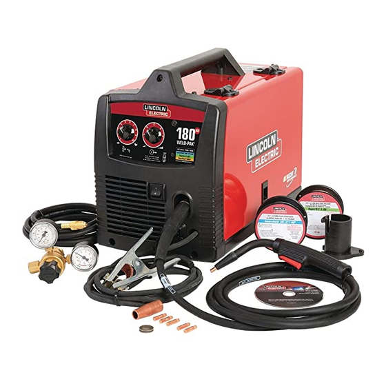
INSTALLATION •Handshield* • Magnum 100L Welding Gun. IDENTIFY AND LOCATE COMPONENTS for 140 AMP and 180 AMP UNITS INCLUDED COMPONENTS Handshield not available on Code 11658. • 3 .035 Contact Tips (1 installed on the welding gun). • Wire Feeder •... -
Page 10: Operation
OPERATION PRODUCT DESCRIPTION (PRODUCT Read entire operation section before CAPABILITIES) operating the WIRE FEEDER WELDERS These small portable wire feed welders are capable of WARNING MIG welding on steel, stainless steel, and aluminum. They are also capable of flux-cored welding on mild steel. -
Page 11: Controls And Settings
OPERATION CONTROLS AND SETTINGS This machine has the following controls: FIGURE B.1 See Figure B.1 1. POWER SWITCH – Turns power on and off to the machine. 2. ARC VOLTAGE CONTROL – This knob sets the output voltage of the machine. Along with wire feed speed (WFS) this control sets a weld procedure. - Page 12 OPERATION FIGURE B.3 See Figure B.3 8. WELDING GUN CONNECTOR BUSHING & THUMBSCREW – Provides electrical power to the welding gun. The thumbscrew holds the welding gun into the connector block. (Front of Machine, Side Door and Wire Drive Cover have been removed for clarity of Items 8 and 9).
-
Page 13: Setting Up And Making A Flux-Cored Weld B-4 Thru B
OPERATION TABLE B.1 DRIVE ROLLS Wire Diameter & Drive Roll Drive Roll Part Type Number .025 MIG wire .025/.030 Smooth Drive Roll KP2529-1 .030 MIG wire .035 MIG wire .035 Smooth Drive Roll KP2529-2 .030 flux-cored .030/.045 Knurled Drive Roll KP2529-3 .035 flux-cored .045 flux-cored... - Page 14 OPERATION B. CONNECT LEADS AND CABLES ON FIGURE B.7 THE MACHINE (See Figure B.7) 1. Open the case side door 2. Slide the connector end of the gun and cable through the hole in the machine front and into the gun connector bushing on the wire drive.
- Page 15 OPERATION FIGURE B.9 (See Figure B.9) 6. Feed the wire through the inlet liner, over the PIVOT ARM ASSEMBLY WITH BEARING PRESSING drive roll groove, thru the outgoing guide and AGAINST DRIVE ROLL wire drive outlet on the gun side. TENSION ARM ASSEMBLY 7.
-
Page 16: Setting Up And Making A Mig Weld And Install Shielding Gas
OPERATION SETTING UP AND MAKING A MIG WELD 7. Work Cable & Clamp A. ITEMS NEEDED FOR MIG WELDING 1. 025 Contact Tip 8. Gas Regulator & Gas Line 3. .025 Drive Roll 4. .025 SuperArc L-56 Solid MIG Wire 9. - Page 17 OPERATION FIGURE B.13 B. INSTALL SHIELDING GAS MIG welding requires an appropriate bottle of shielding MALE END REGULATOR gas. For mild steel either a cylinder bottle of Ar/CO ADAPTER S19298 PLASTIC 100% CO can be used refer to the following instruc- WASHER 100% tions to properly connect shielding gas to the machine.
- Page 18 OPERATION FIGURE B.14 C. CONNECT LEADS AND CABLES ON THE MACHINE LOCATE COMPONENTS TO CONNECT TO THE FRONT OF MACHINE (See Figure B.14) 1. Open the case side door. 2. Slide the connector end of the gun and cable through the hole of the machine front and into the gun connector bushing on the wire drive.
- Page 19 B-10 B-10 OPERATION (See Figure B.16) FIGURE B.16 6. Feed the wire through the inlet liner, over the drive PIVOT ARM ASSEMBLY WITH BEARING PRESSING roll groove, thru the outgoing guide and wire drive AGAINST DRIVE ROLL outlet on the gun side. 7.
-
Page 20: Setting Up And Making A Aluminum Weld
B-11 B-11 OPERATION SETTING UP AND MAKING A ALUMINUM WELD USING SPOOL GUN 1. Follow the MIG welding steps in the previous sec- tion. 2. Connect a bottle of 100% Argon shielding Gas per previous section. 3. Disconnect Magnum 100L Gun. 4. -
Page 21: Accessories
ACCESSORIES K2525-1 - Spot Timer Kit Timer kit, when turned on, allows you to set a fixed weld time so that when the gun trigger is pulled the machine will weld for a fixed time period up to 10 sec- onds. - Page 22 ACCESSORIES K520—Utility Cart Heavy duty cart stores and transports welder, 150 cubic foot shielding gas cylinder, welding cables and accessories. Includes stable platforms for welder and gas bottle platform, lower tray for added storage capacity and adjustable height handle. For mounting welding machines to K520 carts that do not have slotted mounting holes. Drill 9/32”...
- Page 23 ACCESSORIES K2275-1 - Welding Cart Lightweight cart stores and transports welder, 80 cubic foot shielding gas cylinder, welding cables and accessories. Includes an angled top shelf for easy access to controls, lower tray for added storage capacity, a sturdy fixed handle and convenient cable wrap hanger.
-
Page 24: Maintenance
MAINTENANCE MAINTENANCE GUN AND CABLE MAINTENANCE SAFETY PRECAUTIONS FOR MAGNUM™ 100L GUN Gun Cable Cleaning WARNING Clean cable liner after using approximately 300 lbs (136 kg) of solid wire or 50 lbs (23 kg) of flux-cored ELECTRIC SHOCK can kill. wire. -
Page 25: Overload Protection
MAINTENANCE 1-1/4”(31.8 mm) OVERLOAD PROTECTION Liner Trim Length Output Overload The WIRE FEEDER WELDERS (125,140, 180 MOD- ELS) is equipped with a circuit breaker and a thermo- stat which protects the machine from damage if maxi- mum output is exceeded. The circuit breaker button will extend out when tripped. -
Page 26: Troubleshooting
HOW TO USE TROUBLESHOOTING GUIDE WARNING Service and Repair should only be performed by Lincoln Electric Factory Trained Personnel. Unauthorized repairs performed on this equipment may result in danger to the technician and machine operator and will invalidate your factory warranty. For your safety and to avoid Electrical Shock, please observe all safety notes and precautions detailed throughout this manual. - Page 27 TROUBLESHOOTING Observe all Safety Guidelines detailed throughout this manual RECOMMENDED PROBLEMS POSSIBLE COURSE OF ACTION (SYMPTOMS) CAUSE OUTPUT PROBLEMS Major physical or electrical damage “Do not Plug in machine or turn it on”. is evident. Contact your local Authorized Field Service Facility.
- Page 28 TROUBLESHOOTING Observe all Safety Guidelines detailed throughout this manual PROBLEMS POSSIBLE RECOMMENDED (SYMPTOMS) CAUSE COURSE OF ACTION GAS FLOW PROBLEMS Low or no gas flow when gun 1. Check gas supply, flow regulator trigger is pulled. Wire feed, weld and gas hoses. output and fan operate normally.
- Page 29 DIAGRAMS NOTE: This diagram is for reference only. It may not be accurate for all machines covered by this manual. The specific diagram for a particular code is pasted inside the machine on one of the enclosure panels. WIRE FEEDER WELDERS (125, 140, 180 MODELS)
- Page 30 DIMENSION PRINT WIRE FEEDER WELDERS (125, 140, 180 MODELS)