National Instruments FieldPoint FP-2000 User Manual
Hide thumbs
Also See for FieldPoint FP-2000:
- Quick start manual (20 pages) ,
- Quick start manual (19 pages)
Table of Contents
Advertisement
Quick Links
FieldPoint
TM
FP-2000/2010/2015
User Manual
FP-2000/2010/2015 User Manual
Note to Users
The contents of this document that refer to FieldPoint software are
not intended for use with FieldPoint Software 4.0 or LabVIEW 7.0.
Refer to the Measurement & Automation Explorer Help for
FieldPoint and the FieldPoint LabVIEW Interface Help.
April 2003 Edition
Part Number 370705A-01
Advertisement
Table of Contents

Related Manuals for National Instruments FieldPoint FP-2000


Summary of Contents for National Instruments FieldPoint FP-2000
-
Page 1: User Manual
FieldPoint FP-2000/2010/2015 User Manual FP-2000/2010/2015 User Manual Note to Users The contents of this document that refer to FieldPoint software are not intended for use with FieldPoint Software 4.0 or LabVIEW 7.0. Refer to the Measurement & Automation Explorer Help for FieldPoint and the FieldPoint LabVIEW Interface Help. - Page 2 Thailand 662 992 7519, United Kingdom 44 0 1635 523545 For further support information, refer to the Technical Support and Professional Services appendix. To comment on the documentation, send email to techpubs@ni.com. © 2003 National Instruments Corporation. All rights reserved.
-
Page 3: Important Information
The reader should consult National Instruments if errors are suspected. In no event shall National Instruments be liable for any damages arising out of or related to this document or the information contained in it. - Page 4 Bold text also denotes parameter names and LED names. FP-20xx FP-20xx refers to the FP-2000, FP-2010, and FP-2015. italic Italic text denotes variables, emphasis, a cross reference, or an introduction to a key concept. This font also denotes text that is a placeholder for a word or value that you must supply.
-
Page 5: Table Of Contents
Setting Up Security for the FP-20xx ................3-12 Configuring Network Security ................3-12 Locking/Unlocking Settings in Remote System Explorer.......3-13 Downloading Item Information to the FP-20xx .............3-14 Verifying the Configuration...................3-14 Monitoring an I/O Channel ................3-14 Writing to an Output Channel .................3-15 © National Instruments Corporation FP-2000/2010/2015 User Manual... - Page 6 Targeting LabVIEW RT to a Platform ................5-1 Targeting LabVIEW RT to the FP-20xx ............5-1 Targeting LabVIEW RT to the Host PC............5-3 Network Options ......................5-3 RT Target: Access................... 5-4 RT Target: Miscellaneous................5-6 FP-2000/2010/2015 User Manual ni.com...
-
Page 7: Troubleshooting
Hardware Watchdog ......................5-11 Appendix A Choosing Network Settings Appendix B Resetting the FP-20xx Appendix C Troubleshooting Appendix D Installing LabVIEW RT Software Appendix E Specifications Appendix F Technical Support and Professional Services Glossary Index © National Instruments Corporation FP-2000/2010/2015 User Manual... -
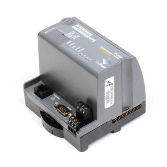
Page 8: Overview Of The Fp-20Xx Network Module
Besides the Ethernet port, the FP-20xx has an RS-232 serial port that is accessible through software. It also has LED indicators to communicate status information and DIP switches that perform various functions. Figure 1-1 shows where these features are located on the FP-20xx. © National Instruments Corporation FP-2000/2010/2015 User Manual... - Page 9 Ethernet network. The module auto-detects the speed of the connection and configures itself accordingly. Figure 1-2 shows an FP-20xx connected to an Ethernet network. For detailed hardware specifications and cabling information, refer to Appendix E, Specifications. FP-2000/2010/2015 User Manual ni.com...
-
Page 10: Fieldpoint Software Overview
• Lookout driver • Measurement Studio instrument drivers • OPC Server You can download a current version of FieldPoint software from the National Instruments Web site. Using your Web browser, go to ni.com © National Instruments Corporation FP-2000/2010/2015 User Manual... -
Page 11: Fp-20Xx Setup Overview
Develop your application, as described in Chapter 5, LabVIEW RT Programming. Launch LabVIEW RT. Develop code. Switch execution target to test code on FP-20xx. Build application by building with LabVIEW RT targeted to .exe FP-20xx. Test embedded application. Deploy system. FP-2000/2010/2015 User Manual ni.com... -
Page 12: Installing The Hardware And Software
Misuse of the product can result in a hazard. You can compromise the safety protection built into the product if the product is damaged in any way. If the product is damaged, return it to National Instruments for repair. © National Instruments Corporation FP-2000/2010/2015 User Manual... - Page 13 . This category is a signal level such as MAINS is defined as the electricity supply system to which the equipment concerned is designed to be connected for either powering the equipment or for measurement purposes. FP-2000/2010/2015 User Manual ni.com...
- Page 14 Installation Category IV is for measurements performed at the source of the low-voltage (< 1,000 V) installation. Examples of Installation Category IV are electric meters, and measurements on primary overcurrent protection devices and ripple-control units. © National Instruments Corporation FP-2000/2010/2015 User Manual...
-
Page 15: Mounting The Fp-20Xx And Terminal Bases
2 Rail Clip Unlocked Hook the lip on the rear of the FP-20xx onto the top of a 35 mm DIN rail and press it down onto the DIN rail, as shown in the following figure. FP-2000/2010/2015 User Manual ni.com... - Page 16 DIN rail by pushing the rail clip to the locked position, as shown in the following figure. After the FP-20xx is mounted to the DIN rail, connect the terminal base to it. © National Instruments Corporation FP-2000/2010/2015 User Manual...
-
Page 17: Connecting Terminal Bases With Din Rail Mounting
DIN rail by placing a screwdriver in the slot on the rail clip and opening it to the unlocked position. After you disconnect the network module from the local bus connector of the terminal base, you can lift it off the rail. FP-2000/2010/2015 User Manual ni.com... -
Page 18: Mounting The Fp-20Xx To A Panel
1 Rail Clip Locked 2 Rail Clip Unlocked Snap the panel-mount accessory onto the module, as shown in the following figure. Lock the panel-mount accessory into place by pushing the rail clip to the locked position. © National Instruments Corporation FP-2000/2010/2015 User Manual... -
Page 19: Connecting Terminal Bases With Panel Mounting
Be careful not to bend any connector pins. Bolt, screw, or otherwise fasten the terminal base to the panel. Make sure that the local bus connectors remain firmly mated after the terminal base is mounted. FP-2000/2010/2015 User Manual ni.com... - Page 20 Wiring Power to the FieldPoint System section for more information about power requirements. If all the pilot holes were correctly drilled, the local bus connectors should remain firmly mated after all the bases are mounted to the panel. © National Instruments Corporation FP-2000/2010/2015 User Manual...
-
Page 21: Removing The Fp-20Xx And Terminal Bases From The Panel
C terminals, those modules should be grouped together. • For more accurate measurements, you might want to locate any thermocouple modules away from heat sources, including network modules or relay modules, unless you are mounting them on an FP-TB-3. FP-2000/2010/2015 User Manual 2-10 ni.com... -
Page 22: Connecting The Fp-20Xx To The Network
To prevent data loss and to maintain the integrity of your Ethernet installation, do not use a cable longer than 100 m. If you are using a 100 Mbps Ethernet, National Instruments recommends using a Category 5 shielded twisted-pair Ethernet cable. © National Instruments Corporation 2-11 FP-2000/2010/2015 User Manual... - Page 23 PC, then reassign a static IP address for the subnet where you want it to be and physically move it to the other subnet. Contact your network administrator if you need assistance configuring the host PC and FP-20xx on the same subnet. FP-2000/2010/2015 User Manual 2-12 ni.com...
-
Page 24: Wiring Power To The Fieldpoint System
Cascading power defeats isolation between the cascaded modules. Caution Connect power to the FieldPoint modules that require external power for inputs or outputs (may include output modules, counter modules, PWM, PG, QUAD). Refer to the I/O module’s operating instructions © National Instruments Corporation 2-13 FP-2000/2010/2015 User Manual... -
Page 25: Calculating Power For A Fieldpoint Bank
This is the amount of power the FP-20xx network module consumes from the power supply to power itself and the I/O modules. It does not include any power consumed by devices that you wire to the terminal bases. FP-2000/2010/2015 User Manual 2-14 ni.com... -
Page 26: Connecting To Field Devices
FieldPoint software. The FieldPoint software installation installs the LabVIEW VIs and examples, Lookout driver class, and LabWindows/CVI instrument driver only if it finds the corresponding development software installed. Close all other applications. © National Instruments Corporation 2-15 FP-2000/2010/2015 User Manual... - Page 27 If the setup does not launch automatically, select Start»Run from Windows, Note , where is the letter of your CD-ROM drive, and select OK. enter d:\setup The hardware and software installation is now complete. Proceed to Chapter 3, Hardware and Software Configuration. FP-2000/2010/2015 User Manual 2-16 ni.com...
-
Page 28: Hardware And Software Configuration
Instruments FieldPoint»FieldPoint Explorer to launch FieldPoint Explorer, shown in the following figure. Click the + sign next to IA Server with OPC in the left pane to expand the view. Then right-click FieldPoint and select Add a comm © National Instruments Corporation FP-2000/2010/2015 User Manual... - Page 29 To use the FP-20xx, set the Type to Ethernet, as shown in the following figure. Each Ethernet comm resource represents a single bank of FieldPoint modules on the network. Click Browse to launch Remote System Explorer, shown in the following figure. FP-2000/2010/2015 User Manual ni.com...
- Page 30 0 and 255, inclusive. • Subnet Mask—A code that helps the network device determine whether another device is on the same subnet or a different subnet. The most common subnet mask is 255.255.255.0 © National Instruments Corporation FP-2000/2010/2015 User Manual...
- Page 31 You must disable resets from FieldPoint Explorer separately by setting user access to Read Only or Deny Access. Refer to the Setting Up Security for the FP-20xx section for more information. FP-2000/2010/2015 User Manual ni.com...
- Page 32 IP address and comment, as shown in the following figure. If it does not appear, select View»Refresh or refer to the FP-20xx Does Not Appear in Remote System Explorer Dialog Box When Browsing section of Appendix C, Troubleshooting. © National Instruments Corporation FP-2000/2010/2015 User Manual...
-
Page 33: Finding And Configuring Devices And Channels
If the Comm Resource Configuration dialog box is not already open, right-click the Comm Resource in FieldPoint Explorer and select Edit this comm resource. If no devices are found, refer to the No Modules Found Error in FieldPoint Explorer section of Appendix C, Troubleshooting. FP-2000/2010/2015 User Manual ni.com... - Page 34 I/O Item is created for each channel on the module, and if all the channels are of the same type, one I/O Item is created to represent all the channels on that module collectively. © National Instruments Corporation FP-2000/2010/2015 User Manual...
- Page 35 Configuration dialog box appears, as shown in the following figure. For output modules, you can choose settings for Watchdog Configuration. Refer to the Guarding against Network Failures (Network Watchdog) section of Chapter 4, Feature Set Description, for more information about the network watchdog feature. FP-2000/2010/2015 User Manual ni.com...
- Page 36 FieldPoint VIs accessing channels on I/O modules attached to the FP-20xx. However, using DataSocket to access channels on the attached I/O modules is considered a network transmission, and the deadband is applied. © National Instruments Corporation FP-2000/2010/2015 User Manual...
-
Page 37: Saving Hardware Configuration As Power-Up State
Description, for more information about configuring and changing the power-up values. Refer to the Guarding against Network Failures (Network Watchdog) section of Chapter 4, Feature Set Description, for information about configuring a network watchdog to guard against network failures. FP-2000/2010/2015 User Manual 3-10 ni.com... -
Page 38: Using Other Features And Options In Remote System Explorer
• Refresh Browse List—Refreshes the list of FP-20xx modules and other National Instruments Ethernet devices found on the local subnet or at the specified IP address. Changes to IP address, comment, and so on do not appear in Remote System Explorer until you reboot the selected system and click Refresh Browse List. -
Page 39: Setting Up Security For The Fp-20Xx
Import checkbox. Then select the source (from file or from device). The settings read from the source are shown in the Access List for you to modify, if needed. FP-2000/2010/2015 User Manual 3-12 ni.com... -
Page 40: Locking/Unlocking Settings In Remote System Explorer
Right-click the Comm Resource in FieldPoint Explorer, choose Edit this comm resource, and click Browse to launch Remote System Explorer. Click the network module, then select Tools»Lock/Unlock Device. A checkmark by this menu item indicates that the device is locked. © National Instruments Corporation 3-13 FP-2000/2010/2015 User Manual... -
Page 41: Downloading Item Information To The Fp-20Xx
Status column shows any error conditions received while communicating with the FieldPoint network. Timestamp is the time when the FP-20xx made the value available to the host PC. Click the red square icon in the toolbar to stop monitoring the items. FP-2000/2010/2015 User Manual 3-14 ni.com... -
Page 42: Writing To An Output Channel
Select the I/O Item in the right pane that corresponds to the channel to which you want to write. Click the pencil and paper icon in the toolbar to write to the I/O channel(s) represented by the I/O Item. © National Instruments Corporation 3-15 FP-2000/2010/2015 User Manual... -
Page 43: Using The Fp-20Xx From Host Applications
FP-20xx from software running on the host PC. Lookout and the FP-20xx The FP-20xx network module integrates easily with National Instruments Lookout 4.0 and later. You can access the module the same way you would access another desktop computer running Lookout. -
Page 44: Labview Vis And The Fp-20Xx
FP Advise. When using FP Advise, you can configure its timing as an input to the VI. Also, do not put more than one FP Advise VI in a loop. All VIs in a © National Instruments Corporation 3-17... -
Page 45: Labwindows/Cvi Functions And The Fp-20Xx
Windows taskbar as FieldPoint Explorer. This help document describes each function in the instrument driver with a description of the C syntax, a description of each parameter, and a list of possible error codes. FP-2000/2010/2015 User Manual 3-18 ni.com... -
Page 46: Fieldpoint Opc Server And The Fp-20Xx
FieldPoint Explorer. However, if the OPC client you are using does not support this feature, you might need to type the Item IDs of the I/O Items directly. The naming convention of the FieldPoint © National Instruments Corporation 3-19 FP-2000/2010/2015 User Manual... -
Page 47: Data Communications
DataSocket was designed as an easy-to-use, high-performance programming interface for sharing and publishing live data in measurement and automation applications. You can use DataSocket VIs to obtain data from other FP-2000/2010/2015 User Manual 3-20 ni.com... - Page 48 Once an item has been highlighted, its URL is displayed in the URL field. You can use copy <Ctrl-C> and paste <Ctrl-V> to insert the URLs into the DataSocket read and write VIs. © National Instruments Corporation 3-21 FP-2000/2010/2015 User Manual...
- Page 49 The Channel Data part of a URL has the following format: \\[machine]\FP\[n]\[channel] where is a two-digit decimal number between 00 and 15. [channel] The following figure shows a DataSocket URL with Channel Data. FP-2000/2010/2015 User Manual 3-22 ni.com...
-
Page 50: Publish Data Vi
Publish Data VI You can use the Publish Data VI on the FieldPoint palette to create items and groups that are published using the National Instruments Ethernet (Lookout) protocol. A host computer or FP-20xx can link to these items using DataSocket or using the native connection capabilities of Lookout or the LabVIEW DSC module. -
Page 51: Feature Set Description
If the network watchdog is enabled and the FP-20xx loses communication with all hosts or clients over the network, the FP-20xx sets its output channels to predefined values (the watchdog state). National Instruments recommends leaving the network watchdog disabled when Note you are running embedded applications on the FP-20xx. -
Page 52: Storing A Custom Power-Up Configuration
Click Snapshot. Click Yes and OK to approve the change. Click OK in the Device Configuration dialog box. Select File»Save. To make incremental changes to the power-up values of individual channels, use the procedure described in the Configurable Power-Up Method section. FP-2000/2010/2015 User Manual ni.com... -
Page 53: Configurable Power-Up Method
Clicking Find Devices removes any tags that have been renamed or added manually. Note To avoid losing tags, add the new I/O module manually. Caution Do not add or remove terminal bases while power is applied to the bank. © National Instruments Corporation FP-2000/2010/2015 User Manual... -
Page 54: Led Indicators
FP-20xx is supplying power to the I/O modules. STATUS LED The red STATUS LED is off in normal operation mode. The FP-20xx indicates specific error conditions by flashing STATUS a specific number of times. Refer to the STATUS LED Error Indications section of FP-2000/2010/2015 User Manual ni.com... -
Page 55: Link Led
READY LEDs turn on and the network module is ready for use. The FP-20xx indicates POST failure through the STATUS LED. If the LEDs do not follow the sequence described here, refer to the STATUS LED © National Instruments Corporation FP-2000/2010/2015 User Manual... -
Page 56: Dip Switches
If you reboot the FP-20xx with the DISABLE VI switch in the ON position, the module does not run any VIs at startup unless you have enabled them through LabVIEW RT. FP-2000/2010/2015 User Manual ni.com... -
Page 57: Safe Mode Switch
, for the location of this port. If you are not running an embedded application, you must target the FP-20xx in order to access the serial port. Refer to Chapter 5, LabVIEW RT Programming, for more information about targeting the FP-20xx. © National Instruments Corporation FP-2000/2010/2015 User Manual... -
Page 58: Isolated Power Connector (Channel 9)
The FP-20xx uses the power supply with the higher voltage level, indicating which supply it is using on channel 9. A value of 0 indicates the primary supply, and a value of 1 indicates the backup supply. FP-2000/2010/2015 User Manual ni.com... -
Page 59: Labview Rt Programming
The following LabVIEW functions are not supported in LabVIEW RT when targeted to your FP-20xx: • ActiveX • Front panel datalogging • Dialog boxes • Printing • Programmatic menus • VISA • Front panel Web publishing • NI-DAQ © National Instruments Corporation FP-2000/2010/2015 User Manual... - Page 60 If the IP address of the host PC appears in the RT Target: Access list of the FP-20xx, you do not need to enter the password. Refer to RT Target: Access section for more information about RT Target: Access. Click OK. FP-2000/2010/2015 User Manual ni.com...
-
Page 61: Targeting Labview Rt To The Host Pc
LabVIEW Help for more information about Performance and Disk, VI Server, and Web Server options. You also can use the following two additional groups of options for LabVIEW RT applications on networked FP-20xx modules: RT Target: Access and RT Target: Miscellaneous. © National Instruments Corporation FP-2000/2010/2015 User Manual... -
Page 62: Rt Target: Access
If a subsequent entry also matches the host PC address, that permission is used in place of the previous permission. For example, in the RT Target: Access dialog box shown, a.test.site.com b.test.site.com FP-2000/2010/2015 User Manual ni.com... - Page 63 RT Engine on the FP-20xx without a password. If the FP-20xx does not have access to a Domain Name Server (DNS), do not use Note domain name entries in the RT Target Access List. Requests to resolve the domain name © National Instruments Corporation FP-2000/2010/2015 User Manual...
-
Page 64: Rt Target: Miscellaneous
LabVIEW RT to the FP-20xx and create an embedded Embedding Applications on the LabVIEW RT application. Refer to the FP-20xx Launching Embedded Applications at Startup sections for more information about embedding and launching LabVIEW RT applications on the FP-20xx. FP-2000/2010/2015 User Manual ni.com... -
Page 65: Embedding Applications On The Fp-20Xx
Select Target Platform dialog box and explicitly specify a target for the application. You can use these command line arguments in a shortcut from your Windows Startup folder to automatically launch © National Instruments Corporation FP-2000/2010/2015 User Manual... -
Page 66: Using Application Builder
Complete the following steps to embed LabVIEW RT applications on your FP-20xx using the Application Builder: Targeting Target LabVIEW RT to your FP-20xx. Refer to the LabVIEW RT to the FP-20xx section for more information. Open a new VI. FP-2000/2010/2015 User Manual ni.com... -
Page 67: Target Tab
Application name, Destination directory, and Support file directory settings in the Application Builder when you target LabVIEW RT to the FP-20xx. Refer to the Network Options section for more information about accessing and using Network Options. © National Instruments Corporation FP-2000/2010/2015 User Manual... -
Page 68: Source Files And Vi Settings Tabs
Target LabVIEW RT to the FP-20xx. Refer to the RT to the FP-20xx section for more information. Select Tools»Network Options. Select RT Target: Miscellaneous from the pull-down menu. Select Launch Application at Boot-up. Click OK. FP-2000/2010/2015 User Manual 5-10 ni.com... -
Page 69: File Transfer Capability
For programmatic file transfer control in LabVIEW or LabVIEW RT, use the Internet Developers Toolkit, included in the LabVIEW Enterprise Connectivity Toolset. Refer to the National Instruments Web site at ni.com for more information about purchasing and using the LabVIEW Enterprise Connectivity Toolset. - Page 70 IP addresses carefully. Consult with your network administrator to obtain appropriate values: • Ask the administrator to provide static IP addresses to your FP-20xx and to the computer running the National Instruments Time Service. Time Service is installed along with the FieldPoint software and runs automatically. •...
- Page 71 • The Time Server is the address of the computer where you have installed the National Instruments Time Service. This service is installed along with the FieldPoint software, Lookout 4.0 or later, and the LabVIEW Datalogging and Supervisory Control module.
- Page 72 . This file has to be placed in the hosts directory, for example windows c:\windows\hosts The file should include the following lines, where is the host name of the FP-20xx and is its IP address: 12.34.56.78 127.0.0.1 localhost 12.34.56.78 fp © National Instruments Corporation FP-2000/2010/2015 User Manual...
- Page 73 Click Browse to launch Remote System Explorer. In Remote System Explorer, double-click the serial number of the FP-20xx whose settings you would like to view or change. When you are done, click OK. Click Cancel to discard any changes you have made. FP-2000/2010/2015 User Manual ni.com...
- Page 74 Power up the FP-20xx and wait for the red STATUS LED to start flashing. When it flashes, the FP-20xx is in reset mode. Move the RESET switch back to the OFF position. Power down the FP-20xx and power it up again. © National Instruments Corporation FP-2000/2010/2015 User Manual...
-
Page 75: Software Configuration Problems
Ethernet network. The module’s POWER and LINK LED indicators should be lit. When you click Browse, the ACTIVE LED on the FP-20xx should flash to indicate that communications are taking place. © National Instruments Corporation FP-2000/2010/2015 User Manual... - Page 76 Possible causes and solutions: • Verify that the IP address entered in Remote System Explorer points to a computer running National Instruments Time Service. • Verify that the time zone settings are set correctly on the host PC and Time Server PC.
- Page 77 Appendix C Troubleshooting • Verify that National Instruments Time Service was installed on the computer you have specified as the Time Server. If Time Service is installed but is not running, restart it either using the service manager or using the following commands.
- Page 78 Repeat the firmware upgrade process. The FP-20xx is in safe mode. Download the software as described in Appendix D, Installing LabVIEW RT Software. 4 (or more) The FP-20xx has detected an unrecoverable error. Contact National Instruments for assistance. FP-2000/2010/2015 User Manual ni.com...
- Page 79 Complete the following steps to install or upgrade the LabVIEW RT software on your FP-20xx: Run Remote System Explorer: right-click the Comm Resource in FieldPoint Explorer, choose Edit this comm resource, and click Browse. © National Instruments Corporation FP-2000/2010/2015 User Manual...
- Page 80 Once you assign the IP address and install the LabVIEW RT software, the FP-20xx is configured for use with LabVIEW RT on the host PC. Refer to Chapter 5, LabVIEW RT Programming, for more information about targeting the FP-20xx and running LabVIEW RT applications. FP-2000/2010/2015 User Manual ni.com...
-
Page 81: Power Requirement
Maximum cabling distance ....100 m/segment Maximum power to connected terminal bases......... 9 W Maximum number of banks ....Determined by network topology Memory FP-2000 ..........16 MB nonvolatile 16 MB DRAM FP-2010 ..........32 MB nonvolatile 32 MB DRAM FP-2015 ..........512 MB nonvolatile... -
Page 82: Physical Characteristics
Electrical immunity ........Evaluated to EN 61326: 1997/A1: 1998, Table 1 For full EMC compliance, you must operate this device with shielded cabling. In Note addition, all cover and filler panels must be installed. See the Declaration of Conformity FP-2000/2010/2015 User Manual ni.com... - Page 83 The following figure shows the connector pinouts for FieldPoint Ethernet cables. Connector 1 Connector 2 pin 1 pin 8 pin 1 pin 8 © National Instruments Corporation FP-2000/2010/2015 User Manual...
- Page 84 Technical Support and Professional Services Visit the following sections of the National Instruments Web site at for technical support and professional services: ni.com • Support—Online technical support resources include the following: – Self-Help Resources—For immediate answers and solutions, visit our extensive library of technical support resources available in English, Japanese, and Spanish at .
- Page 85 You also can visit the Worldwide Offices section of to access the branch ni.com/niglobal office Web sites, which provide up-to-date contact information, support phone numbers, email addresses, and current events. FP-2000/2010/2015 User Manual ni.com...
- Page 86 DIP switch Dual Inline Package switch. Domain Name System. File Transfer Protocol. HotPnP Hot Plug and Play. Input/Output. International Electrotechnical Commission. Light-emitting diode. Meters. OLE for Process Control. Pulse Generation. POST Power-On Self Test. © National Instruments Corporation FP-2000/2010/2015 User Manual...
- Page 87 UDP is for low-overhead transmissions. Volts. Volts direct current. Virtual Instrument. A combination of hardware and/or software elements, typically used with a PC, that has the functionality of a classic stand-alone instrument. Watts. FP-2000/2010/2015 User Manual ni.com...
- Page 88 FieldPoint applications on FP-20xx Explorer, 3-1 troubleshooting software configuration problems, C-1 verification, 3-14 B LED, 4-5 contacting National Instruments, F-2 conventions used in the manual, iv customer education, F-1 C LED, 4-5 professional services, F-1 cables, Ethernet, 2-11, E-3...
- Page 89 FP-20xx, 3-4 cable length (caution), 2-11 configurable power-up state, 4-3 cabling connections (table), E-3 configuration in FieldPoint Explorer, 3-1 connecting FP-20xx to network, 2-11 connecting to network, 2-11 data communication methods, 3-20 DIP switches, 4-6 FP-2000/2010/2015 User Manual ni.com...
- Page 90 OPC server, 3-19 hardware watchdog, 5-11 overview, 3-16 host names, A-3 HotPnP (Hot Plug and Play), 4-3 National Instruments FTP site, 1-3 installation RT Engine FTP server, 5-11 connecting to network, 2-11 mounting FP-20xx on DIN rail, 2-4 mounting FP-20xx to panel, 2-7...
- Page 91 I/O modules, 2-11 embedded applications. See embedded Installer Settings tab in Application applications on FP-20xx Builder, 5-10 FieldPoint VIs, 3-17 instrument drivers, F-1 hardware watchdog VIs, 5-11 IP Access List, 3-12, 3-13 LabVIEW FieldPoint VIs, 4-7 FP-2000/2010/2015 User Manual ni.com...
- Page 92 LabVIEW RT applications at system startup, 5-6, 5-10 technical support, F-1 overview, 2-15 worldwide offices, F-2 runaway startup applications, C-4 network module. See FP-20xx hardware power-up state, configurable, 4-3 network security settings, 3-12 network specifications, E-1 © National Instruments Corporation FP-2000/2010/2015 User Manual...
- Page 93 2-10 network security settings, 3-12 testing password-protected resets, 3-4 power-on self test (POST), 4-5 serial data communication, 3-23 verifying configuration in FieldPoint serial port, 1-1, 3-23, 4-7 Explorer, 3-14 serial VIs, 4-7 FP-2000/2010/2015 User Manual ni.com...
- Page 94 2-15 errors, C-1 power, 2-13 runaway startup applications, C-4 power (figure), 2-14 STATUS LED error indications worldwide technical support, F-2 (table), C-4 writing to an output channel, 3-15 troubleshooting resources, F-1 © National Instruments Corporation FP-2000/2010/2015 User Manual...