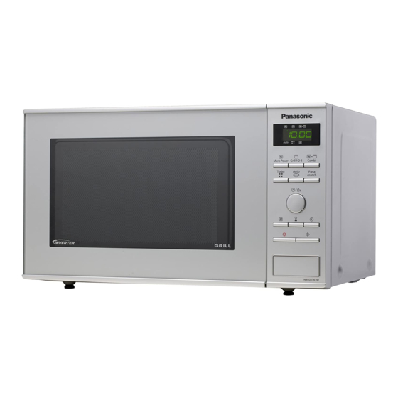
Panasonic NN-GD371S Service Manual
Microwave oven
Hide thumbs
Also See for NN-GD371S:
- Operating instructions manual (38 pages) ,
- Operating instruction and cook book (58 pages)

Related Manuals for Panasonic NN-GD371S


Summary of Contents for Panasonic NN-GD371S
-
Page 1: Microwave Oven
ORDER NO.PHAMOS1106061CE Microwave Oven NN-GD371S NN-GD361M NN-GD351W BPQ (U.K.) EPG (Continental Europe) WPG (Switzerland) © Panasonic Home Appliances Microwave Oven (Shanghai) Co., Ltd. 2011. - Page 2 NN-GD371S / NN-GD361M / NN-GD351W...
- Page 3 NN-GD371S / NN-GD361M / NN-GD351W...
-
Page 4: Table Of Contents
NN-GD371S / NN-GD361M / NN-GD351W CONTENTS Page Page 1 FEATURE CHART 7.1. Primary, Secondary Latch Switch interlocks & Power 2 CONTROL PANEL Relay RY1 3 SCHEMATIC DIAGRAM 7.2. Short switch & monitor 4 DESCRIPTION OF OPERATING SEQUENCE 7.3. Magnetron 4.1. Variable power cooking control 7.4. -
Page 5: Feature Chart
NN-GD371S / NN-GD361M / NN-GD351W 1 FEATURE CHART 2 CONTROL PANEL... -
Page 6: Schematic Diagram
NN-GD371S / NN-GD361M / NN-GD351W 3 SCHEMATIC DIAGRAM... -
Page 7: Description Of Operating Sequence
NN-GD371S / NN-GD361M / NN-GD351W 4 DESCRIPTION OF OPERATING SEQUENCE 4.1. Variable power cooking 4.3. Inverter defrost, Auto menu & control Auto reheat High Voltage Inverter Power Supply (U) controls output power When the Auto Control feature is selected and the Start button by the signal from Digital Programmer Circuit (DPC). -
Page 8: Cautions To Be Observed When Troubleshooting
NN-GD371S / NN-GD361M / NN-GD351W 5 CAUTIONS TO BE OBSERVED WHEN TROUBLESHOOTING Unlike many other appliances, the microwave oven is a high voltage, high current device. It is free from danger in ordinary use, though extreme care should be taken during repair. -
Page 9: Part Replacement
NN-GD371S / NN-GD361M / NN-GD351W 5.3. Part replacement. 5.7. Sharp edges When troubleshooting any part or component is to be replaced, CAUTION always ensure that the power cord is unplugged from the wall Please use caution when disassembling or reassembling outlet. -
Page 10: Disassembly And Parts Replacement Procedure
NN-GD371S / NN-GD361M / NN-GD351W 6 DISASSEMBLY AND PARTS REPLACEMENT PROCEDURE 6.1. Magnetron 6. Remove 2 screws holding the magnetron. 1. Discharge the high voltage capacitor. 2. Remove 1 screw holding front plate bracket on cavity top plate. 3. Remove 2 screws holding air guide A on cavity top plate and on magnetron. -
Page 11: Low Voltage Transformer And/Or Power Relays (Ry1)
NN-GD371S / NN-GD361M / NN-GD351W 6.4. DC fan motor 2. Disconnect 1 grounding connector from cavity front plate. 1. Disconnect DC fan motor connect CN15 from DPC board 2. Remove 2 screws holding orifice assy and detach the orifice assy from oven assy. -
Page 12: Door Assembly
NN-GD371S / NN-GD361M / NN-GD351W 3. Remove door C from door A (U) & door E by carefully 6.5. Door assembly pulling outward starting from upper right hand corner using a flat blade screwdriver. 1. Support the door, remove 2 screws holding hinge A. -
Page 13: Turntable Motor
NN-GD371S / NN-GD361M / NN-GD351W 6.6. Turntable motor 9. Tighten 2 mounting screws. 1. Remove the motor cover by breaking off at the 4 spots indicated by arrows with a cutter or the like. NOTE: After removing the motor cover, be sure that cut... -
Page 14: Quartz Heater
NN-GD371S / NN-GD361M / NN-GD351W 6.8. H.V. Inverter Power Supply 6.7. Quartz heater 1. Disconnect 2 high voltage lead wires from magnetron 1. Disconnect lead wires from both side of heater terminals. filament terminals. 2. Bend back 2 locking tabs from left and right side of upper 2. - Page 15 NN-GD371S / NN-GD361M / NN-GD351W 6. Remove 2 screws holding H.V. inverter on the inverter bracket.
-
Page 16: Component Test Procedure
NN-GD371S / NN-GD361M / NN-GD351W 7 COMPONENT TEST PROCEDURE 7.3. Magnetron WARNING 1. High voltage is present at the output terminals of the High Voltage Inverter (U) including aluminum heat sink during any cook cycle. Continuity checks can only indicate an open filament or a 2. -
Page 17: Inverter Power Supply (U)
NN-GD371S / NN-GD361M / NN-GD351W 7.5. Inverter power supply (U) d. Press Micro Power button once. DO NOT try to REPAIR H.V. Inverter power supply 5. Program oven at High power for 1 minute and press [Start] (U).Replace complete H.V. Inverter(U) Unit. -
Page 18: Measurements And Adjustments
NN-GD371S / NN-GD361M / NN-GD351W 8 MEASUREMENTS AND ADJUSTMENTS 8.1. Adjustment of Primary latch 8.2. Measurement of microwave switch, Secondary latch output switch and Short switch. The output power of the magnetron can be determined by performing IEC standard test procedures. However, due to the 1. -
Page 19: Troubleshooting Guide
NN-GD371S / NN-GD361M / NN-GD351W 9 TROUBLESHOOTING GUIDE DANGER: HIGH VOLTAGES 1. DO NOT RE-ADJUST PRESET CONTROL on the H.V.Inverter (U). It is very dangerous to repair or adjust without proper test equipment because this circuit generates very large current and high voltage. Operating a misaligned inverter circuit is dangerous. - Page 20 NN-GD371S / NN-GD361M / NN-GD351W SYMPTOM CAUSE CORRECTIONS 1. Oven is dead. 1. Open or loose lead wire harness Fuse is OK. 2. Open thermal cutout / thermistor Check thermal cutout is defective. No display and no operation at all.
-
Page 21: Troubleshooting Of Inverter Circuit (U) And Magnetron
NN-GD371S / NN-GD361M / NN-GD351W 9.2. Troubleshooting of inverter circuit (U) and magnetron This oven is programmed with a self diagnostics failure code system which will help for troubleshooting. H95, H97, H98 and H99 are the provided failure codes to indicate magnetron and inverter circuit problem areas. This section explains failure codes of H95, H97, H98 and H99. -
Page 22: Simple Way Of H.v. Inverter/Magnetron Troubleshooting
NN-GD371S / NN-GD361M / NN-GD351W 9.3. Simple way of H.V. Inverter/magnetron troubleshooting Purpose: Simple way (3/23 seconds rule) of identifying whether it’s Magnetron, Inverter, or others. Set-up: The unit under question is connected through the Ammeter as shown below. Procedure: Follow the matrix table below to identify the problem source. -
Page 23: Inverter Main Parts List (Z606Yba00Gp)
NN-GD371S / NN-GD361M / NN-GD351W 9.5. H.V. INVERTER MAIN PARTS LIST (Z606YBA00GP) Ref. No. Part No. Part Name & Description Pcs/Set Remarks Q701 Z1JAEV000003 IGBT C701 ZCWHC3B104JA FILM CAPACITOR 0.1µF,1000VDC C702 ZCWF4305N851 FILM CAPACITOR 3µF,250VDC DB701 Z0FBBQ000006 RECTIFIER BRIDGE L701... -
Page 24: Exploded View And Parts List
NN-GD371S / NN-GD361M / NN-GD351W 10 EXPLODED VIEW AND PARTS LIST 10.1. EXPLODED VIEW... -
Page 25: Parts List
NN-GD371S / NN-GD361M / NN-GD351W 10.2. PARTS LIST NOTE: 1. When ordering replacement part(s), please use part number(s) shown in this part list. Do not use description of the part. 2. Important safety notice: Components identified by mark have special characteristics important for safety. -
Page 26: Escutcheon Base Assembly
NN-GD371S / NN-GD361M / NN-GD351W 10.3. ESCUTCHEON BASE ASSEMBLY 10.3.1. NN-GD371S Ref. No. Part No. Part Name & Description Pcs/Set Remarks Z603LBB10BP D.P.CIRCUIT (AU) GD371S BPQ Z603LBB10EP D.P.CIRCUIT (AU) GD371S EPG Z603LBB10WP D.P.CIRCUIT (AU) GD371S WPG Z603YBB10BP D.P.CIRCUIT (DU) Z800LBB10SBP... - Page 27 NN-GD371S / NN-GD361M / NN-GD351W 10.3.2. NN-GD361M, GD351W Ref. No. Part No. Part Name & Description Pcs/Set Remarks Z603LBB10EP D.P.CIRCUIT (AU) GD361M EPG,GD351W EPG Z603YBB10BP D.P.CIRCUIT (DU) Z8034BA10SBP ESCUTCHEON BASE GD361M Z8034BA10HBP ESCUTCHEON BASE GD351W Z891PBA10SBP DOOR OPENING BUTTON (U)
-
Page 28: Door Assembly
NN-GD371S / NN-GD361M / NN-GD351W 10.4. DOOR ASSEMBLY Ref. No. Part No. Part Name & Description Pcs/Set Remarks Z30189V00XP DOOR KEY A Z302KBA00EP DOOR E (U) Z30215G10XN DOOR KEY SPRING Z30859V00XP DOOR C Z3145BB10EP DOOR SCREEN A Z302ABB10SEP DOOR A (U) -
Page 29: Wiring Materials
NN-GD371S / NN-GD361M / NN-GD351W 10.5. WIRING MATERIALS Ref. No. Part No. Part Name & Description Pcs/Set Remarks Z030ABB10BP LEAD WIRE HARNESS Z030EBA00EP H.V.LEAD WIRE... -
Page 30: Packing And Accessories
NN-GD371S / NN-GD361M / NN-GD351W 10.6. PACKING AND ACCESSORIES Ref. No. Part No. Part Name & Description Pcs/Set Remarks Z0003BB10BP INSTRUCTION MANUAL Z0003BB30EP INSTRUCTION MANUAL Z0003BB10WP INSTRUCTION MANUAL Z0102BB10SBP PACKING CASE, PAPER GD371S BPQ Z0102BB10SEP PACKING CASE, PAPER GD371S EPG,GD371S WPG... -
Page 31: Digital Programmer Circuit
NN-GD371S / NN-GD361M / NN-GD351W 11 DIGITAL PROGRAMMER CIRCUIT 11.1. SCHEMATIC DIAGRAM... - Page 32 NN-GD371S / NN-GD361M / NN-GD351W 06/11 S-BB1 S-BB3 S-BB4 Printed in China...