Jøtul GF 100 DV Nordic QT Installation And Operation Instructions Manual
Jotul gas heater installation and operation instructions
Hide thumbs
Also See for GF 100 DV Nordic QT:
- Installation and operation instructions manual (32 pages) ,
- Installation and operation instructions manual (36 pages) ,
- Installation and operation instructions manual (32 pages)
Table of Contents
Advertisement
Jøtul GF 100 DV
Nordic QT
Gas Heater
Installation
and
Operation
Instructions
IF THE INFORMATION IN THESE INSTRUCTIONS
ARE NOT FOLLOWED EXACTLY, A FIRE OR EX-
PLOSION MAY RESULT CAUSING PROPERTY
DAMAGE, PERSONAL INJURY OR LOSS OF LIFE.
FOR YOUR SAFETY:
DO NOT STORE OR USE GASOLINE OR OTHER
FLAMMABLE VAPORS AND LIQUIDS IN THE
VICINITY OF THIS OR ANY OTHER APPLIANCE.
INSTALLATION:
INSTALLATION AND SERVICE MUST BE PER-
FORMED BY A QUALIFIED INSTALLER, SER-
VICE AGENCY OR LICENSED GAS SUPPLIER.
WHAT TO DO IF YOU SMELL GAS:
• DO NOT TRY TO LIGHT ANY APPLIANCE.
• DO NOT TOUCH ANY ELECTRICAL
SWITCHES.
• DO NOT USE THE PHONE IN YOUR
BUILDING. IMMEDIATELY CALL YOUR GAS
SUPPLIER FROM A NEIGHBOR'S PHONE.
• FOLLOW YOUR GAS SUPPLIER'S
INSTRUCTIONS.
• IF YOU CANNOT REACH YOUR GAS
SUPPLIER, CALL THE FIRE DEPARTMENT.
AVERTISSEMENT:
ASSUREZ-VOUS DE BIEN SUIVRE LES IN-
STRUCTIONS DANS CETTE NOTICE POUR
REDUIRE AU MINIMUM LE RISQUE D'INCENDIE
OU POUR EVITER TOUT DOMMAGE MATERIEL,
TOUTE BLESSURE OU MORTALIT'E.
NE PAS ENTREPOSER NI UTILISER D'ESSENCE
NI OU LIQUIDES INFLAMMABLES DANS LE
VOISINAGE DE CET APPAREIL OU DE TOUT
AUTRE APPAREIL.
L'INSTALLATION LE SERVICE DOIVENT
ETRE EXECUTES PAR UN INSTALLATEUR
QUALIFIE, AGENCE DE SERVICE OU LE
FOURNISSEUR DE GAZ.
QUE FAIRE SI VOUS SENTEZ UNE ODEUR DE GAZ.
• NE PAS TENTER D'ALLUMER L'APPAREIL
• NE TOUCHEZ A AUCUM NTERRUPTEUR.
• NE PAS VOUS SERVIR DES TELEPHONES SE
TROUVANT DANS LE BATIMENT OU VOUS
VOUS TROUVEZ.
• APPELEZ IMMEDIATEMENT VOTRE
FOURNISSEUR DE GAZ CHEZ UN VOISIN. SUIVEZ
LES INSTRUCTIONS DU FOURNISSEUR.
• SI VOUS NE POUVEZ REJOINDRE LE
FOURNISSEUR DE GAZ, APPELEZ LE SERVICE
DES INCENDIES.
WARNING:
1
Advertisement
Table of Contents

Related Manuals for Jøtul GF 100 DV Nordic QT


Summary of Contents for Jøtul GF 100 DV Nordic QT
- Page 1 Jøtul GF 100 DV Nordic QT Gas Heater Installation Operation Instructions WARNING: IF THE INFORMATION IN THESE INSTRUCTIONS ARE NOT FOLLOWED EXACTLY, A FIRE OR EX- PLOSION MAY RESULT CAUSING PROPERTY DAMAGE, PERSONAL INJURY OR LOSS OF LIFE. FOR YOUR SAFETY: DO NOT STORE OR USE GASOLINE OR OTHER FLAMMABLE VAPORS AND LIQUIDS IN THE VICINITY OF THIS OR ANY OTHER APPLIANCE.
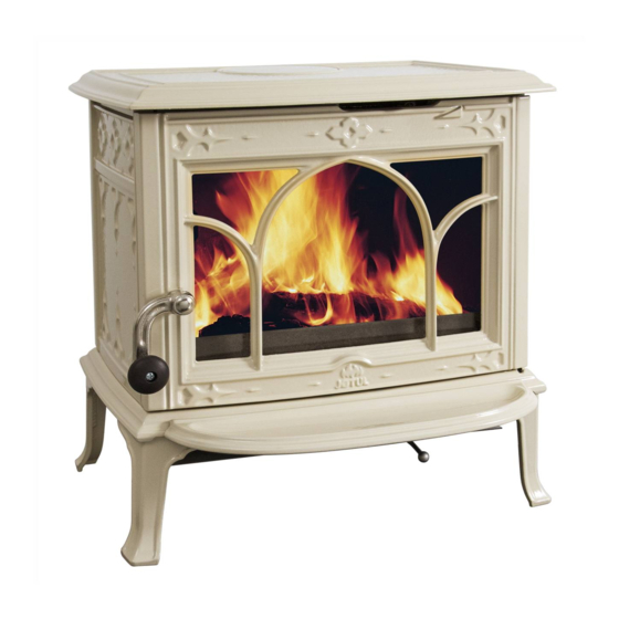
- Page 2 With proper use and care, your Jøtul stove will provide you with many years of safe, dependable and satisfying service. The Jøtul GF100 DV Nordic QT is a direct vented gas heater designed and approved for installation into a variety of configurations where close clearance to combustible material is required.
-
Page 3: Table Of Contents
Lighting Instructions ... Back Cover THIS PRODUCT MUST BE INSTALLED BY A LICENSED PLUMBER OR GAS-FITTER WHEN INSTALLED IN THE COMMON- WEALTH OF MASSACHUSETTS. Jøtul GF100 DV Nordic QT Direct Vent Gas Heater Manufactured and Distributed by: Jøtul A.S.A. Fredrikstad, Norway Jøtul North America... -
Page 4: Specifications
GF 100 DV Nordic QT Specifications Input Rates Natural Gas 14,500 BTU/hr. maximum input 10,600 BTU/hr. minimum input Propane 14,000 BTU/hr. maximum input 10,900 BTU/hr. minimum input Inlet Pressure: Natural Gas: 5.0 WC (1.24 kPa) Propane: 11.0 WC (2.74 kPa) Manifold Pressure: Natural Gas: 2.2 WC (.55 kPa) Propane:... -
Page 5: General Information
General Information THIS HEATER MUST BE INSTALLED AND MAINTAINED BY A QUALIFIED SERVICE AGENCY. The installation and repair of this appliance must be done by a qualified service person. Failure to properly install and maintain this heater could result in an unsafe or hazardous installation, which may result in a fire, explosion, property damage, personal injury or loss of life. -
Page 6: Safety Information
Safety Information During normal operation, the Nordic QT gas stove will reach high surface temperatures. Therefore: Due to the high operating temperatures, this appli- ance should be located out of traffic areas and away from furniture and draperies. Children and adults should be alerted to the hazards of high surface temperatures and should stay away to avoid burns and/or clothing ignition. -
Page 7: Clearances
Stove and Vent Clearance Requirements Minimum Clearances from the Stove to Combustibles: See figs. 2-4. Rear: 0” (0 mm) Ceiling: 25” (635 mm) Corner: 2” (50 mm) Right Side: 3” (76 mm) Left Side: 10” (254 mm) - for access to Lighting Instruction plate Minimum Clearances from the Vent Pipe to Combus- tibles: Horizontal Run:... -
Page 8: Vent Requirements Adding Restriction
Venting Requirements The Jøtul GF100 Nordic QT gas stove may be installed with a vertical or horizontal termination and must conform to the configuration requirements described below. This appliance is approved for use with vent systems from the following manufacturers: •... -
Page 9: Vent Termination
Vertical Venting The Jøtul GF100 DV Nordic QT is approved for vertical venting through a ceiling or to a roof termination following these guidelines: The termination should fall within the shaded area of the grid depicted in fig. 6 below. -
Page 10: Horizontal Termination
Horizontal Termination Wall Cut-out Opening: A minimum 10" X 10" (250 mm x 250 mm) square hole is required for proper pipe clear- ances through a combustible wall. Use vent manufacturer’s WALL THIMBLE for the wall penetration. DO NOT FILL AIR SPACE WITH ANY TYPE OF INSULATION. The minimum horizontal run made directly off the rear of the stove into a standard horizontal cap shall be no less than a 6”... - Page 11 Figure 11. CORNER INSTALLATION 45° Elbow 1 2 3 1 2 3 1 2 3 1 2 3 1 2 3 1 2 3 1 2 3 1 2 3 Max. Horizontal Run into a STANDARD HORIZONTAL CAP : 45° elbow + 9” + 6” sections (totalling 17” horizontal).
-
Page 12: Vent Terminal Clearances
Horizontal Termination Clearance Figure 15. Vent Terminal Clearances - National Fuel Gas Code. A = Clearance above grade, veranda, porch , deck, or balcony : *12 inches (30 cm) minimum. B = Clearance to window or door that may be opened: 9 inches (23 cm) min./U.S. -
Page 13: Mobile Home Installation
Mobile Home Installation The Nordic QT can be installed for use in a mobile home in the U.S. and Canada provided: 1. The stove is secured to the floor of the mobile home. Use Jøtul Floor Bracket Kit #154388. 2. Provision must be made to secure an electrical ground between the stove and the mobile home chassis. - Page 14 Gas Conversion Procedure Refer to fig. 27, Illustrated Parts Breakdown, to identify part numbers below. 1. Turn off gas supply to stove. 2. Remove the stove Top Plate (3). 3. Remove the front plate from the stove. Pull the casting straight up and out away from the side panels.
-
Page 15: Gas Connection
Gas Supply Connection The gas supply line connection is made to the valve just inside the left rear leg. The gas supply line should be 3/8" npt with a 1/2" diameter supply, or the appropriate size to provide sufficient gas pressure to the valve regardless of the input setting. -
Page 16: Gas Pressure
Gas Pressure Correct gas pressure is essential for efficient and safe operation of the Nordic QT gas stove. It is important that the correct pressure is established at the time of the installation. Proper gas pressure provides a consistent flow of gas to the appliance and is instrumental in checking for gas leaks. -
Page 17: Air Shutter Adjustment
Flame Appearance / Air Shutter Adjustment The GF100 DV NORDIC QT gas stove is shipped from the factory equipped to burn Natural gas. If the stove has been converted for use with propane, will require adjust- ment. -
Page 18: Wall Thermostat
Optional Wall Thermostat or Remote Control Use only a 750 millivolt DC two-wire circuit thermostat with this appliance. The thermostat should be placed in the same room as the heater, typically 5 feet off the floor. Avoid drafty areas or any area that may affect the accuracy of the thermostat. -
Page 19: System Check
System Check 1. PURGING THE GAS LINE: When lighting the appli- ance for the first time, it will take a few moments to clear the gas line of air. Once this purge is complete, the appliance will operate as described in the lighting instructions. -
Page 20: Operation
Operation Familiarize yourself with the controls of the GF100 Nordic QT. Make sure that anyone else using the appli- ance is also familiar with the controls and operation procedures. Always follow the Lighting Instructions on the inside back cover of this manual and also located on the Rating Plate attached to the burner assembly. -
Page 21: Glass Replacement
MAKE IT AVAILABLE TO ANYONE USING OR SERVICING THE STOVE. Record the following information to help your dealer determine what you will need for parts and service. GF100 DV Nordic QT MODEL NAME: ________________________ SERIAL NUMBER: ______________________ DATE OF PURCHASE: ___________________ PURCHASED FROM: ____________________... -
Page 22: Illustrated Parts Breakdown
GF100 Nordic QT Illustrated Parts Breakdown Figure 29. Illustrated Parts Breakdown - GF100 Nordic QT... -
Page 23: Replacement Parts List
GF100 Nordic QT Parts List Cast Iron Parts Matte Black Front Panel 10390992 Side Panel 10391192 Top Casting 10391092 Glass Frame ... 129392 Glass Gasket (7/16” x 5 ft tadpole) ... Glass Panel ... 129393 Glass Frame Kit (includes 4,5 & 6) . 154983 Glass Clip ... -
Page 27: Lighting Instructions
LIGHTING INSTRUCTIONS FOR YOUR SAFETY, READ BEFORE LIGHTING. IF YOU DO NOT FOLLOW THESE INSTRUCTIONS EXACTLY, A FIRE OR EXPLOSION MAY RESULT CAUSING PROPERTY DAMAGE, PERSONAL INJURY, OR LOSS OF LIFE. A. This appliance has a pilot which must be lit by hand. - Page 28 This appliance must be installed in conformance with local and national building regulations. Before beginning the installation, it is important that the these instructions be carefully read and understood. Jøtul maintains a policy of continual product development. Consequently, products may differ in specification, color or type of accessories from those illustrated or described in various publications.