
Related Manuals for Jonsered GR 2026D


Summary of Contents for Jonsered GR 2026D
- Page 1 Operator´s manual (EPA) Read through the Operator's Manual carefully and understand the content before using the machine.
-
Page 2: Symbol Explanation
SYMBOL EXPLANATION Symbols WARNING! Clearing saws, brushcutters and trimmers can be dangerous! Careless or incorrect use can result in serious or fatal injury to the operator or others. Read through the Operator‘s Manual carefully and understand the content before using the machine. Always use •... -
Page 3: Table Of Contents
Jonsered has a policy of continuous product development and therefore reserves the right to modify the design and appearance of products without prior notice. Maintenance, replacement, or repair of the emission control devices and systems may be performed by any nonroad engine repair establishment or individual. -
Page 4: Safety Instructions
Personal protective equipment IMPORTANT INFORMATION • Incorrect or careless use of a clearing saw, brushcutter or trimmer can turn it into a dangerous tool that can cause serious or even fatal injury to the operator or others. It is extremely important that you read and understand the content of this manual. - Page 5 2. Stop switch The stop switch should be used to stop the engine. 3. Cutting attachment guard This guard is intended to prevent objects from being thrown towards the operator and to protect the operator from unintentionel contact with the cutting attachment. WARNING! Do not attach any blade to the unit without proper installation of all required parts.
- Page 6 6. Muffler The muffler is designed to give the lowest possible noise level and to direct the engine‘s exhaust fumes away from the operator. Muffler fitted with catalytic converter is also designed to reduce harmful exhaust components. In countries that have a warm and dry climate the risk of fire is obvious.
-
Page 7: Control, Maintenance And Service Of The Machine's Safety Equipment
Control, maintenance and service of the machine‘s safety equipment IMPORTANT INFORMATION • All service and repairs to the machine require special training. • This applies especially to the machine‘s safety equipment. If the machine does not meet any of the controls listed below you should contact your service workshop. - Page 8 3. Cutting attachment guard • Check that the guard is undamaged and not cracked. • Replace the guard if it has been exposed to impact or is cracked. • Always use the prescribed blade an guard combination, see chapter "Technical data". 4.
-
Page 9: Cutting Equipment
6. Cutting equipment This section describes how through correct maintenance and through using the right type of cutting equipment you can: • Reduce the machine‘s tendency to kickback • Obtain maximum cutting capacity. • Increase the service life of the cutting equipment. Four basic rules: 1)Only use the cutting and guard equipment... -
Page 10: Cutting Equipment
Cutting equipment IMPORTANT INFORMATION The section describes how through correct mainte- nance and through using the right type of cutting equipment you can reduce the machine‘s tendency to kickback, obtain maximum clearing capacity and increase the service life of the cutting equipment. •... -
Page 11: General Safety Instructions
General safety instructions IMPORTANT INFORMATION • The machine is only designed for trimming grass, brush cutting and/or forestry clearing. • The only accessories to be used with the engine unit as a drive source are the cutting units we recommend in the chapter “Technical data“ . •... -
Page 12: General Working Instructions
General working instructions IMPORTANT INFORMATION • This section takes up the basic safety precautions for working with the clearing saw and trimmer. • If you encounter a situation where you are uncertain how to proceed you should ask an expert. Contact your dealer or your service workshop. -
Page 13: Basic Clearing Techniques
Adjusting the harness and clearing saw WARNING! When working with the clearing saw it should always be hooked in the harness. If this is not done, you cannot control the clearing saw safely and this can result in injury to yourself or someone else. Never use a harness with a defective quick release catch. - Page 14 Clearing‘s ABC Always use the correct equipment. Always have well adjusted equipment. Follow the safety instructions. Organise the work well. Always use full throttle when applying the blade. Always use a sharp blade. Avoid stones. Guide the direction of fall (use the wind). WARNING! Avoid cutting in the cutting region between 12 and 3 o‘clock on the blade.
- Page 15 • Large stems must be cut from two sides. Determine in which direction the stem should fall. First apply the saw to the felling side. Then cut from the other side to fell the stem. The feed pressure should be applied with regard to the size of the stem‘s hardness.
- Page 16 Grass clearing using the trimmer head and plastic knifes • Hold the trimmer head just above the ground at an angle. It is the end of the cord that carries out the work. Let the cord work at its own pace. Do not press the cord into the area to be cut.
-
Page 17: What Is What
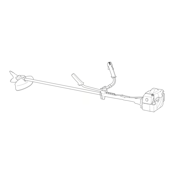
What is what on the brushcutter? 1. Blade 2. Grease filler cap 3. Angle gear 4. Blade guard 5. Shaft 6. Handlebars 7. Throttle 8. Stop switch 9. Throttle trigger lock 10. Suspension for clearing saw 11. Cylinder cover 12. Starter handle 13. -
Page 18: Assembly
Assembling the handlebars (GR2026D/GR2032D) • Remove the screw at the rear of the throttle handle. • Slide on the throttle handle on the right-hand side of the handlebars, (see the diagram). • Align the hole in the throttle handle for the fixing screw with the hole on the handlebars. -
Page 19: Assembly Of The Blade And Trimmer Head
Assembly of the blade and trimmer head It is extremely important that the disc drive’s/support flange’s guide engages correctly in the cutting equipment’s centre hole when assembling the cutting equipment. Cutting equipment assembled incorrectly can result in serious and/or fatal personal injury. -
Page 20: Assembling The Spray Guard And Trimmer Head Auto
Assembling the spray guard and trimmer head Auto 32 (GR2026D/GR2032D) • Fit the guard (A) intended for use with the trimmer head. Secure using the 4 bolts (L) and the support plate (M) as set out in the diagram. • Fit the drive disc (B) on the output axle. -
Page 21: Adjusting The Harness And Clearing Saw
Adjusting the harness and clearing WARNING! When working with the clearing saw it should always be hooked in the harness. If this is not done, you cannot control the clearing saw safely and this can result in injury to yourself or someone else. Never use a harness with a defective quick release catch. -
Page 22: Fuel Handling
• When working at continuous high revs a higher octane rating is recommended. Two-stroke oil • For the best results use JONSERED two-stroke oil, which has been specially developed for clearing saws and chain saws. Mixing ratio 1:50 (2%). • Never use two-stroke oil intended for water cooled outboard motors, so-called outboard motor oil. -
Page 23: Start And Stop
Control before starting For reasons of safety follow these recommendations! • Check the blade to ensure that no cracks have formed at the bottom of the teeth or by the centre hole. The most common reason why cracks are formed is that sharp corners have been formed at the bottom of the teeth while sharpening... -
Page 24: Maintenance
Carburetor Your JONSERED product has been designed and manufactured to specifications that reduce harmful emissions. After your unit has been run 8-10 tanks of fuel the engine has broken in. To ensure that your unit is at peak performance and producing the least amount of harmful... - Page 25 Final setting of the idling speed T Adjust the idling speed with the screw T, If it is necessary to readjust. First turn the idle speed adjusting screw T clockwise until the cutting attachment starts to rotate/ move. Then turn, counter- clockwise until the cutting attachment stops.
-
Page 26: Muffler
Muffler NOTE! Some mufflers are fitted with a catalytic converter. See “Technical data” to see whether you clearing saw is fitted with a catalytic converter. The muffler is designed to dampen the noise level and to direct the exhaust fumes away from the user. -
Page 27: Air Filter
However, before using the machine you should check that the angle gear is filled to 3/4 with grease. Use JONSERED special grease. Normally, the grease does not need to be changed except when the angle gear is repaired. -
Page 28: Sharpening The Clearing Blade
1 mm. – English MAINTENANCE NOTE: Use only JONSERED replacement parts. Use of other brands of replacement parts can cause damage to your unit or injury to the operator or others. Your warranty does not cover damage or liability caused by the use of accessories and/or attachments not specifically recommended by JONSERED. -
Page 29: Technical Data
1/2 idle and 1/2 max. speed. NOTE! Sound pressure at the user’s ear and vibration on the handles are measured with all the machine’s approved cutting equipment fitted. The table indicates the highest and lowest values. TECHNICAL DATA GR 2026D GR 2032D 1,64/26,9 1,88/30,8... - Page 30 Approved accessories GR2026D Centre hole in blades Ø 20 mm Threaded blade axle M10 Grass blade Saw blade Plastic knifes Trimmer head Support cup Approved accessories GR2032D Centre hole in blades Ø 20 mm Threaded blade axle M10 Grass blade Saw blade Plastic knives Trimmer head...
-
Page 31: Emission Control Warranty Statement
If you have any questions regarding your warranty rights and responsibilities, you should contact your nearest authorized servicing dealer or call Jonsered, at Sweden +46 36 14 65 00. WHERE TO GET WARRANTY SERVICE Warranty services or repairs shall be provided at all Jonsered authorized servicing dealers. - Page 32 Auto 32 4,0 m 15 cm ~2,0 m 6 " 6,5 ' 15 cm 6 " – English...
- Page 33 Poly Trim >20mm >20mm 6 Nm X 10 English –...
- Page 34 Tap-N-Go Pro 15 cm 6" “Click” – English 7,5 m ~ 3,7 m 15 cm 6" 15 cm 6"...
- Page 35 Trimmy H II 15 cm 6" 7,5 m ~ 3,7 m 15 cm 6" English –...
- Page 36 Trimmy SII ~ 15 cm – English 35-50 NM 7,0 m 12 cm 5" ~ 3,5 m "Clic"...
- Page 37 Trimmy SII ~ 15 cm ~ 15 cm 502 26 04-01 502 25 56-01 502 25 53-01 729 53 27-71 (x3) 738 21 03-04 502 26 24-01 (x2) 740 43 14-00 502 26 03-01 502 25 52-01 502 26 01-01 735 31 19-00 502 27 07-01 502 26 86-01...
- Page 38 ´*xt=¶5Q¨...
- Page 39 English –...
- Page 40 108 88 42-95 ´*xt=¶5Q¨ 2002W04...