Samsung ML-4550 Service Manual
Digital laser printer ml-4550 series
Hide thumbs
Also See for ML-4550:
- User manual (113 pages) ,
- Service manual (34 pages) ,
- Quick install manual (2 pages)
Table of Contents
Advertisement
Quick Links
SERVICE
DIGITAL LASER PRINT
DIGITAL LASER PRINT
ML-4550 Series
ML-4550 / ML-4551N / ML-4551ND
ML-4551NR / ML-4551NDR
Basic Model : ML-4550
Manual
[The keynote of Product]
- Series Model: ML-4550 / 4551N / 4551ND
- High speed Laser Printer:
Up to 43 ppm in A4 (45 ppm in Letter),
Duplex: 29 ipm (A4); 30 ipm (Letter)
- Resolution: Up to 1200 x 1200 dpi
- Marvell 500Mhz
- Memory: 128 MB (Max. 512 MB)
128, or 256 MB optional memory available.
Use only the Samsung-approved DIMM.
128 MB: ML-MEM150, 256 MB: ML-MEM160
- Option:
ML-4550:500-sheet trays, ethernet 10/100 Base
TX wired LAN, ethernet 10/100 Base
hard disk, duplex unit, DIMM
- Toner cartridge:
Starter: 10K or 20K pages
Consumable: 10K or 20K pages
- Duty cycle: Monthly Up to 150,000 pages
CONTENTS
Advertisement
Table of Contents
Troubleshooting

Related Manuals for Samsung ML-4550


Summary of Contents for Samsung ML-4550
-
Page 1: Service Manual
Manual DIGITAL LASER PRINT CONTENTS [The keynote of Product] - Series Model: ML-4550 / 4551N / 4551ND - High speed Laser Printer: Up to 43 ppm in A4 (45 ppm in Letter), Duplex: 29 ipm (A4); 30 ipm (Letter) - Resolution: Up to 1200 x 1200 dpi - Marvell 500Mhz - Memory: 128 MB (Max. -
Page 2: Table Of Contents
Contents 1. Precautions 1.1 Safety Warning 1.2 Caution for safety 1.2.1 Toxic material 1.2.2 Electric Shock and Fire Safety Precautions 1.2.3 Handling Precautions 1.2.4 Assembly / Disassembly Precautions 1.2.5 Disregarding this warning may cause bodily injury 1.3 ESD Precautions 2. Product Specifications 2.1 Product Overview 2.2 Specifications 2.2.1 General Specifications... - Page 3 Continue... 3.2.6 Print Cartridge 3-10 3.3 Engine H/W Specifications 3-11 3.3.1 ML-4550 (PCL) Main Board 3-11 3.3.2 SMPS & HVPS board 3-16 3.3.3 Engine F/W 3-20 4. Alignment and Adjustments 4.1 How to use EDC (Engine Diagnostic Control) Mode 4.1.1 EDC Setup 4.1.2 Entrance method for EDC...
- Page 4 Continue... 5.8 Main PBA 5.9 Main Drive Ass'y 5.10 DEVE Drive Ass'y 5-10 5.11 Connector PBA 5-11 5.12 Solenoid 5-12 5.13 Rear Cover 5-13 5.14 Cover Left 5-14 5.15 Top Cover 5-15 5.16 Open Cover 5-16 5.17 Inner Cover 5-17 5.18 Fuser Ass'y 5-18 5.19 Duplex Solenoid Ass'y...
- Page 5 Continue... 7.6 Main Motor Assembly 7-16 7.7 Deve Motor Assembly 7-18 7.8 Exit Sorenoid Assembly 7-20 7.9 Cassette Assembly 7-22 7.10 Duplex Unit 7-24 7.11 SCF Unit 7-26 Block diagram 8.1 System Block Diagram Connection Diagram 9.1 Connection Diagram 10. Schematic Diagram 10.1 Main Board 10-1 10.2 DIMM board...
-
Page 6: Precautions
High voltages and lasers inside this product are dangerous. This printer should only be serviced by a suitably trained and qualified service engineer. (2) Use only Samsung replacement parts There are no user serviceable parts inside the printer. Do not make any unauthorized changes or additions to the printer, these could cause the printer to malfunction and create electric shock or fire hazards. -
Page 7: Caution For Safety
Take care not to cut or damage the power cable or plugs when moving the machine. (9) Use caution during thunder or lightening storms. Samsung recommends that this machine be disconnected from the power source when such weather conditions are expected. Do not touch the machine or the power cord if it is still connected to the wall socket in these weather conditions. -
Page 8: Handling Precautions
1.2.4 Assembly / Disassembly Precautions Replace parts carefully, always use Samsung parts. Take care to note the exact location of parts and also cable routing before dismantling any part of the machine. Ensure all parts and cables are replaced correctly. -
Page 9: Disregarding This Warning May Cause Bodily Injury
Failure to do so could cause the printer to tip or fall possibly causing personal injury or damaging the printer. (5) Do not install the printer on a sloping or unstable surface. After installation, double check that the printer is stable. Service Manual Samsung Electronics... -
Page 10: Esd Precautions
9. Minimize bodily motions when handling unpackaged replacement ESDs. Normal motions, such as the brushing together of clothing fabric and lifting one’s foot from a carpeted floor, can generate static electricity sufficient to damage an ESD. Service Manual Samsung Electronics... -
Page 11: Product Specifications
2.1 Product Overview Item Descriptions Remark Basic Model ML-4550 Series Model ML-4550, ML-4551N, ML-4551ND, ML-4551NDG(Kor.) Maket of Sailes Office user Laser printer. (Network for work Group) Specification 43ppm(Ltr. 45ppm), 500MHz Processor, 128MB Memory 10K(initial), 20K(sailes) USB(Hight Speed USB 2.0), Network Option,... -
Page 12: Controller & S/W
Specifications 2.2.2. Controller & S/W ITEM ML-4550 SERIES ML-4550 ML-4551N ML-4551ND Processor Marvell 500Mhz Memory Std. 128 MB Max. 512MB(256+256) PostScript3, PCL6, IBM ProPrinter, EPSON, PDF Direct(only HDD installed) Printer Languages Fonts 45 scalable, 1 bitmap, 136 PostScript 3 fonts, OCR Fonts... -
Page 13: Paper Handling
Specifications 2.2.3. Paper Handling ITEM ML-4550 SERIES ML-4550 ML-4551N ML-4551ND Standard 500-sheet Cassette Tray, 100-sheet Multi Purpose Tray @75g/ Capacity Max. Capacity 2,100 sheets @75g/ Printing Max. Size 216 x 356 mm (8.5" x 14") Min. Size 76 x 127 mm (3.0" x 5.0")(>105g) -
Page 14: Consumables
Specifications 2.2.4. Consumables ITEM ML-4550 SERIES ML-4550 ML-4551N ML-4551ND Toner Black Standard 10K pages @ ISO 19752 standard Coverage High Yield 20K pages @ ISO 19752 standard Coverage Electronic key(CRUM) Life detect Toner remaining volume would be traced via software... -
Page 15: Options
Specifications 2.2.7. Options ITEM ML-4550 SERIES ML-4550 ML-4551N ML-4551ND Memory 128MB/512MB (256MB+256MB) Second Cassette 500 sheet Cassette Tray Third Cassette 500 sheet Cassette Tray Stacker Stapler PostScript Default Wired Network Ethernet 10/100 Base Default Default TX (Internal) Hard Disk 40GB... -
Page 16: Model Comparison Table
Specifications Specifications 2.3 Model Comparison Table Project Lexmark Brother Dell Model Name ML-4550 LJ-4250 T642 HL-8050N W5200N Engine FPOT 8.5 sec 8 sec 8.5 sec 9 sec 8.5 sec Speed(ppm) 43ppm (Ltr. 45ppm) 43ppm (Ltr. 45ppm) 43ppm (Ltr. 45ppm) 34ppm (Ltr. 35ppm) 43ppm (Ltr. - Page 17 Specifications ACCESSORY Item Code Quantity INA-ACCESSORY JC99-01974E 3903-000042 CBF-POWER CORD 6902-000288 BAG PE JC46-00280A S/W APPLICATION-CD JC46-00293A S/W APPLICATION-CD JC68-00690A MANUAL-(CARD)WARRANTY CARD JC68-01579A MANUAL-NETWORK GUIDE JC68-01584A LABEL(P)-BLANK 90*25 Service Manual Samsung Electronics...
-
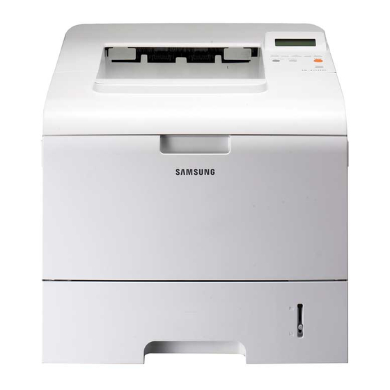
Page 18: Summary Of Product
Summary of Product 3. Summary of Product This chapter describes the functions and operating principal of the main component. 3.1 Printer Components 3.1.1 Front View Service Manual Samsung Electronics... -
Page 19: Rear View
Summary of Product 3.1.2 Rear View Service Manual Samsung Electronics... -
Page 20: Control Panel
Summary of Product 3.1.3 Control Panel The control panel on the top right side of your printer has the display and the nine buttons. 3.1.3.1 Display Service Manual Samsung Electronics... - Page 21 Summary of Product 3.1.3.2 Overview of Control Panel Menus The control panel menus are used to configure the printer for your environment. The control panel provides access to the following menus. Service Manual Samsung Electronics...
-
Page 22: Special Features
• You can print on both sides of the paper to save paper (double-sided printing) if you use the ML-4551ND or install the optional duplex unit in the ML-4550 and ML-4551N. • You can print multiple pages on a single sheet of paper to save paper (N-Up printing). See the Software Section. - Page 23 • Your printer comes with both Parallel and USB interfaces. • You can also use a network interface. The ML-4551N and ML-4551ND come with a built-in network interface, 10/100 Base TX. However, you need to install the optional wired network interface card to the ML-4550. Printer Features The table below lists a general overview of features supported by your printer.
-
Page 24: System Layout
Summary of Product 3.2 System Layout Cassette Duplex Print Cartridge Fuser SMPS & HVPS Board Duplex Solenoid Service Manual Samsung Electronics... -
Page 25: Feeding
9) SCF (Second Cassette Feeder) It is the same method with the main cassette, and the capacity is 500 sheets. It has a separate driving mechanism. It is designed for a common use with a main cassette. Service Manual Samsung Electronics... -
Page 26: Transfer
The controller detects the /HSYNC signal to adjust the vertical line of the image on paper. In other words, after the /HSYNC signal is detected, the image data is sent to the LSU to adjust the left margin on paper. The one side of the polygon mirror is one line for scanning. Service Manual Samsung Electronics... -
Page 27: Print Cartridge
- OPC Drum protecting Shutter : Yes - Classifying device for toner cartridge : ID is classified by CRUM. Cleaning Roller = 1500V, f = 3.0KHz 200V -1.30KV -650V -50V 200V Cleaning Blade +5.0kV <Toner Cartridge Layout> Service Manual 3-10 Samsung Electronics... -
Page 28: Engine H/W Specifications
Summary of Product 3.3 Engine H/W Specifications 3.3.1 ML-4550 (PCL) Main Board The Engine Board and the Controller Board are in one united board, and it is consisted of CPU part and print part in func- tional aspect. The CPU is functioned as the bus control, O/O handling, drivers, and PC interface. The main board sends the Current Image by Video data to the LSU and manages the conduct of Electrophotography for printing. - Page 29 - IEEE 802.3 compliant with 10/100/1000 Mbps full-duplex GbE port - Support GMII,MII and RGMII interface with external PHY/SERDES device Package : 496pins PBGA Power : 1.2V(Core), 3.3V(IO) power operation Speed : 600MHz core(ARM9 Compatible) operation, 200MHz bus operation Service Manual 3-12 Samsung Electronics...
- Page 30 It stores Font List, compressed into Flash memory, on DRAM and uses it as PCL font in case of model for export. - Capacity : 128 Byte(Basic), up to 512Mbyte (User Option) - Type : DDR-II SDRAM 200MHz , 32bit 3.3.1.3 Others The Option PBA can be mounted for supporting the serial communication. Service Manual 3-13 Samsung Electronics...
- Page 31 32 bit up to 200 MHz Mbus DDR1/DDR2 Bridge SDRAM Controller Mbus ? Crossbar extension) 64 bit @ 166 MHz GPPs, PCI- PCI/PCI-X Gigabit USB 2.0 UART x 2, Express 64-bit Ethernet port TWSI, x 1 port port port Flash Service Manual 3-14 Samsung Electronics...
- Page 32 But resistance Rs value of sensing and voltage value of the V reference can be changed by motor driving volt- age value. The motor driving voltage is calculated with the following formula. I = Vref / Rs, wherein Vref is (R1x 5V) / (R1+R2). Service Manual 3-15 Samsung Electronics...
-
Page 33: Smps & Hvps Board
Summary of Product 3.3.2 SMPS & HVPS board Outputs 5V, 24V to supply the power to the main board and Optional Board(SCF, Duplex) (Not ADF Board) SMPS HVPS Service Manual 3-16 Samsung Electronics... - Page 34 - Output Voltage Rising Time : 50 ms Max - Output Voltage Falling Time : 50 ms Max - Output Loading range : 10 M ~ 1000 M - Output Control Signal (BIAS-PWM) : the CPU is HV output when PWM is low. Service Manual 3-17 Samsung Electronics...
- Page 35 AVG : 55 Wh PRINTING 1.0 A 0.14A 2.0 A AVG : 280 Wh Sleep-Mode 0.8A 0.01A 0.4A AVG : 10 Wh • Length of Power Cord : 1830 50mm • Power Switch : Use Service Manual 3-18 Samsung Electronics...
-
Page 36: Fuser Ac Power Control
On the other hand, when the signal is off, the PC1 is off, the voltage is cut off at the gate of Triac, the Triac becomes off, and then the heat lamp is turned off. Triac (THY1) feature :12A, 600V SWITCHING Phototriac Coupler (PC3) Turn On If Current : 15mA 50mA(Design :16mA) High Repetive Peak Off State Voltage : Min 600V Service Manual 3-19 Samsung Electronics... -
Page 37: Engine F/W
AD converter. The voltage value for impressing to the trans- fer roller is decided by the changed value. Each voltage value is controlled according to 3.3.4.2 Timing Chart. Service Manual 3-20 Samsung Electronics... - Page 38 Error Type Description LCD Display Polygon Motor Error Whenthe polygon motor speed doesn t become steady LSU NOT READY Hsync Error The polygon motor speed is steady but the Hsync is not generated HSYNC ERROR Service Manual 3-21 Samsung Electronics...
-
Page 39: Alignment And Adjustments
4. Confirm the message COMPONENT TEST/Press Menu Key is displayed. 5. Press Menu key. 6. Follow a usage for a function you would like to use. * The procedure and content above can be changed according to the situation. Service Manual Samsung Electronics... -
Page 40: Cover Status
Closed displayed. [Closed]/[Open] Fuser Door If the Door is opened, Open message will be Fuser Door displayed and if not, Closed displayed. [Closed]/[Open] • The procedure and content above can be changed according to the situation. Service Manual Samsung Electronics... -
Page 41: Sensor Status
T2 Paper Empty See the message after touching the sensor. T2 Paper Empty T2 Paper Empty [Empty] [Present] T3 Paper Empty See the message after touching the sensor. T3 Paper Empty T3 Paper Empty [Empty] [Present] Service Manual Samsung Electronics... - Page 42 TOP Margin Sen. [Without Paper] [With Paper] DPX Detect Sen See the message after touching the sensor. DPX Detect Sen DPX Detect Sen [Low] [High] * The procedure and content above can be changed according to the situation. Service Manual Samsung Electronics...
-
Page 43: Motor Test
3. Press the Arrow keys until finding a suitable function (Refer to the table below). 4. Press the OK Key , when it is found. 5. Press the OK Key for execution or the Back key for return. Service Manual Samsung Electronics... -
Page 44: Clutch / Sol
The clutch will run or stop. Bypass Clutch [ON] / [OFF] Duplex Sol. The solenoid will run or stop. Duplex Sol. [ON] / [OFF] * The procedure and content above can be changed according to the situation. Service Manual Samsung Electronics... -
Page 45: Fuser Ctrl
3. Press the arrow keys until finding a suitable function. (Refer to the table below) 4. Press the OK Key , when it is found. 5. Press the OK Key for execution or the Cancel key for stop. Service Manual Samsung Electronics... -
Page 46: Deve Control
The bias will have the previously saved value. DEV Vpp Bias [ON] / [OFF] MHV Bias The bias will have the previously saved value. MHV Bias [ON] / [OFF] The lamp will be lighted or not. PTL [ON] / [OFF] Service Manual Samsung Electronics... -
Page 47: Print Test And Option Version
This is the version for Tray4 T4 Version [x.xx] x.xx is version. Duplex Version This is the version for Duplex Duplex Version [x.xx] x.xx is version. * The procedure and content above can be changed according to the situation. Service Manual Samsung Electronics... -
Page 48: Paper Path
Alignment & Adjustments 4.2 Paper Path Cassette Duplex Print Cartridge Fuser SMPS & HVPS Board Duplex Solenoid <Jam 0> <Jam 1> Service Manual 4-10 Samsung Electronics... - Page 49 6) The printing paper that passes the duplex sensor reaches to a feed sensor again and a printing operation is tried over again. - If the printing paper cannot reach to a feed sensor after certain time later, a duplex Jam 2 occurs. Service Manual 4-11 Samsung Electronics...
-
Page 50: Clearing Paper Jams
If the paper does not move when you pull, or if you do not see the paper in this area, check the fuser area around the toner cartridge. 3. Insert the tray 1 into the printer until it snaps into place. Printing automatically resumes. Service Manual 4-12 Samsung Electronics... - Page 51 1. If the paper is not feeding properly, pull the paper out of the printer. 2. Open and close the top cover to resume printing. 3. Open and close the top cover.Printing can be resumed. Service Manual 4-13 Samsung Electronics...
- Page 52 5. Replace the printer cartridge and close the top cover. Printing automatically resumes. Note : If it is difficult to reinstall the printer cartridge, make sure that the guide feed has been flipped back down into position. Service Manual 4-14 Samsung Electronics...
-
Page 53: In The Duplex Unit Area
1. Pull the duplex unit out of the printer. 2. Locate the jammed paper and remove it. 3. Insert the duplex unit into the slot. 4. Open and close the top cover. The printer will resume printing. Service Manual 4-15 Samsung Electronics... - Page 54 Alignment & Adjustments • Duplex jam 1 1. Open the rear cover. 2. Gently pull the jammed paper straight up. 3. Close the rear cover. 4. Open and close the top cover. The printer will resume printing. Service Manual 4-16 Samsung Electronics...
-
Page 55: Sample Pattern
1. On the printer’s front panel, press the Menu button, then press the OK button to select Information. 2. Select Demo Pages, then press the OK button. 3. Select the desired sample page, then press the OK button to print. Service Manual 4-17 Samsung Electronics... -
Page 56: Periodic Defective Image
Heat Roller 126 mm Black spot and image ghost Pressure Roller 126 mm black spot on the backside OPC Drum Transfer Roller Charge Roller Heat Roller Supply Roller Pressure Roller Developing Roller <Rollers Layout> Service Manual 4-18 Samsung Electronics... -
Page 57: Error Messages
CRUM at the DEVE for any polluted areas. Invalid Toner The toner cartridge you have installed is Install a Samsung-genuine toner not for your printer. cartridge, designed for your printer. Load [Size] In [Tray] The paper size specified in the printer Load the correct paper in the tray. - Page 58 Self Diagnostic The engine in your printer is checking Please wait a few minutes. Temperature some problems detected. Sleeping... The printer is in power save mode. When data is received, it switches to on-line automatically. Service Manual 4-20 Samsung Electronics...
- Page 59 Close the tray until it locks into place. Cassette Out [Tray] There is no paper in the tray. Load paper in the tray. Paper Empty Warming Up Your printer is warming up now. Please wait a few minutes. Please Wait... Service Manual 4-21 Samsung Electronics...
-
Page 60: Disassembly And Reassembly
3. Unplug the power cord. 4. Use a flat and clean surface. 5. Replace only with authorized components. 6. Do not force plastic-material components. 7. Make sure all components are in their proper position. Service Manual Samsung Electronics... -
Page 61: Transfer Roller
* Do not grab the Transfer Roller shown in picture (A). It may cause a malfunction due to a foreign object. * Hold the both side of the Transfer Roller shown in picture (B) when replacing it. Transfer Roller Service Manual Samsung Electronics... -
Page 62: Mpf Ass'y
3. Remove the Tray Link from the MP Cover. Tray Link MPF Ass’y 2. Remove two springs from the Knock Up Plate Ass'y. 4. Push the MP Cover and remove it, as shown below. MP Cover Service Manual Samsung Electronics... -
Page 63: Holder Pad Ass'y
3. Remove the Photo Interrupter and the MP Actuator, remove : -MPFAss'y (Refer to the5.3) as shown below. 2. Unplug the connector and remove the three screws, as shown below. Friction Pad MP Actuator Holder Pad Ass’y Service Manual Samsung Electronics... -
Page 64: Retard Ass'y
Disassembly and Reassembly 5.5 Roller Idle ASS'Y 1. Remove the Roller Ass'y, as shown below. 2. Releasse the lock as shown below and take out the retard Ass’y. Roller Idle ASS’Y Service Manual Samsung Electronics... -
Page 65: Feed2 Idle Unit
5.6 Feed2 Idle Unit 1. Before you remove the Feed2 Idle Unit, you should 2. Remove four screws. Then lift the Idle Unit, as shown remove : below. - Holder Pad Ass'y (Refer to the 5.4) Feed2 Idle Unit Service Manual Samsung Electronics... -
Page 66: Cover Right
1. Pull the Cassette out of the printer. 3. Remove two screws and take out the right side, as shown below. Cassette Cover Right 2. Remove the Cover Dummy and Cover Control Box. Cover Control Box Service Manual Samsung Electronics... -
Page 67: Main Pba
3. The Connectors are located, as shown below. Thermistor DPX_SOL Key Panel Toner Cover Open Sensor DEVE Motor Key Panel Main PBA Network SMPS/HVPS Card HDD(Optional) Duplex Port Exit Sensor P1284 Port Main Motor Connector Connector Memory(Optional) Service Manual Samsung Electronics... -
Page 68: Main Drive Ass'y
Main Motor Ass'y. Notice : Make sure the Power Switch is turned off before disassembling the Motor Connector. 3. Remove the Feed1 Gear, as shown below. Main Motor Ass’y Feed1 Gear Service Manual Samsung Electronics... -
Page 69: Deve Drive Ass'y
Ass'y. shown below. DEVE Motor Ass’y Notice : Make sure the Power Switch is turned off before disassembling the Motor Connector. 3. Remove four screws and take out the DEVE Drive Ass'y. DEVE Drive Ass’y Service Manual 5-10 Samsung Electronics... -
Page 70: Connector Pba
: - Cover Right (Refer to the 5.7) Main Solenoid 2. Unplug the all Connectors from the Connector PBA and take it out. Main Clutch MP Solenoid MP Empty Cassette Open S/W Connector Main PBA Service Manual 5-11 Samsung Electronics... -
Page 71: Solenoid
MP Solenoid Main Solenoid Connector PBA *NOTICE : It is not necessary to disassemble the Main Drive Ass'y to remove the MP Solenoid. 3. Remove one screws and take out the MP Solenoid. MP Solenoid Service Manual 5-12 Samsung Electronics... -
Page 72: Rear Cover
Disassembly and Reassembly 5.13 Rear Cover 1. Open the Rear Cover, and then take out the Stopper. 2. Remove the Rear Cover in the direction of arrow Rear Cover ie Stopper Service Manual 5-13 Samsung Electronics... -
Page 73: Cover Left
Disassembly and Reassembly 5.14 Cover Left 1. Pull the Cassette out of the printer. 3. Take out the Cover Left. Cover-Left Cassette 2. Remove two screws and take out the left side. Service Manual 5-14 Samsung Electronics... -
Page 74: Top Cover
2. Open the MPF Ass'y, the Rear Cover, the Open Cover. Open Cover 5. Unlatch the hook and take out the Top Cover. MPF Ass’y 3. Unplug the two Connectors after you remove the three screws from the Main PBA. Key Panel Service Manual 5-15 Samsung Electronics... -
Page 75: Open Cover
1. Before you remove the Open Cover, you should 3. Take out the Open Cover, as shown below. remove: - Top Cover (Refer to the 5.15) 2. Remove two screws and take out the Stopper. Open Cover Stopper Service Manual 5-16 Samsung Electronics... -
Page 76: Inner Cover
5.17 Inner Cover 1. Before you remove the Inner Cover, you should remove: -MPFAss'y (Refer to the5.3) - Top Cover (Refer to the 5.15) 2. Remove two screws and take out the Inner Cover. Inner Cover Service Manual 5-17 Samsung Electronics... -
Page 77: Fuser Ass'y
3. Remove two screws and take the Thermostat out of 5. Remove two screws securing the Fuser Upper Unit the Fuser Ass'y. and remove it, as shown below. Fuser Upper Unit Thermostat Fuser Lower Unit Service Manual 5-18 Samsung Electronics... - Page 78 Cover-Fuser Lower Release Lever R Heat Roller Ass’y 7. Remove two screws and take out the Gear Bracket. Fuser Gear 9. Remove the screw securing the Thermistor and remove it, as shown below. Gear Bracket Thermistor Service Manual 5-19 Samsung Electronics...
-
Page 79: Duplex Solenoid Ass'y
- Top Cover (Refer to the 5.15) 2. Unplug the Duplex Solenoid Harness from the Main Duplex Solenoid PBA. Duplex Solenoid Spring pin 3. Remove three screws and take out the Exit Solenoid Ass'y. Duplex Solenoid Ass’y Service Manual 5-20 Samsung Electronics... -
Page 80: Exit Roller
5. Remove the Duplex Exit Roller as same method. Duplex Exit Roller 3. Remove the Exit Roller and Bearing, as shown below. Exit Roller Rack-Exit Roller Bearing Bearing 6. Release the Duplex Exit Gear, as shown below. Bearing Duplex Exit Gear Service Manual 5-21 Samsung Electronics... -
Page 81: Lsu
- Cover Right (Refer to the 5.7) - Cover Left (Refer to the 5.13) - Top Cover (Refer to the 5.15) 2. Remove the Cover-Frame Exit and unplug the Cover Frame Exit Connector from the Main PBA, as shown below. Service Manual 5-22 Samsung Electronics... -
Page 82: Dc Fan
DC Fan. - Cover Left (Refer to the 5.13) - Cover Rear (Refer to the 5.14) DC Fan 2. Unplug the two Connectors from the Toner Sensor PBA. Stopper Out Full DC Fan Toner Sensor Service Manual 5-23 Samsung Electronics... -
Page 83: Toner Sensor Pba
Cover Open Toner Sensor 5. Remove three screws and take out the LSU Lower Cover. 3. Remove two screws and take out the Toner Sensor PBA. Toner Sensor PBA HV Small LSU Lower Spring Cover Service Manual 5-24 Samsung Electronics... -
Page 84: Regi Ass'y
5. Unplug the Harness, remove the screw and take out the PTL PBA. PTL Upper Terminal 3. Release the lock as shown below and lift up the Gear PTL PBA Cap. PTL PBA Gear Cap Service Manual 5-25 Samsung Electronics... -
Page 85: Mp Pick Up Ass'y
Gear ass’y Bearing 5. Slide the Cam to the right by pulling on the MP Pick Up Shaft, as shown below. 3. Remove the locking equipment rotate the Bearing in the direction of arrow. Idle-Cam Bearing Service Manual 5-26 Samsung Electronics... - Page 86 Disassembly and Reassembly 6. First lift the left side of the Shaft and then remove the 7. Push the Idle toward the ends of Shaft then take out Shaft. the Housing, as shown below. Idle Housing Service Manual 5-27 Samsung Electronics...
-
Page 87: Pick Up & Feed2 Assy
Gear-Pick Up Cam 5. Remove the Actuator as shown below. 3. Release the Pick Up Gear and remove the locking equipment rotate the Bearing in the direction of arrow, Actuator as shown below. Bearing Feed2 Gear Service Manual 5-28 Samsung Electronics... - Page 88 7. Remove two screws securing the Guide-M-Support and remove it. Guide-P-Front Guide-M-Support Feed2 Unit 8. Remove the Feed1 Ass'y, as shown below. Bushing Feed Guide-M-Support E-ring Bearing Shaft Pickup Roller Ass’y Service Manual 5-29 Samsung Electronics...
- Page 89 Disassembly and Reassembly 11. Remove the Roller Unit, as shown below. Pick Up Frame Roller Unit Service Manual 5-30 Samsung Electronics...
-
Page 90: Engine Shield
Ass’y Engine Shield Ass’y 3. Remove the Duplex Guide L, R, as shown below. 5. Remove four screws and take out the Engine PBA out of the Shield. Engine PBA Guide-Duplex L Guide-Duplex R Shield Service Manual 5-31 Samsung Electronics... -
Page 91: Troubleshooting
- Power Module error OP Panel - Main PBA error - LCD Panel error Refer to Indicate Ready or Error Massage Error Massage Power save <Chapter 4.5> Test Print printing Refer to "Solution Quality is of Image Problem" Nomal? Service Manual Samsung Electronics... -
Page 92: The Cause And Solution Of Bad Image
5. If the problems are not solved, replace are on the OPC Drum. the print cartridge. 6. Partly depression or deformation on the 6. Replace the transfer roller if occured as surface of the transfer roller NO.6 Service Manual 6 -2 Samsung Electronics... -
Page 93: Horizontal Black Band
4. In case of 38 mm interval unremovable in 1, take measures as to replace the print cartridge and try to print out. 5. Clean the inside of the set against the paper particles and foreign matter in order not to cause the trouble. Service Manual Samsung Electronics... -
Page 94: Light Image
1 and 2. 3. VD0 signal of the Main PBA is Low state. 4. Replace the LSU Unit or Main PBA. 4. Case back side the cleaning blade of 5. Replace print cartridge. print cartridge. Service Manual Samsung Electronics... -
Page 95: Uneven Density
4. Is the movement(Up and Down) of the transfer roller smooth? 4. Clean the bushing part of the transfer roller. 5. Is the HVPS normal? 5. If the problem is still not solved, replace the print cartridge. Service Manual Samsung Electronics... - Page 96 Select Card stoc or OHP Film on paper type mal paper or transparencies such as OHP, menu from the software application and after Digital Printer higher transfer voltage is required. using returning to the original mode is Digital Printer recommended. Digital Printer Digital Printer Service Manual Samsung Electronics...
- Page 97 2. If the transfer roller is contaminated, stains 2. If the transfer roller is contaminated, run Digital Printer on the face of page will occur. OPC Cleaning Mode Print 2 or 3 times. And perform Self-Test 2 or 3 times to remove contamination. Service Manual Samsung Electronics...
-
Page 98: Stains On The Back Of Page
2. Perform the engine self test using EDC Mode to check if the Solenoid is normal. 3. If not solved by the above directions 1-2, Replace the engine board. 4. Turn the power off, delete the data of PC and try printing again. Service Manual Samsung Electronics... -
Page 99: The Cause And Solution Of The Bad Discharge
4. Replace the Main PBA and/or Sensor. whether the assembly slot between shaft-pickup and housing-pickup opens or is broken away. 5. If the paper feeds into the printer and Jam 0 occurs, perform EDC Mode to check feed-sensor of the engine board. Service Manual Samsung Electronics... - Page 100 3. Remove the jammed paper after disas- sembling the fuser : Clean the surface of the pressure roller with dry gauze. • Remove the toner particles stained on the rib. • Check the assemblage and perfor- mance of the exit. Service Manual 6-10 Samsung Electronics...
- Page 101 If it is worn or defective, replace it. 3. Check an operation of a feed roller and a registration roller. If they are worn or defective replace them. Service Manual 6-11 Samsung Electronics...
- Page 102 3. Clean the surface of the heat roller with IPA or water 4. Check the warp or separation of the print claw and the holder plate claw, and then manage it. Service Manual 6-12 Samsung Electronics...
-
Page 103: Paper Rolled On The Opc Drum
2. How to remove the rolled paper in the OPC. • Remove the paper while turning the OPC against the ongoing direction. • Clean fingerprints on the OPC softly with soft cloth dampened with tissue. Service Manual 6-13 Samsung Electronics... -
Page 104: The Cause And Solution Of The Malfunction
2. Check whether the LSU motor is rotating or not. 2. Replace a LSU. 3. Check the HSYNC signal. 3. Replace a main board if the same error occurs again after replacing a LSU. Service Manual 6-14 Samsung Electronics... -
Page 105: Paper Empty
1. Bending or deformation of the actuator of the paper sen- 1. Replace the defective actuator. sor. 2. The function of the engine board is defective 2. Replace the empty sensor PBA. 3. Check the connector and harness. Service Manual 6-15 Samsung Electronics... -
Page 106: Paper Empty Without Indication
2. Check the main board 2. Check the insertion of the cover open S/W connect. 3. Check the cover open board. 3. Replace the main board or cover open board. 4. Check the harness and connection. Service Manual 6-16 Samsung Electronics... - Page 107 1. Check the cover open circuit on the main board. 1. Check the insertion of the cover open S/W connect. 2. Check the cover open board. 2. Replace the main control board or cover open board. Service Manual 6-17 Samsung Electronics...
-
Page 108: Defective Motor Operation
1. Check if the power input and SMPS output are normal. 1. Replace the SMPS. 2. Check the inferiority of LED-Panel or LDC window on the 2. Replace the control board. front-cover if the OP panel does not appear after normal warming-up. Service Manual 6-18 Samsung Electronics... -
Page 109: Vertical Line Getting Curved
1. If the supply of +24v is unstable in the main control board 1. Replace LSU. linking with LSU, check drive by EDC mode: LSU check. 2. Replace the toner sensor PBA. 2. Chect the deve PBA in the print cartridge. 2. Replace the main PBA. Service Manual 6-19 Samsung Electronics... -
Page 110: Maintaining The Toner Cartridge
Following the key formation at the panel, note the toner remaining level on the cartridge information after taking out the configuration sheet. In other way to check, follow the TECH mode and out put the cartridge information. The display shows the percentage of the remaining toner. Service Manual 6-20 Samsung Electronics... -
Page 111: Redistributing Toner Cartridge
3. Thoroughly shake the cartridge 5 or 6 times to distrib- ute the toner evenly inside the cartridge. Note : If toner gets on your clothing, wipe it off with a dry cloth and wash clothing in cold water. Hot water sets toner into fabric. Service Manual 6-21 Samsung Electronics... -
Page 112: Replacing The Toner Cartridge
5. Remove the flexible plastic holder out of the toner cartridge. Caution : Do not use sharp objects, such as a knife or scissors, to open the toner cartridge package. They might scratch the drum of the cartridge. Service Manual 6-22 Samsung Electronics... - Page 113 Save the box and the plastic bag grooves within the printer will guide the cartridge into for shipping. the correct position until it locks into place completely. 8. Close the top cover. Make sure that the cover is securely closed. Service Manual 6-23 Samsung Electronics...
- Page 114 A toner cartridge is not installed. Install a toner cartridge. Invalid Toner The toner cartridge you have Install a Samsung -genuine toner cartridge ,designed for your printer. installed is not for your printer. Toner Low The toner cartridge is almost empty.
-
Page 115: The Cause And Solutions Of Bad Environment Of The Software
4. If the scanner needs to be connected to the printer, 4. Check if the printer cable is directly connected to periph- first the remove the scanner from the PC to see if the eral devices printer is properly working alone. Service Manual 6-25 Samsung Electronics... - Page 116 Turn the PC and printer off, and reboot the system to print again. If not solved, double-click the printer in my computer If the regular fonts are not printed this time again. the cable must be defective so replace the cable with new one. Service Manual 6-26 Samsung Electronics...
-
Page 117: Abnormal Printing
3. Delete the unnecessary files to secure enough (The printing job sometimes stops or due to insufficient space of the hard disk and start printing job again. virtual memory, but it actually comes from the insuffi- cient space of the hard disk.) Service Manual 6-27 Samsung Electronics... -
Page 118: Spool Error
Before choosing the document, the menu is still inactive. Or put the document out of the list and repeat the routine as in the above or finish the spool manager. Service Manual 6-28 Samsung Electronics... - Page 119 - Power Module error OP Panel - Main PBA error - LCD Panel error Refer to Indicate Ready or Error Massage Error Massage Power save <Chapter 4.5> Test Print printing Refer to "Solution Quality is of Image Problem" Nomal? Service Manual Samsung Electronics...
-
Page 120: Vertical White Line
5. If the problems are not solved, replace are on the OPC Drum. the print cartridge. 6. Partly depression or deformation on the 6. Replace the transfer roller if occured as surface of the transfer roller NO.6 Service Manual 6 -2 Samsung Electronics... - Page 121 4. In case of 38 mm interval unremovable in 1, take measures as to replace the print cartridge and try to print out. 5. Clean the inside of the set against the paper particles and foreign matter in order not to cause the trouble. Service Manual Samsung Electronics...
- Page 122 1 and 2. 3. VD0 signal of the Main PBA is Low state. 4. Replace the LSU Unit or Main PBA. 4. Case back side the cleaning blade of 5. Replace print cartridge. print cartridge. Service Manual Samsung Electronics...
- Page 123 4. Is the movement(Up and Down) of the transfer roller smooth? 4. Clean the bushing part of the transfer roller. 5. Is the HVPS normal? 5. If the problem is still not solved, replace the print cartridge. Service Manual Samsung Electronics...
- Page 124 Select Card stoc or OHP Film on paper type mal paper or transparencies such as OHP, menu from the software application and after Digital Printer higher transfer voltage is required. using returning to the original mode is Digital Printer recommended. Digital Printer Digital Printer Service Manual Samsung Electronics...
- Page 125 2. If the transfer roller is contaminated, stains 2. If the transfer roller is contaminated, run Digital Printer on the face of page will occur. OPC Cleaning Mode Print 2 or 3 times. And perform Self-Test 2 or 3 times to remove contamination. Service Manual Samsung Electronics...
- Page 126 2. Perform the engine self test using EDC Mode to check if the Solenoid is normal. 3. If not solved by the above directions 1-2, Replace the engine board. 4. Turn the power off, delete the data of PC and try printing again. Service Manual Samsung Electronics...
-
Page 127: Wrong Print Position
4. Replace the Main PBA and/or Sensor. whether the assembly slot between shaft-pickup and housing-pickup opens or is broken away. 5. If the paper feeds into the printer and Jam 0 occurs, perform EDC Mode to check feed-sensor of the engine board. Service Manual Samsung Electronics... - Page 128 3. Remove the jammed paper after disas- sembling the fuser : Clean the surface of the pressure roller with dry gauze. • Remove the toner particles stained on the rib. • Check the assemblage and perfor- mance of the exit. Service Manual 6-10 Samsung Electronics...
- Page 129 If it is worn or defective, replace it. 3. Check an operation of a feed roller and a registration roller. If they are worn or defective replace them. Service Manual 6-11 Samsung Electronics...
- Page 130 3. Clean the surface of the heat roller with IPA or water 4. Check the warp or separation of the print claw and the holder plate claw, and then manage it. Service Manual 6-12 Samsung Electronics...
- Page 131 2. How to remove the rolled paper in the OPC. • Remove the paper while turning the OPC against the ongoing direction. • Clean fingerprints on the OPC softly with soft cloth dampened with tissue. Service Manual 6-13 Samsung Electronics...
-
Page 132: Fuser Error
2. Check whether the LSU motor is rotating or not. 2. Replace a LSU. 3. Check the HSYNC signal. 3. Replace a main board if the same error occurs again after replacing a LSU. Service Manual 6-14 Samsung Electronics... - Page 133 1. Bending or deformation of the actuator of the paper sen- 1. Replace the defective actuator. sor. 2. The function of the engine board is defective 2. Replace the empty sensor PBA. 3. Check the connector and harness. Service Manual 6-15 Samsung Electronics...
- Page 134 2. Check the main board 2. Check the insertion of the cover open S/W connect. 3. Check the cover open board. 3. Replace the main board or cover open board. 4. Check the harness and connection. Service Manual 6-16 Samsung Electronics...
- Page 135 1. Check the cover open circuit on the main board. 1. Check the insertion of the cover open S/W connect. 2. Check the cover open board. 2. Replace the main control board or cover open board. Service Manual 6-17 Samsung Electronics...
- Page 136 1. Check if the power input and SMPS output are normal. 1. Replace the SMPS. 2. Check the inferiority of LED-Panel or LDC window on the 2. Replace the control board. front-cover if the OP panel does not appear after normal warming-up. Service Manual 6-18 Samsung Electronics...
- Page 137 1. If the supply of +24v is unstable in the main control board 1. Replace LSU. linking with LSU, check drive by EDC mode: LSU check. 2. Replace the toner sensor PBA. 2. Chect the deve PBA in the print cartridge. 2. Replace the main PBA. Service Manual 6-19 Samsung Electronics...
- Page 138 Following the key formation at the panel, note the toner remaining level on the cartridge information after taking out the configuration sheet. In other way to check, follow the TECH mode and out put the cartridge information. The display shows the percentage of the remaining toner. Service Manual 6-20 Samsung Electronics...
- Page 139 3. Thoroughly shake the cartridge 5 or 6 times to distrib- ute the toner evenly inside the cartridge. Note : If toner gets on your clothing, wipe it off with a dry cloth and wash clothing in cold water. Hot water sets toner into fabric. Service Manual 6-21 Samsung Electronics...
- Page 140 5. Remove the flexible plastic holder out of the toner cartridge. Caution : Do not use sharp objects, such as a knife or scissors, to open the toner cartridge package. They might scratch the drum of the cartridge. Service Manual 6-22 Samsung Electronics...
- Page 141 Save the box and the plastic bag grooves within the printer will guide the cartridge into for shipping. the correct position until it locks into place completely. 8. Close the top cover. Make sure that the cover is securely closed. Service Manual 6-23 Samsung Electronics...
- Page 142 A toner cartridge is not installed. Install a toner cartridge. Invalid Toner The toner cartridge you have Install a Samsung -genuine toner cartridge ,designed for your printer. installed is not for your printer. Toner Low The toner cartridge is almost empty.
- Page 143 4. If the scanner needs to be connected to the printer, 4. Check if the printer cable is directly connected to periph- first the remove the scanner from the PC to see if the eral devices printer is properly working alone. Service Manual 6-25 Samsung Electronics...
- Page 144 Turn the PC and printer off, and reboot the system to print again. If not solved, double-click the printer in my computer If the regular fonts are not printed this time again. the cable must be defective so replace the cable with new one. Service Manual 6-26 Samsung Electronics...
- Page 145 3. Delete the unnecessary files to secure enough (The printing job sometimes stops or due to insufficient space of the hard disk and start printing job again. virtual memory, but it actually comes from the insuffi- cient space of the hard disk.) Service Manual 6-27 Samsung Electronics...
- Page 146 Before choosing the document, the menu is still inactive. Or put the document out of the list and repeat the routine as in the above or finish the spool manager. Service Manual 6-28 Samsung Electronics...
-
Page 147: Exploded Views & Parts List
Exploded Views & Parts List 7. Exploded Views and Parts List (ML-4550 Series) Contents 7.1 Main Assembly 7.2 Cover Assembly Frame Assembly 7.4 Fuser Unit 7.5 REGI Assembly Main Motor Assembly 7.7 Deve Motor Assembly 7.8 Exit Sorenoid Assembly 7.9 Cassette Assembly 7.10 Duplex Unit... -
Page 148: Main Assembly
Exploded Views & Parts List 7.1 Main Assembly (Network only) 39-2 39-1 20-1 20-3 20-2 21-3 21-2 21-1 Service Manual Samsung Electronics... - Page 149 Exploded Views & Parts List Service Parts List(ML-4551N/ND/NDR) Service(SA:service available, SNA:service not available) Drawer# SEC_Code Description Location QT'Y Service Remark 7.1-0 ML-4550 MONO LASER,43PPM/A4 7.1-0 ML-4551N MONO LASER,43PPM/A4,NETWORK 7.1-0 ML-4551ND MONO LASER,43PPM/A4,NETWORK,DUPLEX 7.1-1 JC96-04004A ELA UNIT-FRAME BASE 110V 7.1-1 JC96-04004B...
- Page 150 JC92-01839A PBA-ERASE_LAMP Z4424 7.1-37 JC96-03412C ELA UNIT-DUPLEX Z6089 7.1-37 JC96-03412E ELA UNIT-DUPLEX Z6089 ML-4551NDR 7.1-38 JC31-00050A Z4425 7.1-39 JC96-03586A ELA HOU-EMBEDDED_MAC Z4426 7.1-39-1 JC92-01700B PBA SUB-NPC_PRT Z4427 BRACKET-_M_NPC 7.1-39-2 JC61-00809A B0005 CBF-POWER CORD Replacement Replacement BOX-MAIN Service Manual Samsung Electronics...
-
Page 151: Cover Assembly
Exploded Views & Parts List Exploded Views & Parts List 7.2 Cover Assembly 1-12 1-17 1-13 1-10 1-11 1-16 1-15 1-14 1-18 6-10 7 (N/A : ML-4551ND) Service Manual Samsung Electronics... - Page 152 Exploded Views & Parts List Service(SA:service available, SNA:service not available) Drawer# SEC_Code Description Location QT'Y Service Remark ELA HOU BASE-HOUSING 7.2-0 JC96-04064A Z4399 ML-4550 7.2-0 JC96-04064B ELA HOU BASE-HOUSING Z4399 ML-4551ND 7.2-0 JC96-04064E ELA HOU BASE-HOUSING Z4399 ML-4551NDR 7.2-0 JC96-04064C...
- Page 153 Exploded Views & Parts List 7.3 Frame Assembly(1/2) Service Manual Samsung Electronics...
-
Page 154: Frame Assembly
49-9 49-1 50-7 49-10 49-13 50-1 49-11 49-9 49-10 50-2 49-12 59-11 60-6 59-9 60-6-3 60-6-1 59-5 60-1 59-6 60-6-2 59-10 59-5-1 59-8 60-4 59-5-2 59-7 59-4 60-5 60-2 59-2-1 60-3 59-2-2 59-1 59-2-3 59-3 59-2 Service Manual Samsung Electronics... - Page 155 JC61-40001A FOOT-ML80 F0003 7.3-40 JC72-01355A PMO-REMOVE_LOCK_CST L6040 7.3-43 JC72-41191B PMO-BEARING SHAFT P0032 7.3-47 JC96-03960A ELA HOU-FRAME_LSU_LO Z4463 7.3-47-1 JC61-01732A FRAME-PART_UPPER Z4464 7.3-47-2 JC92-01807A PBA SUB-TONER_SENSOR Z4465 7.3-47-3 JC65-00004A TERMINAL-P_DEVE T2175 7.3-47-4 JC92-01730A PBA SUB-COVER OEPN M0443 Service Manual Samsung Electronics...
- Page 156 Z4497 7.3-71 JC67-00036A CAP-M-WIRE PTL LOWER C1015 7.3-72 JC65-00001A TERMINAL-P_PTL K4276 7.3-73 JC92-01516A PBA SUB-PTL2 M0411 PBA SUB-EXIT SENSOR 7.3-76 JC92-01512B M0445 PBA SUB-FUSER SW 7.3-77 JC92-01261C M0447 7.3-78 JC61-01218A GUIDE-M-FRONT G0442 7.3-79 JC65-00010B TERMINAL-GUIDE_FRONT Service Manual 7-10 Samsung Electronics...
- Page 157 MEA UNIT-TERMINAL:TR Z4500 7.3-93 JC39-00625A HARNESS-HVPS Z4501 7.3-94 JC70-00332A IPR-P_GROUND OPC O0020 7.3-95 JC92-01831A PBA SUB-EMPTY Z4502 7.3-96 JC39-00620A HARNESS-SENSOR Z4503 7.3-97 JC92-01262C PBA SUB-FEED SENSOR M0446 7.3-98 JC67-00098A CAP-M_HV Z4504 7.3-99 JC67-00097A CAP-M_SENSOR_FEED Z4505 Service Manual 7-11 Samsung Electronics...
-
Page 158: Fuser Unit
Exploded Views & Parts List 7.4 Fuser Unit 1-14 1-14 1-26 1-11 1-15 1-10 1-12 1-18 1-27 1-28 1-21 1-29 1-19 1-19 1-17 1-22 1-16 1-20 1-17 1-13 1-24 1-23 3-15 3-16 3-14 3-10 3-13 3-11 3-12 3-14 Service Manual 7-12 Samsung Electronics... - Page 159 SPRING ETC-ACTUATOR Z4132 7.4-3-12 JC72-01358A PMO-ACTUATOR EXIT Z4536 7.4-3-13 JC67-00103A CAP-M-ACTUATOR Z4537 7.4-3-14 6003-000196 SCREW-TAPTITE Z4397 7.4-4 JC97-02631A MEA UNIT-FUSER_GU_R Z4539 7.4-4-1 JC61-01226B GUIDE-M_REAR Z4540 7.4-4-2 JC72-00382A PMO-BUSHING TX Z4606 7.4-4-6 JC61-01549A HOLDER-M REAR_LEVER Z4542 Service Manual 7-13 Samsung Electronics...
-
Page 160: Regi Assembly
Exploded Views & Parts List 7.5 REGI Assembly Service Manual 7-14 Samsung Electronics... - Page 161 JC72-00998A PMO-ACTUATOR REGISHUTTER P0030 7.5-9 JC61-00670A GUIDE-P_REGI PLATE G2081 7.5-10 JC75-00095A MEC-BRUSH ANTISTATIC M0022 7.5-11 JC61-00669A BUSH-M-ROLLER REGI U B0029 7.5-12 JC66-00420A GEAR-REGI Z25 G0415 7.5-13 JC61-00669A BUSH-M-ROLLER REGI U B0029 7.5-14 6107-001155 SPRING-ES Z4544 Service Manual 7-15 Samsung Electronics...
-
Page 162: Main Motor Assembly
Exploded Views & Parts List Exploded Views & Parts List 7.6 Main Motor Assembly Service Manual 7-16 Samsung Electronics... - Page 163 GEAR-M-FUSER IDLE 1 Z4549 7.6-8 JC66-00865A GEAR-M-RDCN REGI Z4550 7.6-9 JC66-00866A GEAR-M-RDCN PICK UP Z4551 7.6-10 JC66-00861A GEAR-M-MP DRV Z4552 7.6-11 JC66-00862A GEAR-M-FEED DRV Z4553 7.6-12 JC66-00873A GEAR-M-RDCN MP Z4554 7.6-14 JC66-00863A GEAR-M-PICK UP DRV Z4555 Service Manual 7-17 Samsung Electronics...
-
Page 164: Deve Motor Assembly
Exploded Views & Parts List 7.7 Deve Motor Assembly Service Manual 7-18 Samsung Electronics... - Page 165 Remark ELA UNIT-DEVE MOTOR 7.7-0 JC96-03408A K3057 7.7-1 JC31-00039A MOTOR DC-BLDC DEVE B5012 7.7-2 JC61-01201A BRACKET-P-DEVE Z4556 7.7-3 JC61-01203A BRACKET-P-SWING Z4557 7.7-4 JC66-00915A SHAFT-SWING DEVE Z4558 7.7-5 JC66-00871A GEAR-M-RDCN DEVE Z4559 7.7-6 JC66-00857A GEAR-M-SWING Z4560 Service Manual 7-19 Samsung Electronics...
- Page 166 Exploded Views & Parts List 7.8 Duplex Sorenoid Assembly Service Manual 7-20 Samsung Electronics...
- Page 167 JC66-40911A GEAR-DP,IDLE G0198 7.8-5 JC66-00100A GEAR-6 Z4562 7.8-6 6031-001255 WASHER-PLAIN W0004 7.8-8 JC33-00008A SOLENOID-DUPLEX S8014 7.8-9 JC61-01202A BRACKET-P-LINK SWING Z4563 7.8-10 JC66-00855A GEAR-M-SWING DUPLEX Z4564 7.8-11 JC66-00856A GEAR-M-RDCN EXIT Z4565 7.8-12 JC66-00916A SHAFT-SWING DUPLEX Z4566 Service Manual 7-21 Samsung Electronics...
-
Page 168: Cassette Assembly
Exploded Views & Parts List 7.9 Cassette Assembly Service Manual 7-22 Samsung Electronics... - Page 169 HOLDER-M-PAD_HOUSING JC61-01724A 7.9-22 GUIDE-PAPER JC64-00268A 7.9-23 SHUTTER-PATH 7.9-24 JC61-00455A SPRING ETC-PLATE K/UP Z4228 7.9-25 JC61-01245A PLATE-P-KNOCK UP Z4570 JC73-00141A R0020 7.9-26 RPR-PAD CASSETTE JC61-01221B Z4568 7.9-27 GUIDE-M_HANDLE JC61-01221C Z4568 ML-4551NDR 7.9-27 GUIDE-M_HANDLE JC68-01552A 7.9-28 LABEL(R)-CASSETTE Service Manual 7-23 Samsung Electronics...
-
Page 170: Duplex Unit
Exploded Views & Parts List 7.10 Duplex Unit Service Manual 7-24 Samsung Electronics... - Page 171 PCT-SILP WASHER 7.10-27 JC61-01277A SPRING ETC-DUP Z4553 7.10-28 JC66-00900A PULLEY-M-18-DUMMY_DUP D2119 7.10-29 JC66-00899A PULLEY-18_DUP D2118 7.10-30 JC61-00665A BUSH-M-FEED, DUP F6042 7.10-32 JC66-00901A ROLLER-FEED_DUP D2145 7.10-33 6044-000107 RING-C Z4396 7.10-34 JC70-00457A ICT-STUD PAPER GUIDE, DP G2098 Service Manual 7-25 Samsung Electronics...
-
Page 172: Scf Unit
Exploded Views & Parts List 7.11 SCF Unit Service Manual 7-26 Samsung Electronics... - Page 173 SPRING ETC-PLATE K/UP Z4228 7.11-25 JC61-01245A PLATE-P-KNOCK UP Z4570 7.11-26 JC73-00141A RPR-PAD CASSETTE R0020 7.11-27 JC61-01221B GUIDE-M_HANDLE Z4568 7.11-27 JC61-01221C GUIDE-M_HANDLE Z4568 ML-4551NDR 7.11-28 JC68-01552A LABEL(R)-CASSETTE 7.11-30 JC61-00064A SPRING ETC-CLAW O1032 7.11-32 JC63-01206A GROUND-CASSETTE Z6101 Service Manual 7-27 Samsung Electronics...
-
Page 174: Block Diagram
Block diagram 8. Block Diagram 8.1 System Block Diagram Service Manual Samsung Electronics... - Page 175 Block diagram Service Manual Samsung Electronics...
- Page 176 MP_EMPTY 3.3V CASSETTE_DETECT 7 24VS DGND DGND Temp1 nDEV_MOT_RDY DEV_MOT_CLK nDEV_MOT_ON 3.3V DEV_MOT_DIR PANEL_TXD PANEL_RXD nRSTOUT DGND DGND 3.3V P_EXIT 3.3V 24VS nTRST 3.3V DEBUG_RXD nRESET DEBUG_TXD DGND 3.3V 3.3V 24VS Duplex_RXD nDuplex_Detect LSU_SAVE Duplex_TXD LSU_5V Service Manual Samsung Electronics...
- Page 177 Connection Diagram Service Manual...
-
Page 178: Connection Diagram
Connection Diagram Service Manual Samsung Electronics... -
Page 179: Reference Information
Standard : "-" type, "+" type (M3 long, M3 short, M2 long, M2 short). • Software (Driver) installation CD ROM • Tweezers Standard : For general home use, small type. • Cotton Swab Standard : For general home use, for medical service. Service Manual 11-1 Samsung Electronics... -
Page 180: Acronyms And Abbreviations
Host Based Printing Hard Disk Drive High temperature and high marshy place high voltage HVPS High Voltage Power Supply interface Input and Output integrated circuit Intelligent Drive electronics or Imbedded Drive Electronics Service Manual 11-2 Samsung Electronics... - Page 181 Quick Printer Initiating Device Q ty quantity Random Access Memory Read Only Memory Second Cassette Feeder SMPS Switching Mode Power Supply SPGP Samsung Printer Graphic Processor Samsung Printer Language Spool Simultaneous Peripheral Operation Online switch sync synchronous or synchronization Universal Serial Bus WECA...
-
Page 182: Select A Location For The Printer
• Provide the proper environment : - A firm, level surface - Away from the direct airflow of air conditioners, heaters, or ventilators - Free of extreme fluctuations of temperature, sunlight, or humidity - Clean, dry, and free of dust Service Manual 11-4 Samsung Electronics... -
Page 183: Sample Tests Patterns
The life of the toner cartridge, developer cartridge and printing speed are measured with the pattern shown below. The A4 ISO 19752 standard pattern samples are reproduced reduced to 70% of the actual A4 size. Service Manual 11-5 Samsung Electronics... - Page 184 Normal NPC &No Packet RJ-45 Jack Active LED Off/On maintenance NPC Initial inferiority Link LED On The link LED On OPC,Normally linked (Red:Wireless,Green:Wire,Orange:Wire) Active LED(Green) Link LED Off Link LED off NPC,Link Inferiority Link LED (Red/Green/Orange) Service Manual 11-6 Samsung Electronics...
- Page 185 ELECTRONICS Samsung Electronics Co.,Ltd. Mar. 2006 * This service manual is a property of Samsung Electronics Co., Ltd. Printed in Korea. Any unauthorized use of Manual can be punished under applicable VERSION NO. : 1.00 CODE : JC-0168R international and/or domestic law.