Table of Contents
Advertisement
Advertisement
Table of Contents

Related Manuals for MSI MS-7551


Summary of Contents for MSI MS-7551
- Page 1 KA790GX/ KA780G/ KA780V Series MS-7551 (v1.X) Mainboard G52-75511X1...
-
Page 2: Trademarks
Alternatively, please try the following help resources for further guidance. Visit the MSI website for FAQ, technical guide, BIOS updates, driver updates, an d ot h er i n f orm at i on: h t t p: / / g l o ba l . -
Page 3: Safety Instructions
Safety Instructions Always read the safety instructions carefully. Keep this User’s Manual for future reference. Keep this equipment away from humidity. Lay this equipment on a reliable flat surface before setting it up. The openings on the enclosure are for air convection hence protects the equip- ment from overheating. -
Page 4: Fcc-B Radio Frequency Interference Statement
VOIR LA NOTICE D’INSTALLATION AVANT DE RACCORDER AU RESEAU. Micro-Star International MS-7551 This device complies with Part 15 of the FCC Rules. Operation is subject to the following two conditions: (1) this device may not cause harmful interference, and (2) this device must accept any interference received, including interference that may cause undesired operation. -
Page 5: Weee (Waste Electrical And Electronic Equipment) Statement
WEEE (Waste Electrical and Electronic Equipment) Statement... -
Page 8: Table Of Contents
CONTENTS Copyright Notice ......................ii Trademarks ........................ii Revision History ......................ii Technical Support ......................ii Safety Instructions ......................iii FCC-B Radio Frequency Interference Statement ............iv W EEE (Waste Electrical and Electronic Equipment) Statement ........v Chapter 1. Getting Started ..................1-1 Mainboard Specifications ................... - Page 9 Appendix A Realtek Audio ................... A-1 Installing the Realtek HD Audio Driver ..............A-2 Software Configuration ..................A-4 Hardware Setup ....................A-19 Appendix B Dual Core Center ................B-1 Activating Dual Core Center ................B-2 Main ........................B-3 DOT (Dynamic OverClocking) ................B-5 Clock ........................
-
Page 10: Chapter 1. Getting Started
Getting Started Chapter 1 Getting Started T hank you f or c hoosing the KA790GX/ KA780G / KA780V Series (MS-7551 v1.X) ATX mainboards. The KA790GX/ KA780G/ KA780V Series mainboards are ® based on AM D RS780D/ RS780/ RS780C & SB700/ SB750 chipsets for optimal system efficiency. -
Page 11: Mainboard Specifications
Phenom FX/X4/X3/X2, Athlon 64 FX/X2, Sempron in the Socket AM2+/ AM2 package - Supports 4 pin CPU Fan Pin-Header with Fan Speed Control (For the latest information about CPU, please visit http://global.msi.com.tw/index.php?func=cpuform) Supported FSB - HyperTransport 3.0 supports speed up to 2600 MHz Chipset ®... - Page 12 Getting Started Connectors Back panel - 1 PS/2 port for mouse or keyboard (auto detection) - 1 VGA port - 1 DVI-D port - 1 Optical SPDIF-out jack - 1 HDMI port - 6 USB 2.0 ports - 1 ESATA port - 1 LAN jack - 6 flexible audio jacks On-Board Pinheaders/ buttons/ switch...
-
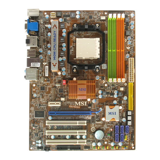
Page 13: Mainboard Layout
PCI_E1 POWER1 SB700 / SB750 (Optional) Chip RESET 1 PCI_E2 (Optional) CLR_CMOS1 (Optional) PCI 1 PCI 2 BATT Codec PCI 3 JBAT1 JFP2 JAUD1 JCD1 JCOM1 JUSB1 JUSB2 JUSB3 JFP1 FDD 1 KA790GX/ KA780G/ KA780V Series (MS-7551 v1.X) ATX Mainboard... -
Page 14: Packing Checklist
Getting Started Packing Checklist Back IO Shield MSI Driver/Utility CD MSI motherboard Power Cable SATA Cable IDE Cable User’s Guide * The pictures are for reference only and may vary from the packing contents of the product you purchased. -
Page 15: Chapter 2. Hardware Setup
Hardware Setup Chapter 2 Hardware Setup This chapter provides you with the information about hardware setup procedures. While doing the installation, be careful in holding the components and follow the installation procedures. For some components, if you install in the wrong orientation, the components will not work properly. -
Page 16: Quick Components Guide
M S-7551 M ainboard Quick Components Guide OCSWITCH1, p.2-20 CPU, SYSFAN2, p.2-3 p.2-13 JPWR1, CPUFAN1, p.2-8 p.2-13 DDR2, p.2-6 Back Panel I/O, p.2-9 SYSFAN1, p.2-13 JPWR2, p.2-8 IDE1, p.2-11 JCI1, p.2-12 PCI Express POWER/ RESET/ slots, p.2-21 CLR_CMOS1,p.2-19 SATA1~5, p.2-12 JTPM1, p.2-14 PCI Slots, JFP2, p.2-16... -
Page 17: Cpu (Central Processing Unit)
If you do not have the heat sink and cooling fan, contact your dealer to purchase and install them before turning on the computer. For the latest information about CPU, please visit http://global.msi.com.tw/index.php? func=cpuform Important Overheating Overheating will seriously damage the CPU and system. - Page 18 M S-7551 M ainboard CPU Installation Procedures for Socket AM2+/ AM2 1. Please turn off the power and unplug the power cord before Open the lever installing the CPU. Sliding the plate 90 degree 2. Pull the lever s ideways away from the socket.
- Page 19 Hardware Setup Installing AMD Socket AM2+/AM2 CPU Cooler Set W hen you are installing the CPU, make sure the CPU has a heat sink and a cooling fan attached on the top to prevent overheating. If you do not have the heat sink and cooling fan, contact your dealer to purchase and install them before turning on the computer.
-
Page 20: Memory
M S-7551 M ainboard Memory These DIMM slots are used for installing memory modules. For more information on compatible components, please visit http://global.msi.com. tw/index.php?func=testreport DDR2 240-pin, 1.8V 56x2=112 pin 64x2=128 pin Dual-Channel Memory Population Rules In Dual-Channel mode, the memory modules can transmit and receive data with two data bus lines simultaneously. -
Page 21: Installing Memory Modules
Hardware Setup Installing Memory Modules 1. The memory module has only one notch on the center and will only fit in the right orientation. 2. Insert the memory module vertically into the DIMM slot. Then push it in until the golden finger on the memory module is deeply inserted in the DIMM slot. -
Page 22: Power Supply
M S-7551 M ainboard Power Supply ATX 24-Pin Power Connector: JPWR2 This connector allows you to connect an ATX 24-pin power supply. To connect the ATX 24-pin power supply, make sure the plug of the pin 13 power supply is inserted in the proper orientation and the pins are aligned. -
Page 23: Back Panel
Hardware Setup Back Panel Mouse / Optical keyboard VGA Port S/PDIF-Out USB Port Line-In RS-Out Line-Out CS-Out HDMI Port SS-Out USB Port DVI-D Port USB Port ESATA Port M ouse/Keyboard ® ® The standard PS/2 mouse/keyboard DIN connector is for a PS/2 mouse/keyboard. - Page 24 M S-7551 M ainboard The standard RJ-45 LAN jack is for connection to Yellow Green / Orange the Local Area Network (LAN). You can connect a network cable to it. Color LED State Condition LAN link is not established. Left Yellow On (steady state) LAN link is established.
-
Page 25: Connectors
Hardware Setup Connectors Floppy Disk Drive Connector: FDD1 This connector supports 360KB, 720KB, 1.2MB, 1.44MB or 2.88MB floppy disk drive. FDD1 IDE Connector: IDE1 This connector supports IDE hard disk drives, optical disk drives and other IDE devices. IDE1 Important If you install two IDE devices on the same cable, you must configure the drives separately to master / slave mode by setting jumpers. - Page 26 M S-7551 M ainboard Serial ATA Connector: SATA1~5 This connector is a high-speed Serial ATA interface port. Each connector can con- nect to one Serial ATA device. SATA1 SATA3 SATA5 SATA2 SATA4 Important Please do not fold the Serial ATA cable into 90-degree angle. Otherwise, data loss may occur during transmission.
- Page 27 Hardware Setup Fan Power Connectors: CPUFAN1, SYSFAN1, SYSFAN2 The fan power connectors support system cooling fan with +12V. W hen connecting the wire to the connectors, always note that the red wire is the positive and should be connected to the +12V; the black wire is Ground and should be connected to GND. If the mainboard has a System Hardware Monitor chipset on-board, you must use a specially designed fan with speed sensor to take advantage of the CPU fan control.
- Page 28 M S-7551 M ainboard Front Panel Audio Connector: JAUD1 This connector allows you to connect the front panel audio and is compliant with ® Intel Front Panel I/O Connectivity Design Guide. JAUD1 Pin Definition SIGNAL DESCRIPTION AUD_MIC Front panel microphone input signal AUD_GND Ground used by analog audio circuits AUD_MIC_BIAS...
- Page 29 Hardware Setup Front USB Connector: JUSB1 / JUSB2 / JUSB3 ® This connector, compliant with Intel I/O Connectivity Design Guide, is ideal for con- necting high-speed USB interface peripherals such as USB HDD, digital cameras, M P3 players, printers, modems and the like. Pin Definition SIGNAL SIGNAL...
- Page 30 M S-7551 M ainboard Front Panel Connectors: JFP1, JFP2 These connectors are for electrical connection to the front panel switches and LEDs. ® The JFP1 is compliant with Intel Front Panel I/O Connectivity Design Guide. Power Power Switch JFP1 Reset Switch JFP1 Pin Definition SIGNAL...
- Page 31 Hardware Setup Serial Port Connector: JCOM1 This connector is a 16550A high speed communication port that sends/receives 16 bytes FIFOs. You can attach a serial device. Pin Definition SIGNAL DESCRIPTION Data Carry Detect Serial In or Receive Data SOUT Serial Out or Transmit Data Data Terminal Ready JCOM1 Ground...
-
Page 32: Jumpers
M S-7551 M ainboard Jumpers Clear CMOS Jumper: JBAT1 There is a CMOS RAM onboard that has a power supply from an external battery to keep the data of system configuration. W ith the CMOS RAM, the system can auto- matically boot OS every time it is turned on. -
Page 33: Buttons
Hardware Setup Buttons The motherboard provides the following buttons(optinoal) for you to set the computer’s function. This section will explain how to change your motherboard’s function through the use of button. Power Button: POWER1 (optional) This power button is used to turn-on or turn-off the system. Press the button to turn- on or turn-off the system. -
Page 34: Switch
M S-7551 M ainboard Switch This mainboard provides the following switch for you to set the computer’s function. This section will explain how to change your mainboard’s function through the use of s witch. Overclock FSB Switch: OCSWITCH1 You can overclock the FSB to increase the processor frequency by changing the switch. -
Page 35: Slots
Hardware Setup Slots PCI (Peripheral Component Interconnect) Express Slot The PCI Express slot supports the PCI Express interface expansion card. The PCI Express 2.0x 16 supports up to 8.0 GB/s transfer rate. The PCI Express 2.0x 8 supports up to 4.0 GB/s transfer rate. ssThe PCI Express x1 supports up to 250 MB/s transfer rate. - Page 36 M S-7551 M ainboard 1. Select the Advanced View from the view drop menu. 2. From the Graphics Settings tree in the Catalyst Control Center, click CrossFire 3. From the Graphics Adapter list, select the graphics card that acts as the Display GPU.
-
Page 37: Pci Interrupt Request Routing
Hardware Setup PCI (Peripheral Component Interconnect) Slot The PCI slot supports LAN card, SCSI card, USB card, and other add-on cards that comply with PCI specifications. 32-bit PCI Slot PCI Interrupt Request Routing The IRQ, acronym of interrupt request line and pronounced I-R-Q, are hardware lines over which devices can send interrupt signals to the microprocessor. -
Page 38: Chapter 3 Bios Setup
BIOS Setup Chapter 3 BIOS Setup This chapter provides information on the BIOS Setup program and allows you to configure the system for optimum use. You may need to run the Setup program when: ² An error message appears on the screen during the system booting up, and requests you to run SETUP. -
Page 39: Entering Setup
M S-7551 M ainboard Entering Setup Power on the computer and the system will start POST (Power On Self Test) process. W hen the message below appears on the screen, press <DEL> key to enter Setup. Press DEL to enter SETUP If the message disappears before you respond and you still wish to enter Setup, restart the system by turning it OFF and On or pressing the RESET button. -
Page 40: Control Keys
BIOS Setup Control Keys < ↑> Move to the previous item < ↓> Move to the next item < ←> Move to the item in the left hand < →> Move to the item in the right hand Select the item <Enter>... -
Page 41: The Main Menu
M S-7551 M ainboard The Main Menu Standard CM OS Features Use this menu for basic system configurations, such as time, date etc. Advanced BIOS Features ® Use this menu to setup the items of AMI special enhanced features. Integrated Peripherals Use this menu to specify your settings for integrated peripherals. - Page 42 BIOS Setup Load Optimized Defaults Use this menu to load the default values set by the mainboard manufacturer specifi- cally for optimal performance of the mainboard. Save & Exit Setup Save changes to CMOS and exit setup. Exit Without Saving Abandon all changes and exit setup.
-
Page 43: Standard Cmos Features
M S-7551 M ainboard Standard CMOS Features The items in Standard CMOS Features Menu includes some basic setup items. Use the arrow keys to highlight the item and then use the <PgUp> or <PgDn> keys to select the value you want in each item. Date This allows you to set the system to the date that you want (usually the current date). - Page 44 BIOS Setup Device/ Vender/ Size It will showing the device information that you connected to the IDE/SATA connector. LBA/Large M ode This allows you to enable or disable the LBA Mode. Setting to Auto enables LBA mode if the device supports it and the devices is not already formatted with LBA mode disabled.
-
Page 45: Advanced Bios Features
M S-7551 M ainboard Advanced BIOS Features Full Screen Logo Display This item enables you to show the company logo on the bootup screen. Settings are: [Enabled] Shows a still image (logo) on the full screen at boot. [Disabled] Shows the POST messages at boot. Quick Booting Setting the item to [Enabled] allows the system to boot within 5 seconds since it will skip some check items. - Page 46 BIOS Setup Primary Graphic’s Adapter This setting specifies which graphic card is your primary graphics adapter. PCI Latency Timer This item controls how long each PCI device can hold the bus before another takes over. W hen set to higher values, every PCI device can conduct transactions for a longer time and thus improve the effective PCI bandwidth.
- Page 47 M S-7551 M ainboard Onboard VGA Over Clock This item is used to enable/ disable the onboard VGA overclock. Onboard VGA Clock W hen Onboard VGA Over Clock is set to [Enabled], users can select the onboard VGA clock for overclocking. Boot Sequence Press <Enter>...
-
Page 48: Integrated Peripherals
BIOS Setup Integrated Peripherals USB Controller This setting allows you to enable/disable the onboard USB 1.1/ 2.0 controller. USB Device Legacy Support Select [Enabled] if you need to use a USB-interfaced device in the operating system. Onboard LAN Controller This setting allows you to enable/disable the onboard LAN controller. LAN Option ROM This item is used to decide whether to invoke the Boot ROM of the onboard LAN. - Page 49 M S-7551 M ainboard PCI IDE BusMaster This item allows you to enable/ disable BIOS to used PCI busmastering for reading/ writing to IDE drives. On-Chip SATA Controller These items allow users to enable or disable the SATA controller. RAID M ode Use this item to define the SATA mode.
-
Page 50: Power Management Setup
BIOS Setup Power Management Setup Important S3-related functions described in this section are available only when your BIOS supports S3 sleep mode. ACPI Function This item is to activate the ACPI (Advanced Configuration and Power Management Interface) Function. If your operating system is ACPI-aware, such as Windows 98SE/ 2000/ME/ XP, select [Enabled]. - Page 51 M S-7551 M ainboard Re-Call VGA BIOS from S3 W hen ACPI Standby State is set to [S3], users can select the options in this field. Select [Enabled] allows BIOS to call VGABIOS to initialize the VGA card when system wakes up (resumes) from S3 sleep state.
- Page 52 BIOS Setup Resume from S3 By PS/2 Mouse This setting determines whether the system will be awakened from what power saving modes when input signal of the PS/2 mouse is detected. Resume By PCI Device (PM E#) W hen set to [Enabled], the feature allows your system to be awakened from the power saving modes through any event on PME (Power Management Event).
-
Page 53: H/W Monitor
M S-7551 M ainboard H/W Monitor Chassis Intrusion The field enables or disables the feature of recording the chassis intrusion status and issuing a warning message if the chassis is once opened. To clear the warning message, set the field to [Reset]. The setting of the field will automatically return to [Enabled] later. -
Page 54: Bios Setting Password
BIOS Setup BIOS Setting Password W hen you select this function, a message as below will appear on the screen: Type the password, up to six characters in length, and press <Enter>. The password typed now will replace any previously set password from CMOS memory. You will be prompted to confirm the password. -
Page 55: Cell Menu
M S-7551 M ainboard Cell Menu Important Change these settings only if you are familiar with the chipset. Current CPU/ DRAM Frequency These items show the current clocks of CPU and Memory frequency. Read-only. AMD Cool’n’Quiet The Cool’n’ Quiet technology can effectively and dynamically lower CPU speed and power consumption. - Page 56 BIOS Setup Important To ensure that Cool’n’Quiet function is ac- tivated and will be working properly, it is required to double confirm that: 1. Run BIOS Setup, and select Cell Menu. U n d e r C e l l M e n u , f i n d A M D Cool’n’Q uiet, and s et this item to “Enable.”...
- Page 57 M S-7551 M ainboard FSB/DRAM Ratio This item will allow you to adjust the FSB/Ratio of the memory. Adjusted DRAM Frequency (MHz) It shows the adjusted DRAM frequency. Read-only.. HT Link Speed This item allows you to set the Hyper-Transport Link speed. Setting to [Auto], the system will detect the HT link speed automatically.
-
Page 58: Load Fail-Safe/ Optimized Defaults
BIOS Setup Load Fail-Safe/ Optimized Defaults The two options on the main menu allow users to restore all of the BIOS settings to the default Fail-Safe or Optimized values. The Optimized Defaults are the default values set by the mainboard manufacturer specifically for optimal performance of the mainboard. -
Page 59: Appendix A Realtek Audio
Realtek Audio Appendix A Realtek Audio The Realtek Audio provides 10-channel DAC that simul- taneously supports 7.1 sound playback and 2 channels (multiple streaming) of independent stereo sound out- put through the Front-Out-Left and Front-Out-Right channels. -
Page 60: Installing The Realtek Hd Audio Driver
M S-7551 M ainboard Installing the Realtek HD Audio Driver You need to install the driver for Realtek Audio codec to function properly before you can get access to 2-, 4-, 6-, 8- channel or 7.1+2 channel audio operations. Follow the procedures described below to install the drivers for different operating systems. - Page 61 Realtek Audio 3. Click Next to install the Realtek High Definition Audio Driver. Click here 4. Click Finish to restart the system. S el ec t t hi s option...
-
Page 62: Software Configuration
M S-7551 M ainboard Software Configuration After installing the audio driver, you are able to use the 2-, 4-, 6- or 8- channel audio feature now. Click the audio icon from the system tray at the lower-right corner of the screen to activate the HD Audio Configuration. It is also available to enable the audio driver by clicking the Realtek HD Audio M anager from the Control Panel. -
Page 63: Sound Effect
Realtek Audio Sound Effect Here you can select a sound effect you like from the Environment list. Environment Simulation You will be able to enjoy different sound experience by pulling down the arrow, totally 23 kinds of sound effect will be shown for selection. Realtek HD Audio Sound Manager also provides five popular settings “Stone Corridor”, “Bathroom”, “Sewer pipe”, “Arena”... - Page 64 M S-7551 M ainboard Equalizer Selection Equalizer frees users from default settings; users may create their owned preferred settings by utilizing this tool. 10 bands of equalizer, ranging from 100Hz to 16KHz. Save Reset The settings are saved 10 bands of equalizer permanently for future would go back to the de- fault setting...
- Page 65 Realtek Audio Frequently Used Equalizer Setting Realtek recognizes the needs that you might have. By leveraging our long experience at audio field, Realtek HD Audio Sound Manager provides you certain optimized equal- izer settings that are frequently used for your quick enjoyment. [How to Use It] Other than the buttons “Pop”...
- Page 66 M S-7551 M ainboard Mixer In the Mixer part, you may adjust the volumes of the rear and front panels individually. 1. Adjust Volume You can adjust the volume of the speakers that you plugged in front or rear panel by select the Realtek HD Audio rear output or Realtek HD Audio front output items.
- Page 67 Realtek Audio W hen you are playing the first audio source (for example: use W indows Media Player to play DVD/VCD), the output will be played from the rear panel, which is the default setting. Then you must to select the Realtek HD Audio front output from the scroll list first, and use a different program to play the second audio source (for example: use Winamp to play MP3 files).
- Page 68 M S-7551 M ainboard 3. Playback control Playback device Tool Mute This function is to let you freely decide which ports to output the sound. And this is essential when multi- streaming playback enabled. - Realtek HD Audio Rear Output - Realtek HD Audio Front Output M u te You may choose to mute single or multiple volume controls or to completely mute...
- Page 69 Realtek Audio 4. Recording control Recording device Tool Mute -Back Line in/Mic, Front Line in -Realtek HD Audio Input M u te You may choose to mute single or multiple volume controls or to completely mute sound input. Tool - Show the following volume controls This is to let you freely decide which volume control items to be displayed.
- Page 70 M S-7551 M ainboard Audio I/O In this tab, you can easily configure your multi-channel audio function and speakers. You can choose a desired multi-channel operation here. a. Headphone for the common headphone b. 2CH Speaker for Stereo-Speaker Output c. 4CH Speaker for 4-Speaker Output d.
- Page 71 Realtek Audio Connector Settings Click to access connector settings. Disable front panel jack detection (option) Find no function on front panel jacks? Please check if front jacks on your system are so-called AC’97 jacks. If so, please check this item to disable front panel jack detection. M ute rear panel output when front headphone plugged in.
- Page 72 M S-7551 M ainboard S/PDIF Short for Sony/Philips Digital Interface, a standard audio file transfer format. S/PDIF allows the transfer of digital audio signals from one device to another without having to be converted first to an analog format. Maintaining the viability of a digital signal prevents the quality of the signal from degrading when it is converted to analog.
- Page 73 Realtek Audio Test Speakers You can select the speaker by clicking it to test its functionality. The one you select will light up and make testing sound. If any speaker fails to make sound, then check whether the cable is inserted firmly to the connector or replace the bad speakers with good ones.
- Page 74 M S-7551 M ainboard Microphone In this tab you may set the function of the microphone. Select the Noise Suppres- sion to remove the possible noise during recording, or select Acoustic Echo Can- cellation to cancel the acoustic echo during recording. Acoustic Echo Cancellation prevents playback sound from being recorded by microphone together with your sound.
-
Page 75: D Audio Demo
Realtek Audio 3D Audio Demo In this tab you may adjust your 3D positional audio before playing 3D audio applica- tions like gaming. You may also select different environment to choose the most suitable environment you like. A-17... - Page 76 M S-7551 M ainboard Information In this tab it provides some information about this HD Audio Configuration utility, including Audio Driver Version, DirectX Version, Audio Controller & Audio Codec. You may also select the language of this utility by choosing from the Language list. Also there is a selection Show icon in system tray.
-
Page 77: Hardware Setup
Realtek Audio Hardware Setup Connecting the Speakers W hen you have set the Multi-Channel Audio Function mode properly in the software utility, connect your speakers to the correct phone jacks in accordance with the setting in software utility. n 2-Channel M ode for Stereo-Speaker Output Line In Line Out (Front channels) No function... - Page 78 M S-7551 M ainboard n 4-Channel M ode for 4-Speaker Output 4-Channel Analog Audio Output Line In Line Out (Front channels) Line Out (Rear channels) No function No function A-20...
- Page 79 Realtek Audio n 6-Channel M ode for 6-Speaker Output 6-Channel Analog Audio Output Line In Line Out (Front channels) Line Out (Rear channels) Line Out (Center and Subwoofer channel) No function A-21...
- Page 80 M S-7551 M ainboard n 8-Channel M ode for 8-Speaker Output 8-Channel Analog Audio Output Line In Line Out (Front channels) Line Out (Rear channels) Line Out (Center and Subwoofer channel) Line Out (Side channels) Important To enable 7.1 channel audio-out function on Vista operating system, you have to install the Realtek Audio Driver.
-
Page 81: Appendix B Dual Core Center
Dual Core Center Dual CoreCenter, the most useful and powerful utility that MSI has spent muc h researc h and ef forts to develop, helps users to monitor or configure the hard- ware status of MSI Mainboard & MSI Graphics card in windows, such as CPU/GPU clock, voltage, fan speed and temperature. -
Page 82: Activating Dual Core Center
Activating Dual Core Center Once you have your Dual Core Center installed (locate the setup source file in the setup CD accompanying with your mainboard, path: Utility --> MSI Utility --> Dual Core Center), it will have an icon in the system tray, a short cut icon on the desktop, and a short cut path in your “Start-up”... -
Page 83: Main
Dual Core Center Main Before using this utility, we have to remind you: only when installing the MSI V044 (V044 has to install with the version 8.26 or newer driver)/ V046 or V060 graphics card can activate the full function of this utility. If you install a graphics card of other brand, only hardware status of the MSI mainboard would be available. - Page 84 M S-7551 M ainboard AV/ Game/ Office/ Silence/ Cool MSI provides five common settings for different environments. The settings had been set to optimal values to reac h better performanc e in eac h environment. Click the button you need.
-
Page 85: Dot (Dynamic Overclocking
Dynamic Overclocking Technology is an automatic overclocking function, included in ’s newly developed Dual CoreCenter Technology. It is designed to detect the the MSI loading of CPU/ GPU while running programs, and to over-clock automatically. When the motherboard detects that the loading of CPU is exceed the default threshold for a time, it will speed up the CPU and fan automatically to make the system run smoother and faster. -
Page 86: Clock
M S-7551 M ainboard Clock In the Clock sub-menu, you can see clock status (including FSB/ CPU clock of mainboard and GPU/ memory clock of graphics card) of your system. And you can select desired value for overclocking. There will be several items for you to select for overclocking after you click button. -
Page 87: Voltage
Dual Core Center Voltage In the Voltage sub-menu, you can see voltage status (including Vcore, memory, GPU voltage... etc.) of your system, and you can select desired value for overclocking. It will show several items to select for overclocking after you click the button. -
Page 88: Fan Speed
M S-7551 M ainboard FAN Speed In the FAN Speed sub-menu, you can read fan status of your system. Select higher speed for better cooling effect. There are several sections for you to change the fan speed to a section after clicking button. -
Page 89: Temperature
Dual Core Center Temperature In the Temperature sub-menu, you can see temperature status of your system. On the underside, it shows the graphs of the temperatures. Only the curves of the item which the button is lit up with red color will be shown. -
Page 90: User Profile
M S-7551 M ainboard User Profile In the User Profile sub-menu, click the setting button that besides the user profile bar, and the next screen will appear. Here you can define the clock/ fan speed/ voltage by your need, click the button to choose a value quickly, or click the plus / minus sign button to... - Page 91 Dual Core Center Use the draw bar to set the max system temperature. W hen the system temperature exceeds the threshold you defined, the system will pop up a warning message and shut down the system. Use the draw bar to set the minimal fan speed. When the fan speed is lower than the threshold you defined, the system will pop up a warning message.
-
Page 92: Appendix Csata Raid
SATA RAID Appendix C SATA RAID The SB700/ 750 integrate one SATA host controller separately, and support RAID function for performance and reliability. SATA RAID provides support for RAID 0 (Striping), RAID 1 (Mirroring), RAID 0+1 (Striping & Mirroring) & RAID 5 (striping with parity). -
Page 93: Raid Configuration
M S-7551 M ainboard RAID Configuration Creating and deleting RAID set and performing other RAID setting up operations are done in the RAID BIOS. During bootup, a screen similar to the one below will appear for about few seconds. Press <Ctrl-F> to enter FastBuild utility. Important Be sure to enable the RAID function for SATA device in BIOS before config- uring the Fastbuild Utility. - Page 94 SATA RAID View Drives Assignments This window displays the model number, capacities and assignment of the drives physically attached to the SATA host adapter.
- Page 95 M S-7551 M ainboard Define LD (Creating RAID) The selection of the RAID configuration should be based upon factors including performance, data security, and the number of drives available. It is best to carefully consider the long-term role of the system and plan the data storage strategy. RAID sets can be created either automatically, or to allow the greatest flexibility, manually.
- Page 96 SATA RAID • Stripe Block Size, the default 64KB is best for most applications. RAID 0 or 10 only. • Gigabyte Boundary, allows use of slightly smaller replacement drives. • Cache Mode, W riteThru or W riteBack. 4. On the Drives Assignments window, use the arrow key to choose the hard drives which you want to make part of the LD, use the space key to change the assignment to “Y”.
- Page 97 M S-7551 M ainboard 6. The LD creation is done, the screen shows the LD information as below. Press ESC key to the main screen. 7. Press ESC key to exit the utility, a message “System is going to REBOOT! Are You Sure?”...
- Page 98 SATA RAID Delete LD (Deleting RAID) 1. Select “Delete LD” on the main screen. 2. Choose a LD No you want to delete and press “Del” or “Alt+D” delete the RAID set. 3. On the next screen, a message will display to inform you, press “Ctrl+Y” to delete the RAID set or other key to abort it.
-
Page 99: Installing The Raid Driver (For Bootable Raid Array)
Important Please follow the instruction below to make a SATA RAID driver for yourself. 1. Insert the MSI CD into the CD-ROM drive. 2. Click the “Browse CD” on the Setup screen. 3. Copy all the contents in the :... - Page 100 Installing the RAID Driver Under Windows (for Non-bootable RAID Array) 1. Insert the MSI CD into the CD-ROM drive. 2. The CD will auto-run and the setup screen will appear. 3. Under the Driver tab, click on ATI System Driver by your need. The ATI System Driver includes RAID Driver.