HP A-MSR900 Series Installation Manual
Hp a-msr900 router series installation guide
Hide thumbs
Also See for A-MSR900 Series:
- Release notes (88 pages) ,
- Product end-of-life disassembly instructions (3 pages)
Table of Contents
Advertisement
HP A-MSR900 Router Series
Installation Guide
Abstract
This document guides you through installation of HP A Series products, including installing the device,
connecting to the network, hardware management, and troubleshooting.
Part number: 5998-1409
Software version: CMW520-R2209P19
Document version: 6PW101-20120626
Advertisement
Table of Contents

Related Manuals for HP A-MSR900 Series


Summary of Contents for HP A-MSR900 Series
-
Page 1: Installation Guide
HP A-MSR900 Router Series Installation Guide Abstract This document guides you through installation of HP A Series products, including installing the device, connecting to the network, hardware management, and troubleshooting. Part number: 5998-1409 Software version: CMW520-R2209P19 Document version: 6PW101-20120626... - Page 2 MATERIAL, INCLUDING, BUT NOT LIMITED TO, THE IMPLIED WARRANTIES OF MERCHANTABILITY AND FITNESS FOR A PARTICULAR PURPOSE. Hewlett-Packard shall not be liable for errors contained herein or for incidental or consequential damages in connection with the furnishing, performance, or use of this material.
-
Page 3: Table Of Contents
Contents Product overview ·························································································································································· 1 A-MSR900 panel views ···················································································································································· 1 A-MSR900-W panel views ··············································································································································· 2 A-MSR900-W(NA) panel views ······································································································································ 2 A-MSR920 panel views ···················································································································································· 3 A-MSR920-W panel views ··············································································································································· 4 A-MSR920-W(NA) panel views ······································································································································ 4 Preparing for installation ············································································································································· 6 Safety recommendations ··················································································································································... -
Page 4: A -Msr900 Specifications ·············································································································································· 3
A ntenna specifications ·················································································································································· 4 9 H 1 1 1 H A ppendix B LEDs ························································································································································ 5 0 H 1 1 2 H A -MSR900/A-MSR900-W/A-MSR900-W(NA)·········································································································· 5 1 H 1 1 3 H A -MSR920/A-MSR920-W/A-MSR920-W(NA)·········································································································· 5 2 H 1 1 4 H I ndex ···········································································································································································... -
Page 5: Product Overview
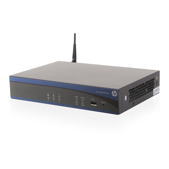
Product overview This chapter shows the chassis panels of the HP A-MSR900 Router Series models listed in Table 1. The chassis panel views shown may differ slightly from the actual panels. Table 1 The HP A-MSR900 Router Series includes the following models:... -
Page 6: A-Msr900-W Panel Views
A-MSR900-W panel views Figure 3 A-MSR900-W front panel (1) USB port (2) Reset button Figure 4 A-MSR900-W rear panel (1) Grounding screw (2) Console port (3) Ethernet WAN port ETH0 (4) Ethernet WAN port ETH1 (5) Ethernet LAN ports (ETH2 to... -
Page 7: A-Msr920 Panel Views
Figure 6 A-MSR900-W(NA) rear panel (1) Grounding screw (2) Console port (3) Ethernet WAN port ETH0 (4) Ethernet WAN port ETH1 (5) Ethernet LAN ports (ETH2 to (6) Antenna port ETH5) (7) Power adapter port A-MSR920 panel views Figure 7 A-MSR920 front panel... -
Page 8: A-Msr920-W Panel Views
A-MSR920-W panel views Figure 9 A-MSR920-W front panel (1) USB port (2) Reset button Figure 10 A-MSR920-W rear panel (1) Grounding screw (2) Antenna port (3) Console port (4) Ethernet WAN port ETH0 (5) Ethernet WAN port ETH1 (6) Ethernet LAN ports (ETH2 to ETH5) (7) Ethernet LAN ports (ETH6 to (8) Antenna port... - Page 9 Figure 12 A-MSR920-W(NA) rear panel (1) Grounding screw (2) Antenna port (3) Console port (4) Ethernet WAN port ETH0 (5) Ethernet WAN port ETH1 (6) Ethernet LAN ports (ETH2 to ETH5) (7) Ethernet LAN ports (ETH6 to (8) Antenna port (9) Power adapter port ETH9)
-
Page 10: Preparing For Installation
Preparing for installation Safety recommendations WARNING! Compliance and Safety Before installation and operation, read all of the safety instructions in the Guide supplied with your router. General safety recommendations follow: Turn off all power and remove all power cables before opening the chassis. •... -
Page 11: Emi
Table 4 Harmful gas concentration limits Max. (mg/m 0.006 0.05 0.01 To prevent overheating: Provide adequate clearance for air flow, including at least 10 cm [3.94 in] ventilation space around • the router's air intake and outlet vents. Make sure the site has an adequate cooling system. •... -
Page 12: Pre-Installation Checklist
User-supplied tools and equipment Phillips screwdriver P1 – 100 mm, P2 – 150 mm and P3 – 250 mm • Plain screwdriver P4 – 75 mm • Screws with various specifications • Meters and equipment such as HUB, terminal, and multimeter •... - Page 13 Item Requirements Yes No • The grounding cable of the chassis is grounded properly. • The grounding terminal of the AC power receptacle is grounded properly. Lightning protection • A port lightning arrester is installed. (Optional) • A power lightning arrester is installed. (Optional) •...
-
Page 14: Installing The Router
Installing the router WARNING! To avoid injury, do not touch bare wires, terminals, or parts with high-voltage hazard signs. This chapter provides instructions for installing the router on a workbench or mounting it in a 19-inch rack. Installation prerequisites You have read "Preparing for installation"... -
Page 15: Installing The Router
Figure 13 A-MSR900 router installation flowchart Start Install the router to a Install the router to a wall workbench Install the router to a specified position? Check the workbench Install wall-mounting screws Ground the router Install antennas Connect interface cables... -
Page 16: Installing The Router On A Workbench
Installing the router on a workbench To install the router on a workbench, as shown in Figure Make sure the workbench is clean, stable, and properly grounded. Place the router upside down on the workbench and attach the rubber feet to the four round holes in the chassis bottom. -
Page 17: Grounding The Router
Figure 15 Wall-mounting the router ≥ 22 mm 180 mm ≥ 1.5 mm Grounding the router WARNING! Connecting the router grounding cable correctly is crucial for protecting the router from lightning and EMI. The grounding resistance should be less than 5 ohms. You can ground the router in one of the following ways, depending on the grounding conditions at the installation site:... - Page 18 Ground the router to a properly-grounded grounding strip. • Ground the router to a grounding conductor buried in the earth. • Grounding the router with a grounding strip To connect the grounding cable: Remove the grounding screw from the rear panel of the router chassis. Put the OT terminal of the supplied grounding cable on the grounding screw, as shown in Figure Use a screwdriver to fasten the grounding screw, with the grounding cable OT terminal attached,...
-
Page 19: Installing An Antenna
Grounding the router to a buried grounding conductor If the installation site has no grounding strips but offers the option of grounding to earth, hammer a 0.5 m (1.64 ft) or longer angle iron or steel tube into the earth to serve as a grounding conductor, as shown Figure 18. -
Page 20: Connecting Interface Cables
Connecting interface cables Before powering on the router, connect the router's interface cables. Connecting an Ethernet cable The router includes WAN and LAN Ethernet ports. For a 10/100 Mbps copper Ethernet port that supports MDI/MDIX autosensing, you can use either a straight-through cable or a crossover cable to connect the port to a hub or LAN switch. -
Page 21: Connecting The Console Cable And Setting Terminal Parameters
Interface numbering The router's fixed Ethernet ports are numbered as follows: The two fixed WAN ports are numbered Ethernet 0/0 and Ethernet 0/1. • The four fixed Ethernet LAN ports are numbered Ethernet 0/1, Ethernet 0/2, Ethernet 0/3, and • Ethernet 0/4. -
Page 22: Setting Console Terminal Parameters
Setting console terminal parameters To set console terminal parameters: Select Start > All Programs > Accessories > Communications > HyperTerminal. In the Connection Description dialog box (Figure 23), enter the name of the new connection in the Name field and then click OK. Figure 23 The Connection Description interface of HyperTerminal In the Connect To dialog box (Figure... - Page 23 In the Properties dialog box (Figure 25), set Bits per second to 9600, Data bits to 8, Parity to None, Stop bits to 1, and Flow control to None, and click OK. NOTE: To restore the default settings, click Restore Defaults. Figure 25 Setting serial port parameters In the HyperTerminal window (Figure...
- Page 24 Figure 26 HyperTerminal window In the Test Properties dialog box (Figure 27), click the Settings tab, set the emulation to VT100 or Auto Detect, and click OK. Figure 27 Set the terminal emulation parameters...
-
Page 25: Connecting The Power Adapter
Connecting the power adapter The router's power adapter converts AC power to DC power, as follows: AC rated voltage range: 100 VAC to 240 VAC, 50 Hz to 60 Hz • DC Rated voltage: 12 VDC • To connect the power adapter, as shown in Figure Make sure the router is properly grounded. -
Page 26: Startup Process
Booting Normal Extend BootWare..The Extend BootWare is self-decompressing..... Done! **************************************************************************** HP A-MSR900 BootWare, Version 2.24 **************************************************************************** Copyright (c) 2010-2011 Hewlett-Packard Development Company, L.P. Compiled Date : Feb 16 2011 CPU Type : MPC8323E CPU L1 Cache : 16KB CPU Clock Speed... -
Page 27: Power-On Check
System application is starting... User interface con0 is available. Press ENTER to get started. Press Enter and the system displays the following prompt: <HP> This prompt indicates that the router has entered user view and is ready to configure. Power-on check After powering on the router, check the following items: The LEDs on the front panel are normal, as described in Table... -
Page 28: Troubleshooting
Troubleshooting This appendix provides information for troubleshooting the router. NOTE: • The barcode on the router chassis contains product information that must be provided to HP Support before returning a faulty router for service. • The HP tamper-proof label attached to a mounting screw on the router chassis must be kept intact. Before opening the chassis cover, contact HP Support for authorization;... -
Page 29: Garbled Terminal Display
Garbled terminal display If terminal display is garbled, make sure that the Data bits field for the console terminal is set to 8. If the Data bits field is set to 5 or 6, the console terminal will display garbled characters. No response from the serial port If the serial port does not respond, verify that the serial cable is in good condition and the serial port settings are correct. -
Page 30: Super Password Loss
Super password loss The super password provides access to four super levels, enabling you to perform higher-level operations. To recover from super password loss: On the main BootWare menu, select 8. This setting (Clear Super Password) is valid only for the first reboot of the router. The super password is restored after the second reboot. -
Page 31: Support And Other Resources
Support and other resources Contacting HP For worldwide technical support information, see the HP support website: http://www.hp.com/support Before contacting HP, collect the following information: Product model names and numbers • Technical support registration number (if applicable) • Product serial numbers •... -
Page 32: Conventions
Conventions This section describes the conventions used in this documentation set. Command conventions Convention Description Boldface Bold text represents commands and keywords that you enter literally as shown. Italic Italic text represents arguments that you replace with actual values. Square brackets enclose syntax choices (keywords or arguments) that are optional. Braces enclose a set of required syntax choices separated by vertical bars, from which { x | y | ... - Page 33 Network topology icons Represents a generic network device, such as a router, switch, or firewall. Represents a routing-capable device, such as a router or Layer 3 switch. Represents a generic switch, such as a Layer 2 or Layer 3 switch, or a router that supports Layer 2 forwarding and other Layer 2 features.
-
Page 34: Appendix A Technical Specifications
Appendix A Technical specifications This appendix lists the router's technical specifications. A-MSR900 specifications Table 7 A-MSR900 specifications Item 900-W 900-W(NA) 920-W 920-W(NA) NOTE: • On a device whose PCB version is earlier than 3.0, the console port cannot function as Console port an AUX port. -
Page 35: Antenna Specifications
NOTE: A-MSR900-W(NA) and A-MSR920-W(NA) are North American models. Antenna specifications Table 8 Antenna specification Item Specification Frequency range 2400 MHz to 2500 MHz Voltage Standing Wave Ratio ≤2.0 (VSWR) Input impedance 50 ohms Gain 2±1 dBi Max power consumption 25 W... -
Page 36: Appendix B Leds
Appendix B LEDs A-MSR900/A-MSR900-W/A-MSR900-W(NA) Table 9 A-MSR900/A-MSR900-W/A-MSR900-W(NA) LED description Location Status Description Steady green The power supply is connected. Front panel The power supply is not connected. Fast flashing The system is starting up. green Slow flashing The system is operating properly. -
Page 37: A-Msr920/A-Msr920-W/A-Msr920-W(Na)
A-MSR920/A-MSR920-W/A-MSR920-W(NA) Table 10 A-MSR920/A-MSR920-W/A-MSR920-W(NA) LED description Location Status Description Steady green The power supply is connected. Front panel The power supply is not connected. Fast flashing The system is starting up. green Slow flashing The system is operating properly. green Front panel Fast flashing A system problem has occurred. -
Page 38: Index
Index AC power adapter, 21 chassis adapter A-MSR900 panel views, 1 AC power, 21 A-MSR900-W panel views, 2 DC power, 21 A-MSR900-W(NA) panel views, 2 A-MSR900 A-MSR920 panel views, 3 chassis panel views, 1 A-MSR920-W panel views, 4 technical specifications, 30... - Page 39 (troubleshooting), 25 numbering, 17 grounding troubleshooting module failure, 26 buried grounding conductor, 15 grounding strip, 14 A-MSR900 technical specifications, 32 router, 13 A-MSR900-W technical specifications, 32 hardware A-MSR900-W(NA) technical specifications, 32 grounding router with buried grounding conductor,...
- Page 40 16 technical specifications installing router on wall, 12 A-MSR900, 30 installing router on workbench, 12 A-MSR900 LED, 32 installing the router, 10, 1 1 A-MSR900-W, 30 powering on the router, 22 A-MSR900-W LED, 32 setting console terminal parameters, 18...
- Page 41 A-MSR920-W(NA) LED, 33 no response from serial port, 25 antenna, 31 no terminal display, 24 LED, 32 password loss, 25 terminal power LED off, 24 setting console parameters, 18 power supply failure, 24 router installation, 24 system configuration problems, 24 troubleshooting garbled display, 25 super password loss, 26 troubleshooting no display, 24...