Table of Contents
Advertisement
Quick Links
HP A-MSR20 Router Series
Installation Guide
Abstract
This document guides you through installation of HP A Series products, including installing the device,
connecting to the network, hardware management, and troubleshooting.
Part number: 5998-1411
Software version: CMW520-R2207P02
Document version: 6PW100-20110810
Advertisement
Table of Contents

Related Manuals for HP A-MSR20


Summary of Contents for HP A-MSR20
-
Page 1: Installation Guide
HP A-MSR20 Router Series Installation Guide Abstract This document guides you through installation of HP A Series products, including installing the device, connecting to the network, hardware management, and troubleshooting. Part number: 5998-1411 Software version: CMW520-R2207P02 Document version: 6PW100-20110810... - Page 2 The only warranties for HP products and services are set forth in the express warranty statements accompanying such products and services. Nothing herein should be construed as constituting an...
-
Page 3: Table Of Contents
Contents Product overview ······························································································································································ 1 A-MSR20-20 panel views ················································································································································ 1 A-MSR20-21 panel views ················································································································································ 2 A-MSR20-40 panel views ················································································································································ 2 Preparing for installation ················································································································································· 4 Safety recommendations ·················································································································································· 4 Installation site requirements ··································································································································· 4 Cooling ······································································································································································ 5 Lightning protection ·················································································································································· 5 Rack-mounting requirements····································································································································... - Page 4 Websites ································································································································································ 38 Conventions ···································································································································································· 39 Appendix A Technical specifications··························································································································· 41 Appendix B LEDs ···························································································································································· 42 A-MSR20-20 LEDs ·························································································································································· 42 A-MSR20-21LEDs ··························································································································································· 43 A-MSR20-40 LEDs ·························································································································································· 44 Appendix C Slot arrangement and interface numbering ·························································································· 46 Slot arrangement ···························································································································································· 46 Interface numbering ·······················································································································································...
-
Page 5: Product Overview
Product overview This chapter discusses the chassis panels of the HP A-MSR20 Router Series models listed in Table 1. The chassis panel views shown may differ slightly from the actual panels. Table 1 HP A-MSR20 Router Series models Type JF283A... -
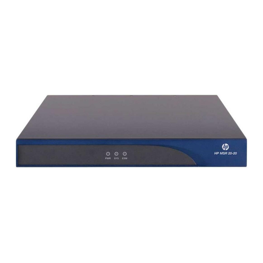
Page 6: A-Msr20-21 Panel Views
A-MSR20-21 panel views Figure 3 A-MSR20-21 front panel 1 2 3 (1) PWR LED (2) SYS LED (3) ESM LED Figure 4 A-MSR20-21 rear panel (1) SIC slot 2 (2) SIC slot 1 (3) CF card slot (4) USB port... - Page 7 Figure 6 A-MSR20-40 rear panel (1) SIC slot 4 (2) SIC slot 3 (3) Ethernet WAN ports (ETH0 and ETH1) (4) SIC slot 1 (5) SIC slot 2 (6) Grounding screw...
-
Page 8: Preparing For Installation
Preparing for installation This chapter discusses safety, site, and rack-mounting requirements, as well as the tools and accessories needed for installation. Safety recommendations WARNING! Compliance and Safety Before installation and operation, read all of the safety instructions in the Guide supplied with your router. -
Page 9: Cooling
Harmful gas concentration limits in the equipment room Maximum concentration (mg/m 0.06 0.05 0.01 Cooling Air flows through the A-MSR20 from left to right, as shown in Figure Figure 7 A-MSR20 ventilation To prevent overheating: Provide adequate clearance for air flow. ... -
Page 10: Rack-Mounting Requirements
Size. The rack must be appropriately sized to hold the switch. Ventilation. HP recommends that you mount a switch in an open rack. If you mount a switch in a closed rack, provide an adequate heat dissipation system. With either type of rack, there must be enough space around the switch's left and right panels for unimpeded airflow and heat dissipation. -
Page 11: Pre-Installation Checklist
Pre-installation checklist Table 5 Pre-installation checklist Item Requirements Yes No There is a minimum clearance of 10 cm (3.9 in) around Installation the router chassis intake and exhaust vents for heat site Ventilation dissipation. The installation site ventilation system is adequate. Temperature 0°C to 40°C (32°F to 104°F) Relative humidity... - Page 12 Item Requirements Yes No Install the router in an open rack if possible. If you install the router in a closed cabinet, make sure that the cabinet is equipped with a good ventilation system. The rack is sturdy enough to support the weight of the Rack mounting router and accessories.
-
Page 13: Installing The Router
The HP tamper-proof label attached to a mounting screw on the router chassis must be kept intact. Before opening the chassis cover, contact HP Support for authorization; if you do not, you take full responsibility for all operation and maintenance failures. -
Page 14: Installation Flowchart
Install the router on a workbench. Install the router in a 19-inch rack. Figure 8 A-MSR20 router installation flowchart Start Install the router to a rack Install the router to a specified position? -
Page 15: Installing The Router
Mounting brackets can support only the weight of the router. To avoid damaging the router, do not place any objects on it. Figure 9 Rack-mounting the A-MSR20-20/A-MSR20-21 router To mount the router in a 19-inch rack, as shown in Figure Determine where to attach the cage nuts to match the mounting bracket holes. - Page 16 Mounting brackets can support only the weight of the router. To avoid damaging the router, do not place any objects on it. Figure 11 Rack-mounting the A-MSR20-40 router To install the router in a 19-inch rack, as shown in Figure 1...
-
Page 17: Grounding The Router
Secure the router fastening the front mounting brackets to the rack with rustproof panhead screws that meet installation requirements. Figure 12 A-MSR20-40 front and rear mounting brackets (1) Left front mounting bracket (2) Right front mounting bracket (3) Left rear mounting bracket... - Page 18 Figure 13 Connecting the grounding cable to the router chassis (1) OT terminal Attach the other end of the grounding cable to the grounding strip, as shown in Figure Figure 14 Connecting the grounding cable to a grounding strip (1) Hex nut (2) Grounding cable (3) Bare metal part (4) Grounding post...
-
Page 19: Installing Interface Modules
The router provides SIC slots. On some models, you can remove a slot divider to combine two side-by- side SIC slots into one DSIC slot, as shown in Table Table 6 A-MSR20 SIC and DSIC slots Model Slot arrangement SIC 2... - Page 20 Installing a SIC interface module Figure 16 Installing a SIC interface module To install a SIC interface module, as shown in Figure Power off the router and remove the power cord. Using a Phillips screwdriver, remove the screws on the filler panel, and then remove the filler panel. Push the SIC interface module into the SIC slot along the slide rails until it is firmly seated.
-
Page 21: Connecting Interface And Power Cables
Connecting interface and power cables Before powering on the router, connect the router's interface and power cables. Connecting an Ethernet cable Figure 18 Connecting the Ethernet cable Connect one end of the Ethernet cable to an Ethernet port on the router, as shown in Figure 18, and connect the other end to the peer device. - Page 22 Select a console terminal, which can be an ASCII terminal with an RS-232 serial port or a PC. (A PC is more commonly used.) Connect the DB-9 connector (female) of the console cable to the RS-232 serial port of the console terminal, and connect the RJ-45 connector to the console port of the router.
- Page 23 Figure 21 Selecting a serial port for the HyperTerminal connection In the Properties dialog box (Figure 22), set Bits per second to 9600, Data bits to 8, Parity to None, Stop bits to 1, and Flow control to None, and then click OK. NOTE: To restore the default settings, click Restore Defaults.
- Page 24 In the HyperTerminal window (Figure 23), select File > Properties. Figure 23 HyperTerminal window In the Test Properties dialog box (Figure 24, click the Settings tab, set the emulation to VT100 or Auto Detect, and then click OK. Figure 24 Setting the terminal emulation parameters...
-
Page 25: Connecting The Ac Power Cord
Connecting the AC power cord To connect the AC power cord, as shown in Figure Make sure the router is grounded properly and the power switch of the router is in the OFF position. Connect one end of the power cord shipped with the router to the power socket on the rear panel, and connect the other end to an AC power source. - Page 26 System is starting... Do you want to check SDRAM? [Y/N] Booting Normal Extend BootWare..The Extend BootWare is self-decompressing..... Done! **************************************************************************** HP A-MSR20-21 BootWare, Version 3.13 **************************************************************************** Copyright (c) 2010-2011 Hewlett-Packard Development Company, L.P. Compiled Date : Jan 19 2011...
-
Page 27: Configuring Basic Settings For The Router
Configuring basic settings for the router After powering on the router for the first time, configure basic settings for the router. For more information, see the HP A-MSR Router Series Fundamentals Configuration Guide and the HP A-MSR Router Series Fundamentals Command Reference. -
Page 28: Installing And Upgrading Internal Modules And Frus
Opening and removing the chassis cover CAUTION: The HP tamper-proof label attached to a mounting screw on the router chassis must be kept intact. Before opening the chassis cover, contact HP Support for authorization; if you do not, you take full responsibility for all operation and maintenance failures. - Page 29 Figure 26 Removing the A-MSR20-20/20-21 chassis cover...
-
Page 30: Locating Internal Modules
Figure 27 Removing the A-MSR20-40 chassis cover Locating internal modules Internal modules are located in different places in the A-MSR20-20/20-21 and the A-MSR20-40, as shown in the following figures:... - Page 31 A-MSR20-20/20-21 Figure 28 Internal architecture of the A-MSR20-20/20-21 (1) Power supply (2) Fan (3) Front panel (4) ESM module slot (5) Rear panel...
- Page 32 A-MSR20-40 Figure 29 Internal architecture of the A-MSR20-40 (1) VCPM module slot (2) VPM module slot (3) Fan (4) Front panel (5) Power supply (6) CF card (7) ESM module slot 0 (8) ESM module slot 1 (9) Rear panel...
-
Page 33: Installing And Removing A Vpm Module
Installing and removing a VPM module The VPM module performs voice traffic compression/decompression, EC, and CNG. The following VPM module types are available: 8-channel VPM (RT-VPM8) 16-channel VPM (RT-VPM16) 24-channel VPM (RT-VPM24) 32-channel VPM (RT-VPM32) Figure 30 VPM module Installing a VPM module Figure 31 Installing a VPM module To install a VPM module, as shown in... -
Page 34: Removing A Vpm Module
Removing a VPM module To remove a VPM module, as shown in Figure Press down and pull the release latches away from the VPM module at both ends. Remove the VPM module and place it in an antistatic container. Figure 32 Removing a VPM module Installing and removing a VCPM or ESM module The VCPM module works with the VPM module and VE1/VT1 interface module to process voice traffic. -
Page 35: Installing A Vcpm Or Esm Module
Installing a VCPM or ESM module Figure 33 Installing a VCPM or ESM module To install a VCPM or ESM module, as shown in Figure Install the standoffs on the router's motherboard in the specified positions, rotating the standoffs to fasten them. -
Page 36: Removing A Vcpm Or Esm Module
Removing a VCPM or ESM module Figure 34 Removing a VCPM or ESM module To remove a VCPM or ESM module, as shown in Figure Remove all screws from the module. Unplug the module and place it in an antistatic bag. Installing and removing a CF card Installing a CF card Figure 35 Installing a CF card... -
Page 37: Removing A Cf Card
Removing a CF card Caution: Before removing a CF card, make sure that the CF card LED is not flashing. Figure 36 Removing a CF card To remove a CF card, as shown in Figure Press the ejector button once so that the eject button projects from the panel. Press the ejector button again to eject the CF card part way out of the slot. -
Page 38: Troubleshooting
The HP tamper-proof label attached to a mounting screw on the router chassis must be kept intact. Before opening the chassis cover, contact HP Support for authorization; if you do not, you take full responsibility for all operation and maintenance failures. -
Page 39: No Terminal Display
Booting Normal Extend BootWare..After the system reboots, set a new password in system view. The console port uses password authentication, and the password is set to 123456 and stored in plain text. <HP> system-view [HP] user-interface console 0 [HP-ui-console0] authentication-mode password... -
Page 40: Super Password Loss
After modifying the user password, save it by executing the save command. [HP] save NOTE: HP recommends saving the new configuration as the default configuration file. Super password loss The super password provides access to four super levels, enabling you to perform higher-level operations. -
Page 41: Interface Module, Cable, And Connection Failure
Interface module, cable, and connection failure When the LEDs on an interface module panel indicate abnormal operation: Verify that the router supports the interface module. Ensure that the interface module is installed in the correct slot and is configured correctly. Verify that the interface cable is connected correctly. -
Page 42: Support And Other Resources
Related information Documents To find related documents, browse to the Manuals page of the HP Business Support Center website: http://www.hp.com/support/manuals For related documentation, navigate to the Networking section, and select a networking category. ... -
Page 43: Conventions
Conventions This section describes the conventions used in this documentation set. Command conventions Convention Description Boldface Bold text represents commands and keywords that you enter literally as shown. Italic Italic text represents arguments that you replace with actual values. Square brackets enclose syntax choices (keywords or arguments) that are optional. Braces enclose a set of required syntax choices separated by vertical bars, from which { x | y | ... - Page 44 Network topology icons Represents a generic network device, such as a router, switch, or firewall. Represents a routing-capable device, such as a router or Layer 3 switch. Represents a generic switch, such as a Layer 2 or Layer 3 switch, or a router that supports Layer 2 forwarding and other Layer 2 features.
-
Page 45: Appendix A Technical Specifications
This appendix provides technical specifications of the router. CAUTION: Do not unplug a USB device during USB data transmission; otherwise, data loss or hardware failures may occur. To ensure data transmission stability, use only USB devices certified by HP. Table 8 A-MSR20 specifications Item... -
Page 46: Appendix B Leds
Appendix B LEDs This appendix provides information on router and router module LEDs. A-MSR20-20 LEDs Table 9 A-MSR20-20 LEDs Location Status Description Steady green The power supply is connected. Front panel The power supply is not connected. Fast flashing The system is starting up. -
Page 47: A-Msr20-21Leds
Location Status Description No data is being transmitted or received on the ETH port. A-MSR20-21LEDs Table 10 A-MSR20-21 LEDs Location Status Description Steady green The power supply is connected. Front panel The power supply is not connected. Fast flashing The system is starting up. -
Page 48: A-Msr20-40 Leds
Location Status Description No data is being transmitted or received on the ETH port. A-MSR20-40 LEDs Table 11 A-MSR20-40 LEDs Location Status Description Steady green The power supply is connected. Front panel The power supply is not connected. Fast flashing The system is starting up. - Page 49 Location Status Description Slow flashing The system is starting up. green Steady green The VCPM module is operating properly. VCPM Rear panel Steady yellow A problem has occurred with the VCPM module. No VCPM module is installed. An ETH link is present. LINK Rear panel No ETH link is present.
-
Page 50: Appendix C Slot Arrangement And Interface Numbering
—SIC slot —DSIC slot Interface numbering All fixed ports on the A-MSR20 belong to slot 0. The router interfaces are numbered in the form of interface-type X/Y, where: interface-type is the type of interface, such as serial, asynchronous, or Ethernet. - Page 51 For example, on the A-MSR20-21: The two fixed WAN ports are numbered Ethernet 0/0 and Ethernet 0/1. The eight fixed Ethernet LAN ports are numbered Ethernet 0/2, Ethernet 0/3, Ethernet 0/4, Ethernet 0/5, Ethernet 0/6, Ethernet 0/7, Ethernet 0/8, and Ethernet 0/9.
-
Page 52: Index
37 mounting router in 19-inch rack, 1 1 console cable, 17 opening and removing the chassis cover, 24 contacting HP, 38 panel views, 1 cooling (A-MSR20), 5 technical specifications, 41 device A-MSR20-21 connecting interface cable, 17 LEDs, 43... - Page 53 SIC interface module, 16 installing VPM module, 29 lightning protection, 5 interface module failure, 37 mounting A-MSR20-20 router in 19-inch rack, 1 1 locating internal modules, 26 mounting A-MSR20-21 router in 19-inch rack, 1 1 removing ESM module, 30...
- Page 54 VPM module, 29 safety (installation recommendations), 4 locating internal modules, 26 setting terminal parameters, 17 mounting A-MSR20-20 router in 19-inch rack, 1 1 SIC interface module, 16 mounting A-MSR20-21 router in 19-inch rack, 1 1 site requirements, 4 mounting A-MSR20-40 router in 19-inch rack, 12...
- Page 55 VCPM installing module, 30 installing module, 29 removing module, 30 removing module, 29 verifying installation, 21 websites, 38...