Table of Contents
Advertisement
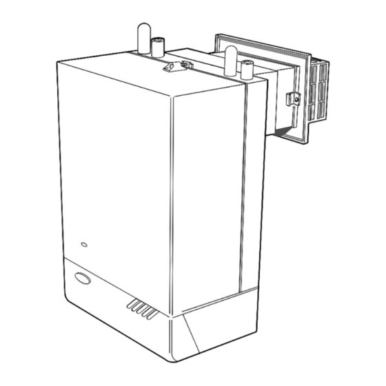
IDEAL CLASSIC
RS30, RS40, RS50 & RS60
Wall Mounted, Balanced Flue
Gas Boilers
Installation & Servicing
CAUTION: To avoid the possibility of injury during the
installation, servicing or cleaning of this appliance, care should
be taken when handling edges of sheet steel components.
IMPORTANT:
This appliance is for use with
NATURAL GAS ONLY.
NOTE TO THE INSTALLER: LEAVE THESE INSTRUCTIONS ADJACENT TO THE GAS METER
Ideal Classic
G.C. Appliance No.
RS 30
RS 40
RS 50
RS 60
41 429 35
41 429 36
41 429 37
41 429 38
Advertisement
Table of Contents

Related Manuals for IDEAL RS30l RS40


Summary of Contents for IDEAL RS30l RS40
- Page 1 IDEAL CLASSIC RS30, RS40, RS50 & RS60 Wall Mounted, Balanced Flue Gas Boilers Installation & Servicing CAUTION: To avoid the possibility of injury during the Ideal Classic G.C. Appliance No. installation, servicing or cleaning of this appliance, care should RS 30 41 429 35 be taken when handling edges of sheet steel components.
-
Page 2: Performance Data
GENERAL PERFORMANCE DATA Table 1- GENERAL DATA Boiler Size RS 30 RS 40 RS 50 RS 60 Main burner bar Aeromatic Aeromatic Aeromatic AC 19/123 263 AC 19/123 262 AC 19/123 261 Gas control HONEYWELL V 4700E 1072, 240V. Burner Injector BRAY Cat 10 Cat 10... - Page 3 GENERAL INTRODUCTION - GAS SUPPLY IMPORTANT. These appliances are certificated by the British INTRODUCTION Standards Institution for safety and performance. It is, therefore, important that no external control devices, e.g. flue The Ideal Classic RS 30, RS 40, RS 50 and RS 60 are wall dampers, economisers etc., are directly connected to these mounted, balanced flue, natural draught gas boilers.
- Page 4 GENERAL FLUE INSTALLATION - AIR SUPPLY An existing meter should be checked, preferably by the gas areas of the permanent air vents required in the cupboard/ region, to ensure that the meter is adequate to deal with the compartment are specified as follows and are related to rate of gas supply required.
-
Page 5: Installation
GENERAL AIR SUPPLY- ELECTRICAL SUPPLY Table 6 - RS 50 AIR SUPPLY The boiler is fitted with a special drain plug which is provided Position of air vent Air from room/ Air direct to drain the BOILER ONLY in the event of the system drain internal space from outside plug being unable to do so. -
Page 6: Boiler Assembly
INSTALLATION UNPACKING - BOILER ASSEMBLY 1 A UNPACKING - continued 1. Unpack the boiler 2. Remove the casing as follows, and place to one side to avoid damage. (a) Release the controls pod fixing screws (a) 3 full turns only. Remove the pod by pulling it forward to disengage from Metal clip the keyhole slots. -
Page 7: System Design
INSTALLATION SYSTEM DESIGN 3 BOILER WATER CONNECTIONS. Open vented systems. 1. This appliance is NOT suitable for use in a direct hot water system 2. If the boiler is to be used on a sealed system an overheat thermostat kit is available and must be installed, in accordance with the instructions supplied with the kit. - Page 8 INSTALLATION SYSTEM DESIGN - BOILER DIMENSIONS & CLEARANCES 5 REQUIREMENTS FOR CORRECT GRAVITY HOT WATER PERFORMANCE NOTE: Gravity horizontal pipes should be ABOVE ceiling level and as SHORT as possible. A MINIMUM inclination of 25 mm per 3 m run (1 in per 10 ft.) is required to avoid air locks. If these conditions cannot be met, pumped primaries MUST be used.
-
Page 9: Preparing The Wall
PREPARING THE WALL - MOUNTING THE BOILER INSTALLATION 10 PREPARING THE BOILER 9 PREPARING THE WALL NOTE: THE WALL MUST BE OF SUITABLE LOAD BEARING Carefully place the boiler on its side and stick the self CAPACITY. adhesive sealing tape to the boiler back panel as shown 1. - Page 10 FITTING THE FLUE ASSEMBLY - EXTENSION DUCTS INSTALLATlON 12 FITTING THE FLUE ASSEMBLY. Duct lengths up to 400 mm (16 in.) FLUE TERMINAL ASSEMBLY LEGEND A. Air duct join 1. Boiler air duct B. Flue duct join 2. Boiler flue duct 3.
-
Page 11: Electrical Connections
INSTALLATION SERVICE CONNECTIONS - WIRING DIAGRAMS 15 ELECTRICAL CONNECTIONS 14 GAS CONNECTION WARNING: The EARTH A MINIMUM gas pressure of 20 mbar (8 in.w.g.) MUST be (Green/yellow) appliance MUST be available at the boiler inlet. efficiently earthed. NEUTRAL The main gas cock is on the left hand side of the gas control (Blue) valve, as shown. -
Page 12: System Wiring Diagrams
INSTALLATION SYSTEM WIRING DIAGRAMS 19 TWO SPRING CLOSED VALVES 18 MID POSITION VALVE Pumped only Pumped only Notes: Notes: 1. Some earth wires are omitted for clarity. 1. Some earth wires are omitted for clarity. Ensure proper earth Ensure proper earth continuity when wiring. continuity when wiring. -
Page 13: Commissioning And Testing
COMMISSIONING AND TESTING INSTALLATION (b) Gas Installation 22 COMMISSIONING AND TESTING (a) Electrical Installation 1. The whole of the gas installation, including the meter, MUST be inspected and tested for soundness, and purged in accordancewith the recommendations of BS. 6891. 1. -
Page 14: General Checks
INSTALLATION COMMISSIONING AND TESTING 25 GENERAL CHECKS 5. With the system HOT, examine all water connections for Make the following checks for correct operation: soundness. Then turn OFF the gas, electricity and water supplies to the appliance and drain down whilst the system 1. - Page 15 GENERAL - CLEANING AND ADJUSTMENT SERVICING 1 SCHEDULE 2 BOILER CASING REMOVAL To ensure the continued safe and efficient operation of the 1. Refer to Frame 1. appliance, it is recommended that it is checked at regular 2. If the Ideal Classic sealed system module is fitted lift off intervals and serviced as necessary.
- Page 16 SERVICING CLEANING AND ADJUSTMENT - REPLACEMENT OF PARTS 5 CLEANING THE BURNER AND PILOT ASSEMBLY Refer to Frame 3 for illustration of the procedure below. (b) The pilot burner is clean and unobstructed. (c) The spark electrode is clean and undamaged. 1.
-
Page 17: Pilot Burner Replacement
SERVICING REPLACEMENT OF PARTS 11 PILOT BURNER REPLACEMENT 10 PIEZO UNIT REPLACEMENT 1. Refer to Frame 8. 1. Refer to Frame 8. 2. Disconnect the ignition and earth leads from 2. Remove burner and air box assembly. Refer to Frame 3. the piezo unit. -
Page 18: Replacement Of Parts
SERVICING REPLACEMENT OF PARTS 14 OVERHEAT THERMOSTAT REPLACEMENT Fitted for sealed systems only DETAIL OF 1. Refer to Frame 8. OVERHEAT 2. Slacken the screw at the thermostat pocket and withdraw THERMOSTAT POCKET the phial from pocket. 3. Unclip the capillary from back panel. 4. -
Page 19: Gas Control Valve Replacement
SERVICING REPLACEMENT OF PARTS Note: Refer also to Frame 25 'Exploded Views' for 18 GAS CONTROL VALVE REPLACEMENT illustration of the procedure detailed below. 1. Refer to Frame 8. see note 7 Manifold, see note 10 2. Remove the burner and air box assembly. Refer to Frame 3. 3. - Page 20 SERVICING REPLACEMENT OF PARTS 22 GAS VALVE SOLENOID REPLACEMENT 21 CASING SEAL REPLACEMENT 1. Refer to Frame 8. 1. Refer to Frame 8. 2. Remove the fixing screw retaining the control box cover INNER VIEW OF BOILER CASING and remove the cover. DETAIL OF CONTROL BOX Control box cover...
-
Page 21: Boiler Assembly - Exploded View
SERVICING EXPLODED VIEWS 24 BOILER ASSEMBLY - Exploded view LEGEND (Numbers up to 39 relate to the B.G. spares list) 1. Heat exchanger 8. Collector hood 26. Boiler thermostat Overheat thermostat (if 2. Flue baffles 9. Combustion chamber 28. Thermostat pocket fitted) 4. -
Page 22: Fault Finding
SERVICING FAULT FINDING Before attempting any electrical fault finding ALWAYS carry out Detailed instructions on the cleaning and adjustment or the preliminary electrical system checks as detailed in the placement of faulty components are contained in the 'Servicing' Instructions for the British Gas Multimeter, or similar test section, of this publication. -
Page 23: Short List Of Parts
SERVICING SHORT LIST OF PARTS Ideal Classic RS 30, RS 40, RS 50 and RS 60 Gas boilers The following list comprises parts commonly required as replacement components due to damage, expendability, or such that their failure or absence is likely to affect safety or When ordering spares please quote:- performance. - Page 24 SERVICING SHORT LIST OF PARTS - COMPONENT DIAGRAMS 29 SHORT PARTS 30 BOILER CASING ASSEMBLY CARADON IDEAL Ltd. pursues a policy of continuing improvement in the design and performance of its products. THIS SYMBOL IS YOUR The right is therefore reserved to vary specification without ASSURANCE OF QUALITY notice.