Invacare CROSSFIRE T6 Owners Operating & Maintenance Manual
Invacare wheelchair user manual
Hide thumbs
Also See for CROSSFIRE T6:
- Specifications (2 pages) ,
- Owner's operator and maintenance manual (64 pages) ,
- User manual (88 pages)
Table of Contents
Advertisement
Quick Links
Download this manual
See also:
User Manual
Owner's Operator and Maintenance Manual
®
Crossfire
Series
™
Wheelchairs
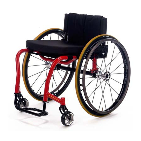
Crossfire T6
Crossfire Titanium
Crossfire All Terrain
DEALER: This manual MUST be given to
the user of the wheelchair.
USER: BEFORE using this wheelchair, read
this manual and save for future reference.
For more information regarding
Invacare products, parts, and services,
please visit www.invacare.uk
Advertisement
Table of Contents

Related Manuals for Invacare CROSSFIRE T6


Summary of Contents for Invacare CROSSFIRE T6
- Page 1 Crossfire All Terrain DEALER: This manual MUST be given to the user of the wheelchair. USER: BEFORE using this wheelchair, read this manual and save for future reference. For more information regarding Invacare products, parts, and services, please visit www.invacare.uk...
- Page 2 UNDERSTAND THE WARNINGS, CAUTIONS AND INSTRUCTIONS, CONTACT YOUR INVACARE DEALER OR INVACARE CUSTOMER SUPPORT BEFORE ATTEMPTING TO USE THIS EQUIPMENT - OTHERWISE INJURY AND/OR EQUIPMENT DAMAGE MAY OCCUR. NOTE: Updated versions of this manual are available on www.invacare.uk. Crossfire™Series Wheelchairs Part No 1148078...
-
Page 3: Table Of Contents
Tyre Pressure and Information ...13 Weight Training ...13 Weight Limitation...13 SECTION 2—SAFE HANDLING ... 14 Stability and Balance...14 Coping with Everyday Obstacles...15 A Note to Wheelchair Assistants...16 Reaching, Leaning and Bending - Forward...16 Reaching, Leaning - Backwards ...16 Tipping...17 Tipping - Curbs ...17 Stairways...18 Transferring To and From Other Seats ...19... - Page 4 TABLE OF CONTENTS Adjusting ...26 Replacing/Adjusting Optional Adjustable Angle Footrest ...26 Replacing the Footrest...26 Adjusting Footplate Angle...27 Adjusting Footplate Depth...27 SECTION 5—ARMS ... 28 Installing the Swingaway Padded Armrest Socket Assembly...28 Adjusting Swingaway Padded Armrest Height...29 SECTION 6—BACK ... 30 Unfolding/Folding the Back...30 Back Angle Adjustment ...30 Adjustable Tension Back Upholstery ...32...
- Page 5 TABLE OF CONTENTS Removing the Camber Tube ...47 Installing the Camber Tube ...47 Adjusting the Camber Tube...48 Determining Toe In/Toe Out ...49 Adjusting Fork Tension ...50 Removing/Installing/Repositioning the Caster Assemblies...51 Standard Forks...51 Removing Front Caster ...51 Installing Front Caster ...51 Suspension Forks...51 Removing the Caster ...51 Installing the Caster ...52...
-
Page 6: Special Notes
CHANGE WITHOUT NOTICE. Serial number information is located under the seat of the chair. As a manufacturer of wheelchairs, Invacare endeavors to supply a wide variety of wheelchairs to meet many needs of the end user. However, final selection of the type of wheelchair to be used by an individual rests solely with the user and his/her healthcare professional capable of making such a selection. - Page 7 Invacare products are specifically designed and manufactured for use in conjunction with Invacare accessories. Accessories designed by other manufacturers have not been tested by Invacare and are not recommended for use with Invacare products. Because TOP END wheelchairs are made to the specifications of the original own- ers it is unlikely that refurbished product would be suitable to other user’s needs.
-
Page 8: Typical Product Parameters
FIXED: BACK UPHOLSTERY: SEAT UPHOLSTERY: AXLE POSITIONS/CEN- TER OF GRAVITY: REAR WHEEL AXLE: Crossfire™Series Wheelchairs CROSSFIRE T6 CROSSFIRE TITANIUM 6061T6 Aluminum Grade 9 Titanium 70°, 75°, 80°, 85° or 90° Tubular footrest in same material as frame (Standard), Adjustable Angle NCO, Plastic or Carbon Fiber Cover (Optional) Front: 16 to 21 inches (40.64 to 53.34 cm) - Page 9 NOTE: 40.64 x 40.64 cm seat, rear wheels and minimal options are included in the weight. *NOTE: Refer to Tyre Pressure Conversion. **NOTE: 15 inch rear seat height only available with 24 inch rear wheels. Part No 1148078 CROSSFIRE T6 CROSSFIRE TITANIUM 0°, 3°, 6°, or 9°...
-
Page 10: Tyre Pressure Conversion
Tyre Pressure Conversion NOTE: PSI rating is printed on the side of the tyre. NOTE: Conversion formula: 1 psi = 6.895 kPa (appox. 7 kPa). KILOPASCALS Crossfire™Series Wheelchairs Part No 1148078... -
Page 11: Section 1-General Guidelines
Any change to one or any combination of the five may cause the wheelchair to decrease in stability. Use EXTREME caution when using a new seating position. The addition of anti-tippers may be required. -
Page 12: Operating Information
MUST be observed when traversing such surfaces. Inasmuch as the anti-tippers are an option on this wheelchair (you may order with or without the anti-tippers), Invacare strongly recommends ordering the anti-tippers as an additional safeguard for the wheelchair user. -
Page 13: Tyre Pressure And Information
Invacare DOES NOT recommend the use of its wheelchairs as a weight training apparatus. Invacare wheelchairs have not been designed or tested as a seat for any kind of weight training. If occupant uses said wheelchair as a weight training apparatus, Invacare shall not be liable for bodily injury and the warranty is void. -
Page 14: Section 2-Safe Handling
Individual wheelchair users often develop skills to deal with daily living activities that may differ from those described in this manual. Invacare recognises and encourages each individual to try what works best for him/her in overcoming architectural obstacles that they may encounter, however, ALL WARNINGS and CAUTIONS given in this manual MUST be followed. -
Page 15: Coping With Everyday Obstacles
The addition of anti-tippers may be required. NOTE: For this procedure, refer to FIGURE 2.1. Many activities require the wheelchair owner to reach, bend and transfer in and out of the wheelchair. These movements will cause a change to the normal balance, the center of gravity, and the weight distribution of the wheelchair. -
Page 16: A Note To Wheelchair Assistants
Also, be aware of any removable (detachable) parts. These must NEVER be used to move the wheelchair or as lifting supports, as they may be inadvertently released, resulting in possible injury to the user and/or assistant(s). -
Page 17: Tipping
Tipping DO NOT tip the wheelchair without assistance. DO NOT let the wheelchair drop the last few inches to the ground. This could result in injury to the occupant. When tipping the wheelchair, an assistant should grasp the back of the wheelchair on a non-removable (non-detachable) part. -
Page 18: Stairways
Extreme caution is advised when it is necessary to move an occupied wheelchair up or down a stairway. Invacare recommends that, if possible, the user be removed from the wheelchair prior to moving. Invacare recommends using two assistants and making thorough preparations. -
Page 19: Transferring To And From Other Seats
NOTE: This activity may be performed independently provided you have adequate mobility and upper body strength. Position the wheelchair as close as possible along side the seat to which you are transferring, with the front casters parallel to it. Remove the armrest, if installed. Engage wheel locks. -
Page 20: Section 3-Safety Inspection
Regular cleaning will reveal loose or worn parts and enhance the smooth operation of your wheelchair. To operate properly and safely, your wheelchair must be cared for just like any other vehicle. Routine maintenance will extend the life and efficiency of your wheelchair. Clean upholstery with mild soap and water or spray disinfectant using a sponge. -
Page 21: Inspect/Adjust Weekly
❑ Inspect spokes for bent or broken spokes. ❑ Ensure all spokes are uniformly tight. ❑ Clean upholstery and armrests. ❑ Inspect wheel/fork assembly for proper tension by spinning caster; caster should come to a gradual stop. ❑ Loosen/tighten locknut if wheel wobbles noticeably or binds to a stop. ❑... -
Page 22: Inspect/Adjust Periodically
❑ Check that all labels are present and legible. Replace if necessary. Inspect/Adjust Periodically ❑ Ensure wheelchair rolls straight (no excessive drag/pull to one side). ❑ Ensure wheel locks are easy to engage. ❑ Ensure that the casters are free of debris. -
Page 23: Maintenance
Suggested Maintenance Procedures 1. Before using your wheelchair, make sure all nuts and bolts are tight. Check all parts for damage or wear and replace. Check all parts for proper adjustment. 2. Keep quick/quad-release axles free of dirt and lint to ensure positive locking and proper operation. - Page 24 6. Regularly check for loose spokes in the rear wheels. If loose, have them adjusted. Contact a qualified technician or Invacare customer support at the telephone numbers on the back of this manual. 7. Periodically check handrims to ensure they are secured to the rear wheels. Refer to Handrim Replacement on page 41.
-
Page 25: Section 4-Footrest
Be sure the calf strap is secure when using the wheelchair. Adjusting the Footrest 1. Position new/existing footrest to desired height. 2. Tighten the allen screw of the two clamps that secure the footrest to the wheelchair frame. Part No 1148078 WARNING... -
Page 26: Installing/Adjusting Optional Clamp On Raised Footrest
3. Position the new footrest to a determined height. 4. Tighten the allen screw of the two clamps that secure the footrest to the wheelchair frame. 5. Adjust the footplate to the desired position. Refer to Adjusting Footplate Angle on page 27 and/or Adjusting Footplate Depth on page 27. -
Page 27: Adjusting Footplate Angle
3. Using the two mounting screws and locknuts, secure the footplate to the footrest tubes. NOTE: The locknuts should lie in the channel of the footplate half clamp. Mounting Clamp Positions (Allen Wheelchair Screw) Frame Clamp (Allen Screw) Footrest Tube Footplate FIGURE 4.3 Replacing/Adjusting Optional Adjustable Angle Footrest... -
Page 28: Section 5-Arms
After ANY adjustments, repair or service and BEFORE use, make sure all attaching hardware is tightened securely - otherwise injury or damage may occur. DO NOT attempt to lift or tilt a wheelchair by using any removable (detachable) parts. Lifting by means of any removable (detachable) parts of a wheelchair may result in injury to the user or damage to the wheelchair. -
Page 29: Adjusting Swingaway Padded Armrest Height
Adjusting Swingaway Padded Armrest Height NOTE: For this procedure, refer to FIGURE 5.2. 1. Remove the half arm from the arm socket. 2. Remove the mounting bolt, two washers and locknut mounted in the arm socket that determine the swingaway padded armrest height. 3. -
Page 30: Section 6-Back
Any change to one or any combination of the five may cause the wheelchair to decrease in stability. Use EXTREME caution when using a new seating position. The addition of anti-tippers may be required. - Page 31 1. Loosen, but DO NOT remove the locknuts and hex screws that secure the back angle bracket to the seat rail and the back cane. 2. Loosen the top locknut and slide the top hex screw away from the back angle bracket to adjust the cam.
-
Page 32: Adjustable Tension Back Upholstery
Any change to one or any combination of the ten may cause the wheelchair to decrease in stability. EXTREME care MUST be taken when changing the stability of the wheelchair. Refer to the chart in General Guidelines on page 11 of this manual. -
Page 33: Removing/Installing Foldover Back Upholstery
Any change to one or any combination of the ten may cause the wheelchair to decrease in stability. EXTREME care MUST be taken when changing the stability of the wheelchair. Refer to the chart in General Guidelines on page 11 of this manual. -
Page 34: Removing Foldover Back Upholstery
1. Unfasten the two fastening flaps that secure the bottom of the existing back upholstery to the back canes. 2. Unfold the top of the back upholstery. 3. Lift up on the existing back upholstery and remove from the wheelchair. Installing Foldover Back Upholstery 1. Install the new back upholstery onto the back canes. -
Page 35: Back Height Adjustment (Adjustable Backs Only)
3. Reinstall the fastening flaps onto the back canes. NOTE: The fastening flap with logo is for the left back cane. NOTE: Right and left is determined by sitting in the wheelchair. 4. Adjust the new back upholstery to the desired tautness. Refer to Back Height Adjustment (Adjustable Backs Only) on page 35. -
Page 36: Section 7-Seat
NOTE: The seat upholstery MUST be positioned with the three rear adjusting straps towards the rear of the top crossbar for proper installation. NOTE: Make sure the rear retaining flap is between the wheelchair frame and the back cane support brackets (adjustable backs only). - Page 37 SECTION 7—SEAT Fastening Flaps Seat Adjuster Anchor Loop Upholstery Straps (Rear) Wheelchair Frame (Top Bar) Top Crossbar FIGURE 7.1 Replacing Adjustable Tension Seat Upholstery Part No 1148078 Crossfire™Series Wheelchairs...
-
Page 38: Section 8-Wheels
Removing/Installing Rear Wheels Changing the size of the rear wheels can affect the performance of the wheelchair. Contact Invacare at the telephone numbers on the back of this manual before changing rear wheel size. NOTE: For this procedure, refer to FIGURE 8.1. -
Page 39: Adjusting Quick-Release Axles
38. Replacing Quad-Release Axles NOTE: For this procedure, refer to FIGURE 8.3. 1. Remove rear wheel and the existing quick-release axle from the wheelchair. Refer to Removing/Installing Rear Wheels on page 38. 2. Remove existing quick-release axle from rear wheel. -
Page 40: Adjusting Quad-Release Handles
7. Repeat the above procedures until the quad-release axle locks correctly. Removing Play from Rear Wheels 1. With the rear wheel and quad-release axle still mounted onto the wheelchair, make the following adjustment: • Tighten the length adjusting screw until there is no in and out movement of the quad-release axle and rear wheel. -
Page 41: Handrim Replacement
DO NOT inflate tyre until it is completely assembled. Otherwise injury or damage may result. 6. Inflate tyre to correct psi rating on the sidewall of tyre. 7. Reinstall rear wheel to the wheelchair. Refer to Removing/Installing Rear Wheels on page 38. 8. Repeat STEPS 1-7 for opposite rear wheel if necessary. -
Page 42: Repairing/Replacing Rear Wheel, Tyre/Tube
Removing/Installing the Elastomers (Suspension Forks Only) on page 54 ONLY after contacting Invacare. Anti-tipper height (if applicable) must also be adjusted to maintain 1-1/2 to 2-inch (3.81 to 5.08 cm) clearance between bottom of the anti-tipper wheels and the floor. Refer to Adjusting/Replacing Anti-tipper on page 58. - Page 43 Front Caster SOCKET SCREW MOUNTING POSITIONS CAMBER TUBE MOUNTING BRACKET FACING THE FRONT OF THE WHEELCHAIR NOTE: Camber tube mounting bracket shown in forward most position. Front of Wheelchair Mounting Positions Mounting Positions Mounting Positions FIGURE 8.6 Adjusting Wheelbase Length (Adjusting Center of Gravity)
-
Page 44: Repositioning The Camber Tube Mounting Brackets
Repositioning the Camber Tube Mounting Brackets NOTE: For this procedure, refer to FIGURE 8.7. 1. Remove the rear wheels. Refer to Removing/Installing Rear Wheels on page 38. 2. Loosen but do not remove the four socket screws and washers that secure the two camber tube mounting brackets to the camber tube supports. -
Page 45: Reversing The Camber Tube Mounting Bracket Direction
4. Align the desires mounting positions of the camber tube mounting brackets with the opening of the camber tube supports. 5. Install the four socket screws, washers, and lock washers into the desired mounting positions of both camber tube mounting brackets. Hand tighten. 6. -
Page 46: Adjusting Wheelbase Width
Adjusting Wheelbase Width NOTE: For this procedure, refer to FIGURE 8.10. NOTE: Perform this procedure on one side of the wheelchair at a time for ease of adjustment. NOTE: The wheelbase width can be increased/decreased by 1-inch (2.54 cm). 1. Remove the rear wheels. Refer to Removing/Installing Rear Wheels on page 38. -
Page 47: Removing/Installing/ The Camber Tube
Removing/Installing/ the Camber Tube Camber tube mounting clamps - Make sure the mounting screws are securely tightened before using the wheelchair, otherwise personal injury or damage to the wheelchair may occur. NOTE: For this procedure, refer to FIGURE 8.11. NOTE: When replacing or changing the camber tube, perform with the new camber tube. -
Page 48: Adjusting The Camber Tube
90° angle with the ground/floor. 3. Securely tighten the four socket screws camber tube clamps. 4. Determine the toe in/toe out of the wheelchair. Refer to Adjusting Wheelbase Length (Adjusting Center of Gravity) on page 42. Flat Edge of Camber Tube (Place “L”... -
Page 49: Determining Toe In/Toe Out
2. Measure the distance between the centerlines at the rear and front of the rear wheels at approximately 12 inches (30.48 cm) from the ground/floor (FIGURE 8.13). NOTE: For optimum accuracy, perform STEP 2 with the wheelchair occupied. 3. Determine difference between two measurements. If difference between the two measurements is greater than ½-inch (1.27 cm) (0 + ¼-inch (.64 cm) for maximum... -
Page 50: Adjusting Fork Tension
1. To properly tighten forks and guard against flutter, perform the following check on both forks: A. Tip back the wheelchair to floor. B. Pivot both forks and casters to top of their arc simultaneously. C. Let casters drop to bottom of arc (wheels should swing once to one-side, then immediately rest in a straight downward position). -
Page 51: Removing/Installing/Repositioning The Caster Assemblies
Removing/Installing/Repositioning the Caster Assemblies NOTE: If replacing a front caster note the mounting position of the existing front caster for installation of the new front caster. NOTE: Both front casters MUST be the same size and adjusted to the same height. Standard Forks NOTE: For this procedure, refer to FIGURE 8.15. -
Page 52: Installing The Caster
Installing the Caster 1. Align the caster with the desired mounting holes in the fork. 2. Insert the threaded bushing with mounting screw, through the two axle spacers and caster. DO NOT use excessive force. Use Loctite™242 when reinstalling the mounting screw into the threaded bushing. Otherwise the fork can become disassembled. -
Page 53: Installing Fork Assembly
Installing Fork Assembly 1. Perform one of the following: • Standard Forks - Using a locknut and washer, secure the spacer and fork to the fork stem (Detail “A”). • Suspension Fork (Detail “B”) - a. Using a locknut and washer, secure the spacer and suspension fork top to the fork stem. -
Page 54: Removing/Installing The Elastomers (Suspension Forks Only)
Removing/Installing the Elastomers (Suspension Forks Only) DO NOT use excessive force when removing/installing the threaded sleeve from/onto the fork. Damage to the threaded sleeve may occur. NOTE: For this procedure, refer to FIGURE 8.18. Removing the Elastomer NOTE: One mounting screw will not turn. 1. -
Page 55: Section 9-Wheel Locks
- otherwise injury or damage may result. Replacing/Adjusting the Wheel Locks If wheel locks do not hold the occupied wheelchair in place contact a qualified tech- nician - otherwise injury or damage may occur. NOTE: For this procedure, refer to FIGURE 9.1 on page 56. -
Page 56: Changing Wheel Lock Handle Position
Push-to-Lock or Pull-to-Lock Wheel Locks 3/16 inch (.47 cm) Mounting Screws (1/8-inch) (.32 cm) Wheel Lock Tyre FIGURE 9.1 Replacing/Adjusting the Wheel Locks Changing Wheel Lock Handle Position NOTE: For this procedure, refer to FIGURE 9.2. 1. Loosen, but DO NOT remove, the rear handle mounting screw. 2. -
Page 57: Converting Wheel Lock From Push-To-Lock To Pull-To-Lock Or Pull-To-Lock To Push-To-Lock
Converting Wheel Lock From Push-to-Lock to Pull-to-Lock or Pull-to-Lock to Push-to-Lock NOTE: For this procedure, refer to FIGURE 9.3. Converting From Push-to-Lock to Pull-to-Lock 1. Remove set screw from the lower stop position (Detail “A”). NOTE: As the wheel lock handle is pushed downwards, the wheel lock will engage and then disengage the wheel. -
Page 58: Section 10-Anti-Tipper
Anti-tippers MUST be attached at all times. Inasmuch as the anti-tippers are an option on this wheelchair (you may order it with or without the anti-tippers), Invacare strongly recommends ordering the anti-tippers as an additional safeguard for the wheelchair user. -
Page 59: Replacing Anti-Tipper
2-inch (3.81 and 5.08 cm) clearance between the bottom of the anti-tipper wheels and the ground/floor. This spacing should always be checked whenever adjust- ments/changes are made to the wheelchair. Failure to maintain proper spacing may result in the chair tipping over backward causing serious injury or property damage. -
Page 60: Limited Warranty
THIS WARRANTY IS EXTENDED ONLY TO THE ORIGINAL PURCHASER OF OUR PRODUCTS AND DOES NOT AFFECT STATUTORY RIGHTS. Invacare UK warrants the frames to be free from defects in materials and workmanship for the lifetime of the original purchaser/user. All remaining components are warranted for a period of one (1) year from the date of purchase except upholstered materials, padded materials and tires/wheels.