Table of Contents
Advertisement
Available languages
Available languages
Quick Links
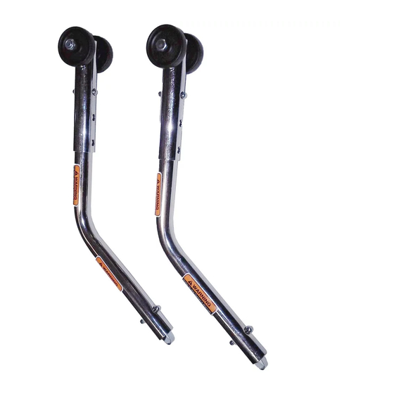
Anti-tippers
Assembly, Installation and Operating Instructions
Kit Nos. 1036900, 1036901, 1064227, 1086189, and 1086190
NOTE: Check ALL parts for shipping damage. In case of shipping damage, DO NOT use. Contact
Carrier/Dealer for further instruction.
This kit includes the following:
*NOTE: Not included with Kit Nos. 1064227, 1086189, and 1086190.
NOTE: To ensure the correct model anti‐tipper is used, refer to Rear Anti‐Tipper Application
Chart on page 4.
To ensure the safe and proper installation of the anti‐tippers, these instructions MUST be
followed:
Invacare products are specifically designed and manufactured for use in conjunction
with Invacare accessories. Accessories designed by other manufacturers have not
been tested by Invacare and are not recommended for use with Invacare products.
DO NOT install this equipment without first reading and understanding this
instruction sheet. If you are unable to understand the warnings, cautions and
instructions, contact a healthcare professional, dealer or technical personnel if
applicable, before attempting to install this equipment - otherwise, injury or
damage may occur.
Inasmuch as anti-tippers are an option on a particular wheelchair (you may order
with or without the anti-tippers), Invacare strongly recommends ordering
anti-tippers as an additional safeguard for the wheelchair user.
Anti-tippers are specific to the different rear wheels and/or seat-to-floor heights.
Refer to this instruction sheet for correct usage and adjustment. If these require-
ments CANNOT be achieved, DO NOT use the wheelchair. Contact an Invacare
dealer or qualified technician. Any changes to the seat-to-floor angle or seat-to-floor
height may require different anti-tippers. The correct anti-tippers must be ordered
to maintain a 1½ to 2-inch ground clearance.
For more information regarding Invacare products, parts, and services,
Part No 1086188
SAVE THESE INSTRUCTIONS
DESCRIPTION
Anti-Tipper
Anti-Rattle*
Safety Summary
WARNINGS
INSTALLATION WARNINGS
please visit www.invacare.com
QUANTITY
2
2
1
Anti-tippers
Advertisement
Table of Contents

Related Manuals for Invacare 1036900


Summary of Contents for Invacare 1036900
-
Page 1: Safety Summary
Invacare products are specifically designed and manufactured for use in conjunction with Invacare accessories. Accessories designed by other manufacturers have not been tested by Invacare and are not recommended for use with Invacare products. DO NOT install this equipment without first reading and understanding this instruction sheet. -
Page 2: Installing Anti-Tippers
INSTALLATION WARNINGS (CONTINUED) Anti-tippers MUST be fully engaged. Ensure that the locking pin of the anti-tipper fully protrudes out of the hole on the wheelchair frame. Ensure both anti-tippers are adjusted to the same height. Anti-tippers MUST be used at all times. When outdoors on wet, soft ground or on gravel surfaces, anti-tippers may not provide the same level of protection against tipover. -
Page 3: Adjusting Anti-Tippers
8. Measure the distance between the bottom of the anti‐tipper wheels and the ground/floor. • Non‐Adjustable Height Anti‐Tipper Assemblies: If the distance between the bottom of the anti‐tipper wheels and the ground/floor is not 1½ to 2‐inches, call Invacare Technical Support at the number listed on the back page. • Adjustable Height Anti‐Tipper Assemblies: If the distance between the bottom of anti‐tipper wheels and the ground/floor is not 1½ to 2‐inches, adjust anti‐tippers. Refer to Adjusting Anti‐Tippers on page 3. *NOTE: Non‐adjustable anti‐tipper shown. *Anti-Tipper FIGURE 1 Installing Anti-Tippers Adjusting Anti-Tippers NOTE: For this procedure, refer to FIGURE 2. NOTE: A 1½ to 2‐inch clearance between the bottom of the anti‐tipper wheels and the ground/floor MUST be maintained at all times. 1. Press the release buttons near the wheeled portion of the anti‐tipper and slide the anti‐tipper up or down to achieve the 1½ to 2‐inch clearance. 2. Check to make sure that the release buttons are fully engaged in the adjustment holes. WARNINGEnsure both anti-tippers are adjusted to the same height. FIGURE 2 Adjusting Anti-Tippers... - Page 4 After 1/99 (Including Chairs With Amputee and 1 - Arm Drive Options) All 20-inch Rear Wheel Models After Tracer EX 1/99 All Swingaway Front Frame Models Invacare MG Before 2/99 All Swingaway Front Frame Models Invacare MG After 1/99 Invacare MG All Fixed Front Models CareGuard™...
-
Page 5: Limited Warranty
If within such warranty period any such product shall be proven to be defective, such product shall be repaired or replaced, at Invacare's option. This warranty does not include any labor or shipping charges incurred in replacement part installation or repair of any such product. - Page 6 Les produits Invacare sont spécifiquement conçus et fabriqués pour être utilisés avec les accessoires Invacare. Les accessoires conçus par d’autres manufacturiers n’ont pas été testés par Invacare et leur utilisation n’est pas recommandée avec les produits Invacare. NE PAS installer cet équipement sans d’abord avoir lu et compris ce feuillet d’instructions.
- Page 7 AVERTISSEMENTS POUR L’INSTALLATION (SUITE) demander un changement du type d’antibascules. Le bon type d’antibascules doit être commandé pour maintenir un espace de 1½ à 2 pouces avec le sol. Les antibascules DOIVENT être complètement enclenchés. S’assurer que les goupilles des antibascules ressortent complètement des orifices sur le châssis du fauteuil.
- Page 8 8. Mesurer la distance entre le bas de l’antibascule et le sol\plancher. • Antibascules fixes: si la distance entre le bas des roues des antibascules et le sol\plancher n’est pas de 1½ à 2 pouces, contacter le service technique Invacare au numéro indiqué à la dernière page. • Antibascule à hauteur réglable : si la distance entre le bas des roues des antibascules et le sol\plancher n’est pas de 1½ à 2 pouces, régler les antibascules. Se référer à Régler les antibascules on page 8. *NOTE: antibascule bascule fixe. *Antibascule FIGURE 1 Installer les antibascules Régler les antibascules NOTE: Pour cette procédure, se référer à la FIGURE 2. NOTE: Un espace de 1½ à 2 pouces entre le bas des roues des antibasucles et le sol\plancher DOIT être maintenu en tout temps.. 1. Enfoncer les poussoirs de la partie portant les roues sur l’antibascule et déplacer l’antibascule vers le haut ou vers le bas afin d’obtenir un espace de 1½ à 2 pouces. 2. S’assurer que les poussoirs ressortent complètement des orifices de réglage. S’assurer que les antibascules sont réglés à la même hauteur.
- Page 9 1 - Option Arm Drive ) Tous les modèles avec roues arrières Tracer EX de 20 pouces fabriqués après 1/99 Tous les modèles avec châssis avant Invacare MG pivotant fabriqués avant 2/99 Tous les modèles avec châssis avant Invacare MG pivotant fabriqués après 1/99 Tous les modèles avant fixes...
- Page 10 SERIES COMMENTAIRES/RÉGLAGES ANTI- ANCIENNE OPTION COU- BAS- OPTION RANTE CULES (MODÈLE #/ ARRIÈRE Optionnel Tous les modèles avec One Arm 1358N/1036901 1358B Drives ou option pour amputés Antibascules Part No 1086188...
-
Page 11: Garantie Limitée
Fournir le nom du fournisseur, l’adresse, la date d’achat, la nature du défaut et le numéro de série si le produit en a un. Invacare émettra une autorisation de retour. L’unité ou les pièces défectueuses doivent être retournées pour inspection dans les trente (30) jours de la date d’autorisation de retour. - Page 12 570 Matheson Blvd E Unit 8 Elyria, Ohio USA Mississauga Ontario 44036-2125 L4Z 4G4 Canada 800-333-6900 800-668-5324 Invacare is a registered trademark of Invacare Corporation. Yes, you can. and CareGuard are trademarks of Invacare Corporation. ©2005 Invacare Corporation Part No 1086188 Rev C - 1/05...