Table of Contents
Advertisement
User Manual
EN
Invacare® MA50 Series
MA50 Alternating Pressure Overlay System
MA51 Alternating Pressure Mattress System
MA55 Alternating Pressure Low Air Loss Mattress System
This manual MUST be given to the user of the product.
BEFORE using this product, read this manual and save for future reference.
Advertisement
Table of Contents
Troubleshooting

Related Manuals for Invacare MicroAIR MA50


Summary of Contents for Invacare MicroAIR MA50
- Page 1 User Manual Invacare® MA50 Series MA50 Alternating Pressure Overlay System MA51 Alternating Pressure Mattress System MA55 Alternating Pressure Low Air Loss Mattress System This manual MUST be given to the user of the product. BEFORE using this product, read this manual and save for future reference.
- Page 2 © 2011 Invacare Corporation. All rights reserved. Republication, duplication or modification in whole or in part is prohibited without prior written permission from Invacare. Trademarks are identified by ™ and ®. All trademarks are owned by or licensed to Invacare Corporation or its subsidiaries unless otherwise noted.
-
Page 3: Table Of Contents
Transferring Patient From/To a Gurney... 26 Transferring Patient From/To a Wheelchair ... 27 Preparing for CPR Procedure ... 27 About Power Outage and Transportation... 28 MAINTENANCE AND TROUBLESHOOTING Cleaning the System ... 29 Troubleshooting... 32 Part No 1148136 CONTENTS Invacare® MA50 Series... -
Page 4: General
Caution indicates a potentially hazardous situation which, if not avoided, may result in property damage or minor injury or both. IMPORTANT Indicates a hazardous situation that could result in damage to property if it is not avoided. Gives useful tips, recommendations and information for efficient, trouble-free use. Invacare® MA50 Series Part No 1148136... -
Page 5: Limited Warranty
Invacare warrants the mattress, mattress overlay and cover when purchased new and unused to be free from defects in materials and workmanship for a period of one year from the date of purchase from Invacare or a dealer, with a copy of the seller’s invoice required for coverage under this warranty. -
Page 6: Overview
Patient entrapment with bed side rails may cause injury or death. Mattress MUST fit bed frame and side rails snugly to prevent patient entrapment. Follow the manufacturer’s instructions. Monitor patient frequently. Read and understand the Owner’s/Operator’s Manual prior to using this equipment. Invacare product manuals are available at www.invacare.com or your dealer. -
Page 7: Typical Product Parameters
Dual fused, 250 V, 1 A fast blow fuses Continuous MA50/MA51/MA55 50° - 104° F 30% - 75% Non-Condensing 70 - 106 kPa -40° - 158° F 10% - 100% Non-Condensing 50 - 106 kPa 2 OVERVIEW Invacare® MA50 Series... - Page 8 DIMENSIONS (L X W X H): WEIGHT: POWER CORD: CONNECTION: PACKAGING: AIR FILTER: Invacare® MA50 Series Control unit and mattress have Latex-Free com- MA50 MA51 9” x 5” x 5” 5 lbs 10 - 14 Feet Long, Hospital Grade Two ¼” Flow Couplings...
-
Page 9: General Guidelines
Invacare and are not recommended for use with Invacare products. NOTICE THE INFORMATION CONTAINED IN THIS DOCUMENT IS SUBJECT TO CHANGE WITHOUT NOTICE. Check all parts for shipping damage and test before using. In case of damage, DO NOT use. Contact Invacare/Carrier for further instruction. Contraindications WARNING ALWAYS consult the patient’s physician before using the MA50, MA51 and MA55 systems. - Page 10 Secure the straps to the bed deck at the head and foot ends and to the frame at the center of the bed. Otherwise damage to the mattress will occur when the head and foot ends are raised. Refer to Installing the Mattress on page 14. Invacare® MA50 Series Part No 1148136...
- Page 11 There is a possible fire hazard when used with oxygen administering equipment other than nasal mask or half bed tent type. The oxygen tent should NOT extend below mattress support level. Part No 1148136 3 GENERAL GUIDELINES Invacare® MA50 Series...
-
Page 12: Entrapment May Occur
Visit the FDA website at http://www.fda.gov to learn about the risks of entrapment. Review “A Guide to Bed Safety”, published by the Hospital Bed Safety Workgroup, located at www.invacare.com. Use the link located under each bed rail product entry to access this bed safety guide. - Page 13 The control unit MUST be kept away from all heat sources and radiators during operation. Connect the equipment to properly grounded three prong wall outlet using 10-14 ft hospital grade power cord provided with the product. Grounding reliability depends upon a properly grounded receptacle (3-prong). Part No 1148136 3 GENERAL GUIDELINES Invacare® MA50 Series...
-
Page 14: Operation
Secure the overlay mattress to the existing foam mattress using the two buckle straps. Ensure that the side rails can move freely. Invacare® MA50 Series Head End Elastic Strap Foam Mattress FIGURE 1 Installing the Mattress - Overlay System (MA50) - Page 15 • Foot End - Foot End Bed Deck • Center - Center of the Bed Frame Part No 1148136 Head End Bed Deck DO NOT Strap Here 4 OPERATION Center of Bed Frame Foot End Bed Deck Invacare® MA50 Series...
-
Page 16: Installing The Side Rails
Patient entrapment with bed side rails may cause injury or death. Mattress MUST fit bed frame and side rails snugly to prevent patient entrapment. Follow the manufacturer’s instructions. Monitor patient frequently. Read and understand the Owner’s/Operator’s Manual prior to using this equipment. Invacare product manuals are available at www.invacare.com or your dealer. -
Page 17: Installing The Power Unit
Push the hose connectors onto the control connectors until an audible click is heard. The audible click indicates that the hose connectors are properly engaged with the control connectors. Part No 1148136 Bed Hooks FIGURE 3 Installing the Power Unit 4 OPERATION Invacare® MA50 Series... - Page 18 4 OPERATION Control Unit Connectors Hose Connector Hose FIGURE 4 Connecting the Hose Invacare® MA50 Series Part No 1148136...
-
Page 19: Connecting The Power Cord
Plug the other end of the plug into a properly grounded outlet on the wall. Once the unit is plugged in, an Amber led on the control unit is lit indicating that the system is in stand by mode. Part No 1148136 4 OPERATION Invacare® MA50 Series... -
Page 20: Using The Front Panel
Static/Alternating Pressure Button DETAIL “B” - MA55 FRONT PANEL Fowler Button Soft Button Alarm Silence Button Static/Alternating Pressure Button Invacare® MA50 Series Power Button LCD Display Power Button FIGURE 5 Using the Front Panel Power Fail LED Low Pressure Max Inflate... - Page 21 50% of the selected pressure setting. Ensure the Standby LED is lit. Perform one of the following: Part No 1148136 ) to select between Static Mode and one of four Alternating Pressure Times. 4 OPERATION Invacare® MA50 Series...
- Page 22 The Fowler LED illuminates when in this mode. When this mode is activated, the control unit increases the pressure in the mattress to prevent the patient from bottoming out. Invacare® MA50 Series ) or Soft ( ) button. ) to activate the patient fowler mode.
- Page 23 It is recommended that Max Inflate setting be used during patient ingress/egress, patient wound care, patient turning or patient cleaning. Part No 1148136 ) to select the Max Inflate mode and inflate the mattress rapidly to maximum firmness (pressurized to 35 4 OPERATION Invacare® MA50 Series...
- Page 24 In the event that the mattress hose disconnects, an alarm sounds and Low Pressure LED flashes AMBER. Once the low pressure problem is fixed, the control unit resumes operation in the previously set mode. Invacare® MA50 Series ) to silence the alarm that sounds in the event of power failure or when the hose is disconnected from...
-
Page 25: Powering Up The System
Wait five minutes for the mattress pressure to stabilize. Once the mattress inflates to its normal size, set the comfort pressure to the desired comfort level. Wait five minutes for the mattress pressure to stabilize. Part No 1148136 4 OPERATION Invacare® MA50 Series... -
Page 26: Transferring Patient From/To A Gurney
When the mattress has reached maximum firmness, perform one of the following: • Bed to Gurney Transfer - Slide the patient onto the gurney. • Gurney to Bed Transfer - Slide the patient onto the bed. Invacare® MA50 Series Part No 1148136... -
Page 27: Transferring Patient From/To A Wheelchair
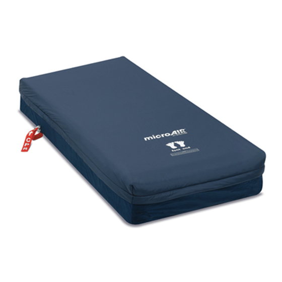
For this procedure, refer to FIGURE 6 on page 28. Press and hold the tabs on hose connector while pulling the hose from the control unit. Disconnect the RED CPR connector located on the side of the mattress. Part No 1148136 4 OPERATION Invacare® MA50 Series... -
Page 28: About Power Outage And Transportation
If the hoses remain connected to the control unit, the mattress retains air during a power outage, during transportation, when the control unit is unplugged or when the control unit is turned Off. If the hose becomes disconnected or damaged and the mattress deflates, the mattress has a 2-inch foam pad to provide patient support. Invacare® MA50 Series RED CPR Connector FIGURE 6 Preparing for CPR Procedure... -
Page 29: Maintenance And Troubleshooting
Remove all visible soil with disposable paper towels. Scrub the area with freshly prepared effective detergent disinfectant solution. • If blood is not present, remove any soil from the cover with paper towels. Part No 1148136 5 MAINTENANCE AND TROUBLESHOOTING Invacare® MA50 Series... - Page 30 DO NOT overload the machine. DO NOT use chlorine bleach because it may damage the fabric coating. High air temperatures will damage the fabrics and void the Invacare warranty. Place the cover in a washing machine. Wash with warm water (below 120°F).
- Page 31 Disconnect the air hose connector(s) from the control unit and allow air to vent from the mattress. Gently roll up the mattress with minimal handling and agitation. Ensure the cover surface is inside the roll. Store the unit, keeping the mattress with the control unit. Part No 1148136 5 MAINTENANCE AND TROUBLESHOOTING Invacare® MA50 Series...
-
Page 32: Troubleshooting
Control unit off Power cord disconnected No power in the power source Power outage Blown fuse Invacare® MA50 Series SOLUTION Connect hose connectors and lock them in place Unkink hose or replace split hose Replace leaking air cushions or overlay pad... -
Page 33: Part No 1148136 Invacare® Ma50 Series
NOTES NOTES Part No 1148136 Invacare® MA50 Series... - Page 34 NOTES NOTES Invacare® MA50 Series Part No 1148136...
- Page 35 NOTES NOTES Part No 1148136 Invacare® MA50 Series...
- Page 36 Part No 1148136 Rev C- 1/11 Invacare Corporation Canada One Invacare Way 570 Matheson Blvd E Elyria, Ohio USA Unit 8 44036-2125 Mississauga Ontario 800-333-6900 L4Z 4G4 Canada 800-668-5324 www.invacare.com...