Table of Contents
Advertisement
USER'S MANUAL
Of
Intel X58 Express Chipset
And
Intel ICH10R Chipset
Based
M/B for Intel Core i7 Processors
NO. G03-BI600 -F
Rev: 2.0
Release date: April, 2009
Trademark:
* Specifications and Information contained in this documentation are furnished for information use only, and are subject to
change at any time without notice, and should not be construed as a commitment by manufacturer.
Advertisement
Table of Contents

Related Manuals for Intel ICH10R


Summary of Contents for Intel ICH10R
- Page 1 USER'S MANUAL Intel X58 Express Chipset Intel ICH10R Chipset Based M/B for Intel Core i7 Processors NO. G03-BI600 -F Rev: 2.0 Release date: April, 2009 Trademark: * Specifications and Information contained in this documentation are furnished for information use only, and are subject to...
- Page 2 Environmental Protection Announcement Do not dispose this electronic device into the trash while discarding. To minimize pollution and ensure environment protection of mother earth, please recycle.
-
Page 3: Table Of Contents
TABLE OF CONTENT SAFETY ENVIROMENTAL INSTRUCTION ...iii USER’S NOTICE...iv MANUAL REVISION INFORMATION ...iv COOLING SOLUTIONS ...iv CHAPTER 1 INTRODUCTION OF X58 EXPRESS AND ICH10R MOTHERBOARDS FEATURES OF MOTHERBOARD ... 1 1-1.1 SPECIAL FEATURES OF MOTHERBOARD... 2 SPECIFICATION... 4 PERFORMANCE LIST... 5 LAYOUT DIAGRAM ... -
Page 4: Safety Enviromental Instruction
4-12 G.P.I.FUNCTION LED DISPLAY ... 48 Safety Environmental Instruction Avoid the dusty, humidity and temperature extremes. Do not place the product in any area where it may become wet. 0 to 40 centigrade is the suitable temperature. (The figure comes from the request of the main chipset) Generally speaking, dramatic changes in temperature may lead to contact malfunction and crackles due to constant thermal expansion and contraction from... -
Page 5: User's Notice
In addition, interface materials allow effective transfers of heat from the processor to the heat sink. For optimum heat transfer, Intel recommends the use of thermal grease and mounting clips to attach the heat sink to the processor. -
Page 6: Features Of Motherboard
24 GB capacity and the new generation of PCI Express interface for the latest graphics cards from both AMD and nVidea. The X58 Express and ICH10R chipset motherboard series are absolutely the ultimate solution for game enthusiasts and applications, and it also meets the demanding usage of computing of gaming, multimedia entertainment and business applications. -
Page 7: 1-1.1 Special Features Of Motherboard
ways. But please be caution that the over-clocking may cause the failure in system reliability. This motherboard provides the guaranteed performance and meets the demands of the next generation computing. But if you insist to gain more system performance with variety possibilities of the components you choose, please be careful and make sure to read the detailed descriptions of these value added product features, please get them in the coming section. -
Page 8: Reset Button
G.P.I. Function —(Green power indicator function) The full name of G.P.I technology is Green Power Indicator technology, obviously technology utilized to low power consumption. G.P.I is a technology with remarkable power saving function. DIY Clear The CMOS Button is to facilitate the clear COMS process for power user overclocking function. -
Page 9: Specification
∗ PCI-Express2.0 x4 slot 1pcs Expansion Slots ∗ 32-bit PCI slot x 1pcs ∗ The Intel ICH10R supports six internal Serial ATA ports for six ∗ JMB363 supports PCI Bus Mastering, ATA PIO/DMA and the Integrate IDE and Serial ATA2 RAID ∗... -
Page 10: Performance List
Performance List The following performance data list is the testing result of some popular benchmark testing programs. These data are just referred by users, and there is no responsibility for different testing data values gotten by users (the different Hardware & Software configuration will result in different benchmark testing results.) Test Configuration: CPU:... -
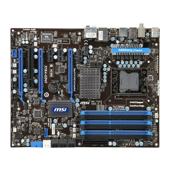
Page 11: Layout Diagram
RJ-45 Ports ESATA Connectors USB connectors ATX 12V Power Conn. LGA 1366 CPU Socket USB Power On Jumper (JP3) CPU FAN Intel X58 Express Chipset 8Mbit SPI Flash ROM BIOS Clear CMOS (JBAT) Serial Port Header Floppy Connector ATA 133 IDE... - Page 12 Jumpers Jumper JBAT CMOS RAM Clear Keyboard Power On Enabled/Disabled JP3/JP4 USB Power On Enabled/Disabled Connectors Connector ATXPWR1 ATX12V1 USB from CN1,CN2 and UL1, UL2 RJ45 LAN from UL1,UL2 AUDIO1 FLOPPY1 IDE1 DSATA1,DSATA2, DSATA3 E-SATA from CN1,CN2 SPDIF_ Out1 Headers Header FP_AUDIO1 SPEAKER, MIC header...
-
Page 13: Chapter 2 Hardware Installation
Hardware Installation WARNING! Turn off your power when adding or removing expansion cards or other system components. Failure to do so may cause severe damage to both your motherboard and expansion cards. Hardware installation Steps Before using your computer, you had better complete the following steps: 1. -
Page 14: Glossary
(2) Keyboard function Enabled/Disabled: JP1 2-3 Closed KB Power ON Enabled 1-2 Closed KB Power ON Disable (Default) Keyboard/Mouse Power On Setting (3) USB Power On function Enabled/Disabled: JP3/JP4 JP3 / JP4 JP3 / JP4 1-2 closed USB Power On Disable 2-3 closed USB Power On Enabled (Default) -
Page 15: About Intel Lga 1366Cpu
CPU, DRAM and PCI BUS. CPU L2 Cache - the flash memory inside the CPU, normal it depend on CPU type. 2-3-2 About Intel LGA 1366 CPU This motherboard provides a 1366-pin DIP, LGA 1366 Land Grid Array socket, referred to as the LGA 1366 socket. -
Page 16: Lga 1366 Cpu Installation Guide
2-3-3 LGA 1366 CPU Installation Guide Please make sure that CPU socket is facing towards you and the level is on you left hand side. Pick up the lode plate upwards about 100 degree to make sure it is moved upwards. Press down the level and move iit to the left side to make sure it is freed from the hook and then open it upwards about 135 degree. - Page 17 Alignment Pin-1 Indicator Make sire that golden finger is on the left-down side as shown and match the two alignment keys on the CPU with two points of the socket. CPU can only be correctly installed with this direction. Incorrect installation might cause damage to CPU . 6....
-
Page 18: Intel Reference Thermal Solution Assembly
The heat sink and installation steps are for reference use only; Installation steps might differ depending on different heat sink models; Please use Intel original heat sink for better heat dissipation or other heat sinks that has pass Intel certification. -
Page 19: Installing Memory
Installing Memory This motherboard provides six 240-pin DDR3 DUAL INLINE MEMORY MODULES (DIMM) socket for DDR3 memory modules capacity expansion to maximum memory volume of 24 GB. Valid Memory Configurations for DDR3 Number of slot(s) Recommended Installing DIMM DIMM_A1 & DIMM_B1& DIMM_C1 Three DIMM_A1 &... -
Page 20: Expansion Cards
Expansion Cards 2-5-1 Procedure For Expansion Card Installation 1. Read the documentation for your expansion card and make any necessary hardware or software setting for your expansion card such as jumpers. 2. Remove your computer’s cover and the bracket plate on the slot you intend to use. 3. -
Page 21: Pci-Express Slot
2-5-3 PCI Express Slot The X58 Express chipset based motherboard series offer four PCI-Express2.0 x16 graphics slots with PE1 and PE4 being PCI Express 2.0 x16@16 lane slots while PE3 and PE5 being PCI Express 2.0 x16@ 8 lane slots. These four graphics slots are fully compatible with the latest AMD CrossFireX Technology to guarantee the fully operational Multi-GPUs graphics function and avoid the possible installation error. -
Page 22: Installing The Crossfire Bridge Card
2-5-4 Installing the CrossFire Bridge Card The following illustrations show you how to install the CrossFire Bridge Card. Bridge for CrossFire Tech. Supported VGA Cards In order to activate the CrossFire technology, you have to install the optional Bridge for your CrossFire Tech. - Page 23 Notice! The motherboard and graphics card in the illustration is for reference use only; We suggest that you install graphics cards in PE1 and PE4 slot for better CrossFire performance; We suggest that you install graphics cards in PE1,PE3 and PE4 slots for better performance when installing 3 graphics card.
-
Page 24: Connectors, Headers
Connectors, Headers 2-6-1 Connectors Power Connector (24-pin block): ATXPWR1 ATX Power Supply connector: This is a new defined 24-pins connector that usually comes with ATX case. The ATX Power Supply allows using soft power on momentary switch that connect from the front panel switch to 2-pins Power On jumper pole on the motherboard. - Page 25 (3) PS/2 Mouse & PS/2 Keyboard Connector: KB1 The connectors are for PS/2 keyboard and PS/2 Mouse input devices. (4) USB Port connector: USB port from CN1, CN2 and UL1, UL2 The connectors are 4-pin connectors that connect USB devices with the 400Mbit / sec data transfer rate to the system board.
- Page 26 (8) IDE Connector (40-pin block): IDE1 This connector supports the provided IDE hard disk ribbon cable. After connecting the single plug end to motherboard, connect the two plugs at other end to your hard disk(s). If you install two hard disks, you must configure the second drive to Slave mode. •...
-
Page 27: Headers
(10) ESATA Port: ESATA ports from CN1, CN2 These two connectors support the External Serial ATA2 (eSATA) to enable the full SATA interface speed outside the chassis. (11) SPDIF Out connectors: SPDIF_Out1 The SPDIF output is capable of providing digital audio to external speakers or compressed AC3 data to an external Dolby digital decoder. - Page 28 rebooting in order to prolong the lift of the system’s power supply. See the figure below. (7) Power switch: PWR BTN This 2-pin connector connects to the case-mounted power switch to power ON/OFF the system. (8) FAN Headers: SYSFAN1, SYSFAN2 (3-pin), CPUFAN1 (4-pin) These connectors support cooling fans of 350mA (4.2 Watts) or less, depending on the fan manufacturer, the wire and plug may be different.
- Page 29 (10) IR infrared module Headers (5-pin): IR1 This connector supports the optional wireless transmitting and receiving infrared module. You must configure the setting through the BIOS setup to use the IR function. (11) Serial COM Port header: COM1 COM1 is a 9-pin RS232 connector. (12) SPDIF Out header: HDMI_SPDIF The SPDIF output is capable of providing digital audio to external speakers or compressed AC3 data to an external Dolby digital decoder.
-
Page 30: Starting Up Your Computer
Starting Up Your Computer 1. After all connection is made, close your computer case cover. 2. Be sure all the switch are off, and check that the power supply input voltage is set to proper position, usually in-put voltage is 220V∼240V or 110V∼120V depending on your country’s voltage used. -
Page 31: Chapter 3 Introducing Bios
Introducing BIOS The BIOS is a program located on a Flash Memory on the motherboard. This program is a bridge between motherboard and operating system. When you start the computer, the BIOS program will gain control. The BIOS first operates an auto-diagnostic test called POST (power on self test) for all the necessary hardware, it detects the entire hardware device and configures the parameters of the hardware synchronization. -
Page 32: The Main Menu
The Main Menu Once you enter AMI BIOS Setup Utility, the Main Menu (Figure 3-1) will appear on the screen. The Main Menu allows you to select from 12 setup functions and 2 exit choices. Use arrow keys to select among the items and press <Enter> to accept or enter the sub-menu. CMOS Setup Utility-Copyright(C)1985-2005 American Megatrends. -
Page 33: Standard Bios Features
Load Optimized Defaults Use this menu to load the BIOS default values these are setting for optimal performances system operations for performance use. Load Failsafe Defaults This menu uses a minimal performance setting, but the system would run in a stable way. Save Changes and Exit Save CMOS value changes to CMOS and exit setup. -
Page 34: Advanced Bios Features
DMA MODE: the optional settings are Auto, SWDMAn, MWDMAn , UDMAn. This option allows you to enable the HDD S.M.A.R.T Capability S.M.A.R.T.: (Self-Monitoring, Analysis and Reporting Technology). The optional settings are Auto; Disabled; and ENABLED. 32 Bit Data Transfer: the optional settings are: Disabled and Enabled. Floppy A This item is for specific floppy disk drive settings. -
Page 35: Advanced Chipset Features
The Advanced Chipset Features Setup option is used to change the values of the chipset registers. These registers control most of the system options in the computer. CMOS Setup Utility-Copyright(C)1985-2005 American Megatrends. Inc. PCI Express Configuration Intel VT-d ↑↓→← Move Enter:Select +/-/PU/PD:Value F10:Save ESC:Exit F1:General Help F5:Discard Changes PICE Configuration Press Enter to configure PCI Express Support. -
Page 36: Onboard Device Control
Hard Disk Write Protection Use this item to enable or disable hard disk write protection. This will be effective ony if the device is accessed through BIOS. IDE Detect Time Out(Sec) Select the time out value for detecting ATA/ATA(PI) devices. ATA(PI) 80 Pin Cable Detect( Host &... -
Page 37: Usb Configuration
Set it as enabled if you wish to resume the system by keyboard. The optional setting is : Enabled; Disabled. Power On by Mouse Set it as enabled if you wish to resume the system by mouse. The optional setting is : Enabled; Disabled. -
Page 38: Power Management Features
3-8 Power Management Features The Power Management Setup allows you to configure your system to most effectively save energy saving while operating in a manner consistent with your own style of computer use. CMOS Setup Utility-Copyright(C)1985-2005 American Megatrends. Inc. Power Management Feature Suspend Mode Report Video on S3 Resume ACPI Version Features... -
Page 39: Miscellaneous Control
3-9 Miscellaneous Control CMOS Setup Utility-Copyright(C)1985-2005 American Megatrends. Inc. Advanced PCI/PnP Setting Plug &Play O/S PCI Legacy Timer Allocate IRQ to PCI VGA Palette Snooping PCI IDE Bus Master Reserved Memory Size IRQ Resources ↑↓→← Move Enter:Select +/-/PU/PD:Value F10:Save ESC:Exit F1:General Help F5:Discard Changes Plug &Play O/S The optional settings are: No;... -
Page 40: Pc Health Status
3-10 PC Health Status This section shows the Status of you CPU, Fan, and Warning for overall system status. This is only available if there is Hardware Monitor onboard. CMOS Setup Utility-Copyright(C)1985-2005 American Megatrends. Inc. PC Health Status Smart FAN Configuration H/W Health Function CPU Temperature: System Temperature:... -
Page 41: Power User Overclock Setting
3-11 Power User Overclock Setting CMOS Setup Utility-Copyright(C)1985-2005 American Megatrends. Inc. Overclocking Configuration CPU Bridge Configuration CPU Overclock CPU Voltage at next boot VDIMM Select NB1.1 V Setting ↑↓→← Move Enter:Select +/-/PU/PD:Value F10:Save ESC:Exit F1:General Help F5:Discard Changes CPU Voltage at next Boot Use this item to select CPU voltage at next boot. -
Page 42: Load Optimized Defaults/Load Fail-Safe Defaults
Type the password, up to eight characters in length, and press <Enter>. The password typed now will clear any previously entered password from CMOS memory. You will be asked to confirm the password. Type the password again and press <Enter>. You may also press <Esc>... -
Page 43: Chapter 4 Driver & Free Program Installation
START / click RUN / type X:\SETUP.EXE (assuming X is your CD-ROM drive). From MAGIC INSTALL MENU you may make 10 selections: 1. INF install Intel X58 chipset system driver 2. SOUND install ALC888 HD Audio Codec driver 3. LAN install Realtek Gigabit Ethernet NIC Driver 4. -
Page 44: Inf Install Intelx58 Chipset System Driver
4-1 INF Install Intel X58 Chipset System Driver 1. Click INF item when Magic Install menu appears. 3. Click Yes on the Licence Agreement. 4 . 5.Click Finish to finish installation. 2.Click Next when Intel Chipset Device Software appears. After reading the Readme File... -
Page 45: Sound Install Alc 888 Hd Audio Codec Driver
SOUND Install ALC888 HD Audio Codec Driver 1.Click Sound on the Magic Install menu. 3. Click FINISH and restart your computer 5. The mixer. 7. Microphone effect. 2 . lick NEXT When Realtek High Definition Audio driver windows appear 4. Manual Sound Effect Setting 6. -
Page 46: Lan Install Realtek Gigabit Ethernet Nic Driver
NOTE: Please upgrade your Windows XP to Service Pack 2 / Windows 2000 to Service Pack 4 or later before you the HD Audio CODEC driver. Install Realtek Gigabit Ethernet NIC Driver 1. Click LAN when Magic Install Menu appears Click install to begin the installation. -
Page 47: Norton Install Norton Internet Security 2009
3.To select the setup type that best suits your need Choose whether you would like to restart your computer and then Click FINISH to complete the installation. 4-5 Norton Install Norton Internet Security 2009 Click Norton when Magic Install menu appears. -
Page 48: Pc-Health Install Myguard Hardware Monitor Utility
PC-HEALTH Click PC-HEALTH when MAGIC INSTALL MENU appears Click Install to begin the installation. 4-7 RAIDDISK Install JMICRON X32 RAID Disk 1. Click PC-CILLIN when MAGIC INSTALL MENU appears Install MyGuard Hardware Monitor Utility Click Next when Install shield wizard Window appears. -
Page 49: Ahci Install Intel Ahci Driver
AHCI Install Intel AHCI Driver If you want to use Intel SATA AHCI mode for your system , please according to following step install driver : 1. Copy CD:\Intel3x_4x\ICH10_AHCI\f6flpy32 all file to empty floppy disk root directory . (for windows 2000 / xp / vistaX32) Copy CD:\Intel3x_4x\ICH10_AHCI\f6flpy64 all file to empty floppy disk root directory . -
Page 50: How To Update Bios
STEP 5. Type ENTER to update and flash the BIOS, then the system will restart automatically. 4-10 Intel Platform RAID Function Installation Step 1. Please get into the location: BIOS setup \ Integrated Peripherals \ Onboard SATA Device\ Configure SATA#1 as…, and select RAID to enable the RAID function. - Page 51 1: Insert the diskette which is being formatted in floppy drive on a system which can start OS. 2: After booting OS insert the bundle CD in your CD-ROM 3: Copy all the files from \Intel\RAIDDisk to floppy diskette Once you have the SATA driver diskette ready, you may start to install Windows XP, Windows 2000 or...
-
Page 52: Pro Magic Plus Function Introduction
Installation of Windows XP/ Windows 2000/Vista For installation of Windows XP or Windows 2000, please insert Windows XP, Windows 2000 CD or Vista into the CD-ROM drive. Then remove the floppy diskette, and boot the system. At the very beginning, you will see the message at the bottom of screen, “Press F6 if you need to install a third party SCSI or RAID driver….”... -
Page 53: System Requirements
◇ Support Only Windows OS (No Linux) ◇ Windows server OS and Windows NT not supported ◇ Minimum of Intel 486 or above, 16MB of memory or above ◇ Minimum of 500MB free/usable space or above ◇ Support for SCSI & SATA Hard disk...